


Illustration: HT-CN400DVW
Illustration: HT-CN400DVA
HT-CN400DVW/HT-CN400DVA/HT-CN500DVW/HT-CN500DVA
SERVICE MANUAL
No. XXXXXXXXXXXXX
HOME THEATER WITH DVD
MODEL HT-CN400DVW
HT-CN400DVW Home Theater with DVD consisting of HT-CN400DVW (main unit), CP-CN400WF (front speakers), CP-CN400WC (center speaker), CP-CN400WR (surround speakers) and CP-CN400WSW (subwoofer).
HOME THEATER WITH DVD
MODEL HT-CN400DVA
HT-CN400DVA Home Theater with DVD consisting of HT-CN400DVA (main unit), CP-CN400F (front speakers), CP-CN400C (center speaker), CP-CN400R (surround speakers) and CP-CN400SW (subwoofer).
HOME THEATER WITH DVD
MODEL HT-CN500DVW
HT-CN500DVW Home Theater with DVD consisting of HT-CN500DVW (main unit), CP-CN500WF (front speakers), CP-CN500WC (center speaker), CP-CN500WR (surround speakers) and CP-CN500WSW (subwoofer).
HOME THEATER WITH DVD
MODEL HT-CN500DVA
•In the interests of user-safety the set should be restored to its original condition and only parts identical to those specified be used.
HT-CN500DVA Home Theater with DVD consisting of HT-CN500DVA (main unit), CP-CN500F (front speakers), CP-CN500C (center speaker), CP-CN500R (surround speakers) and CP-CN500SW (subwoofer).
CONTENTS |
|
|
Page |
SAFETY PRECAUTION FOR SERVICE MANUAL ........................................................................................................... |
2 |
VOLTAGE SELECTION ..................................................................................................................................................... |
2 |
AC POWER SUPPLY CORD ............................................................................................................................................. |
2 |
SPECIFICATIONS ............................................................................................................................................................. |
3 |
NAMES OF PARTS ........................................................................................................................................................... |
5 |
DISASSEMBLY .................................................................................................................................................................. |
8 |
ADJUSTMENT ................................................................................................................................................................. |
10 |
SW EXTRA FUNCTION ................................................................................................................................................... |
10 |
SOFTWARE UPGRADING & SPECIAL KEY CONTROL ............................................................................................... |
11 |
BLOCK DIAGRAM ........................................................................................................................................................... |
12 |
SCHEMATIC DIAGRAM .................................................................................................................................................. |
14 |
WIRING SIDE OF P.W.BOARD ....................................................................................................................................... |
26 |
NOTES ON SCHEMATIC DIAGRAM .............................................................................................................................. |
32 |
TYPES OF TRANSISTOR AND LED ............................................................................................................................... |
32 |
VOLTAGE ........................................................................................................................................................................ |
33 |
WAVEFORMS OF DVD CIRCUIT ................................................................................................................................... |
37 |
TROUBLESHOOTING ..................................................................................................................................................... |
39 |
FUNCTION TABLE OF IC ................................................................................................................................................ |
40 |
FL DISPLAY ..................................................................................................................................................................... |
59 |
REPLACEMENT PARTS LIST/EXPLODED VIEW |
|
This document has been published to be used
SHARP CORPORATION for after sales service only.
The contents are subject to change without notice.
HT-CN400DVW/HT-CN400DVA/HT-CN500DVW/HT-CN500DVA
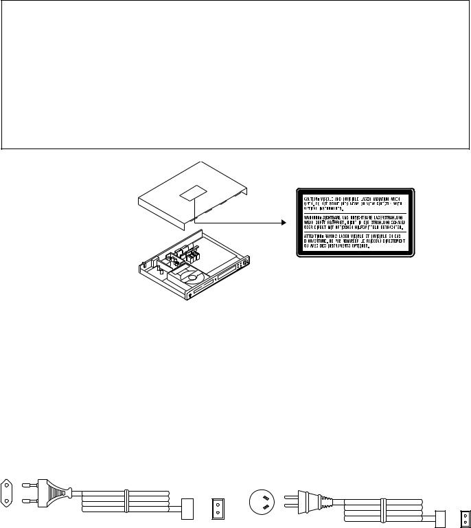
SAFETY PRECAUTION FOR SERVICE MANUAL
WARNINGS
THE AEL (ACCESSIBLE EMISSION LEVEL) OF THE LASER POWER OUTPUT IS LESS THAN CLASS 1 BUT THE LASER COMPONENT IS CAPABLE OF EMITTING RADIATION EXCEEDING THE LIMIT FOR CLASS 1. THEREFORE IT IS IMPORTANT THAT THE FOLLOWING PRECAUTIONS ARE OBSERVED DURING SERVICING TO PROTECT YOUR EYES AGAINST EXPOSURE TO THE LASER BEAM.
1-WHEN THE CABINET IS REMOVED, THE POWER IS TURNED ON WITHOUT A COMPACT DISC IN POSITION AND THE PICKUP IS ON THE OUTER EDGE THE LASER WILL LIGHT FOR SEVERAL SECONDS TO DETECT A DISC. DO NOT LOOK INTO THE PICKUP LENS.
2-THE LASER POWER OUTPUT OF THE PICKUP UNIT AND REPLACEMENT SERVICE PARTS ARE ALL FACTORY PRESET BEFORE SHIPMENT.
DO NOT ATTEMPT TO READJUST THE LASER PICKUP UNIT DURING REPLACEMENT OR SERVICING. 3-UNDER NO CIRCUMSTANCES STARE INTO THE PICKUP LENS AT ANY TIME.
4-CAUTION-USE OF CONTROLS OR ADJUSTMENTS, OR PERFORMANCE OF PROCEDURES OTHER THAN THOSE SPECIFIED HEREIN MAY RESULT IN HAZARDOUS RADIATION EXPOSURE.
Laser Diode Properties
Material: AlGaAs/AlGalnP
Wavelength: 785 nm/650 nm
Emission Duration: continuous
Laser Output: max. 0.6 mW
VOLTAGE SELECTION
After checking all the connections have been made correctly, plug the AC power lead of this unit into the wall socket. Wall socket (AC 220-240 V, 50/60 Hz).
AC POWER SUPPLY CORD
92LVPE16253010
92L2559K022G24
– 2 –
HT-CN400DVW/HT-CN400DVA/HT-CN500DVW/HT-CN500DVA
FOR A COMPLETE DESCRIPTION OF THE OPERATION OF THIS UNIT, PLEASE REFER TO THE OPERATION MANUAL.
SPECIFICATIONS
HT-CN400DVW/HT-CN500DVW
General
|
Power source |
AC 220 - 240 V, 50/60 Hz |
|
|
||
|
|
|
|
|
|
|
|
Power consumption |
HT-CN400DVW: |
|
|
||
|
|
|
Power on: 88 W |
|
|
|
|
|
|
Power stand-by: 0.6 W |
|
|
|
|
|
|
HT-CN500DVW: |
|
|
|
|
|
|
Power on: 105 W |
|
|
|
|
|
|
Power stand-by: 0.6 W |
|
|
|
|
Dimensions |
Width: 430 mm (16-7/8") |
|
|
||
|
|
|
Height: 53 mm (2-1/8") |
|
|
|
|
|
|
Depth: 337 mm (13-1/4") |
|
|
|
|
|
|
|
|
|
|
|
Weight |
4.2 kg (9.3 lbs.) |
|
|
||
|
Audio input terminals |
Analogue input (IN 1): RCA type |
1 pair (L/R) |
|||
|
|
|
Analogue input (IN 2): RCA type |
1 pair (L/R) |
||
|
Audio output |
Analogue output (OUT): RCA type |
1 pair (L/R) |
|||
|
terminals |
|
|
|
|
|
|
Video output |
S-video output: S-terminal 1 |
|
|||
|
terminals |
Video output: RCA type |
1 |
|
||
|
|
|
|
|||
|
|
|
|
|
|
|
|
|
Amplifier (HT-CN400DVW) |
|
|
||
|
|
|
|
|||
|
|
|
|
|||
|
|
|
|
|
|
|
|
Output power |
Front speakers: |
|
|
||
|
|
|
RMS: 60 W (30 W + 30 W) (10 % T.H.D., 1 kHz) |
|||
|
|
|
Centre speaker: |
|
|
|
|
|
|
RMS: 30 W (10 % T.H.D., 1 kHz) |
|
||
|
|
|
Surround speakers: |
|
|
|
|
|
|
RMS: 60 W (30 W + 30 W) (10 % T.H.D., 1 kHz) |
|||
|
|
|
Subwoofer: |
|
|
|
|
|
|
RMS: 50 W (10 % T.H.D., 100 Hz) |
|
||
|
|
Amplifier (HT-CN500DVW) |
|
|
||
|
|
|
|
|||
|
|
|
|
|
|
|
|
Output power |
Front speakers: |
|
|
||
|
|
|
RMS: 100 W (50 W + 50 W) (10 % T.H.D., 1 kHz) |
|||
|
|
|
Centre speaker: |
|
|
|
|
|
|
RMS: 50 W (10 % T.H.D., 1 kHz) |
|
||
|
|
|
Surround speakers: |
|
|
|
|
|
|
RMS: 100 W (50 W + 50 W) (10 % T.H.D., 1 kHz) |
|||
|
|
|
Subwoofer: |
|
|
|
|
|
|
RMS: 50 W (10 % T.H.D., 100 Hz) |
|
||
|
|
DVD player |
|
|
|
|
|
|
|
|
|
|
|
|
|
|
|
|
|
|
|
|
|
|
|
|
|
|
Signal system |
PAL/NTSC colour |
|
|
||
|
Supported disc types |
DVD (with the same region number on the back of the unit |
||||
|
|
|
or ALL), SVCD, VCD, audio CD, CD-R, CD-RW, MP3 |
|||
|
|
|
|
|
||
|
Video signal |
Horizontal resolution: 500 lines |
|
|||
|
|
|
S/N ratio: 70 dB |
|
|
|
|
Audio signal |
Frequency character- |
|
Linear PCM DVD: |
||
|
|
|
istics |
|
20 Hz to 20 kHz |
|
|
|
|
|
|
||
|
|
|
|
|
(sampling rate: 48 kHz) |
|
|
|
|
|
|
20 Hz to 20 kHz |
|
|
|
|
|
|
(sampling rate: 96 kHz) |
|
|
|
|
|
|
CD: 20 Hz to 20 kHz |
|
|
|
|
|
|
|
|
|
|
|
S/N ratio |
|
CD: 94 dB (1 kHz) |
|
|
|
|
|
|
|
|
|
|
|
Dynamic range |
|
Linear PCM DVD: 95 dB |
|
|
|
|
|
|
CD: 94 dB |
|
|
|
|
|
|
|
|
|
|
|
Total harmonic distor- |
|
0.01 % maximum |
|
|
|
|
tion ratio |
|
|
|
|
|
|
|
|
|
|
Tuner
Frequency range |
FM: 88 - 108 MHz |
|
AM: 531 - 1,620 kHz |
CP-CN400WF/CP-CN500WF/CP-CN400WC/CP-CN500WC
Type |
Full range speaker system (magnetic shield) |
|
8 cm (3-1/8") speaker |
|
|
Maximum input power |
HT-CN400DVW: 45 W |
|
|
|
HT-CN500DVW: 60 W |
Impedance |
HT-CN400DVW: 8 ohms |
|
|
|
HT-CN500DVW: 6 ohms |
Dimensions |
Width: 94 mm (3-3/4") |
|
Height: 169 mm (6-5/8") |
|
Depth: 97 mm (3-7/8") |
|
|
Weight |
0.6 kg (1.3 lbs.)/each |
CP-CN400WR/CP-CN500WR
Type |
Full range speaker system |
|
8 cm (3-1/8") speaker |
Maximum input power |
HT-CN400DVW: 45 W |
|
HT-CN500DVW: 60 W |
|
|
Impedance |
HT-CN400DVW: 8 ohms |
|
HT-CN500DVW: 6 ohms |
Dimensions |
Width: 94 mm (3-3/4") |
|
Height: 169 mm (6-5/8") |
|
Depth: 97 mm (3-7/8") |
|
|
Weight |
0.6 kg (1.3 lbs.)/each |
|
|
CP-CN400WSW/CP-CN500WSW
Type |
Sub-woofer system |
|
12 cm (4-3/4") subwoofer |
Maximum input power |
75 W |
|
|
Impedance |
6 ohms |
Dimensions |
Width: 135 mm (5-5/16") |
|
Height: 338 mm (13-5/16") |
|
Depth: 375 mm (14-3/4") |
Weight |
5.3 kg (11.7 lbs.) |
|
|
Specifications for this model are subject to change without prior notice.
– 3 –

HT-CN400DVW/HT-CN400DVA/HT-CN500DVW/HT-CN500DVA
HT-CN400DVA/HT-CN500DVA
General
Power source |
AC 220 - 240 V, 50/60 Hz |
|
||
Power consumption |
HT-CN400DVA: |
|
|
|
|
|
Power on: 88 W |
|
|
|
|
Power stand-by: 0.6 W |
|
|
|
|
HT-CN500DVA: |
|
|
|
|
Power on: 105 W |
|
|
|
|
Power stand-by: 0.6 W |
|
|
|
|
|
|
|
Dimensions |
Width: 430 mm (16-7/8") |
|
|
|
|
|
Height: 53 mm (2-1/8") |
|
|
|
|
Depth: 337 mm (13-1/4") |
|
|
Weight |
4.2 kg (9.3 lbs.) |
|
|
|
Audio input terminals |
Analogue input (IN 1): RCA type |
1 pair (L/R) |
||
|
|
Analogue input (IN 2): RCA type |
1 pair (L/R) |
|
|
|
|
|
|
Audio output |
Analogue output (OUT): RCA type |
1 pair (L/R) |
||
terminals |
Headphones: 16 - 50 ohms (recommended: 32 ohms) |
|||
|
|
|||
Video output |
S-video output: S-terminal 1 |
|
||
terminals |
Video output: RCA type |
1 |
|
|
|
|
|
||
|
Amplifier (HT-CN400DVA) |
|
|
|
|
|
|
||
|
|
|
|
|
Output power |
Front speakers: |
|
|
|
|
|
RMS: 60 W (30 W + 30 W) (10 % T.H.D., 1 kHz) |
||
|
|
Centre speaker: |
|
|
|
|
RMS: 30 W (10 % T.H.D., 1 kHz) |
|
|
|
|
Surround speakers: |
|
|
|
|
RMS: 60 W (30 W + 30 W) (10 % T.H.D., 1 kHz) |
||
|
|
Subwoofer: |
|
|
|
|
RMS: 50 W (10 % T.H.D., 100 Hz) |
|
|
|
Amplifier (HT-CN500DVA) |
|
|
|
|
|
|
||
|
|
|
||
|
|
|
|
|
Output power |
Front speakers: |
|
|
|
|
|
RMS: 100 W (50 W + 50 W) (10 % T.H.D., 1 kHz) |
||
|
|
Centre speaker: |
|
|
|
|
RMS: 50 W (10 % T.H.D., 1 kHz) |
|
|
|
|
Surround speakers: |
|
|
|
|
RMS: 100 W (50 W + 50 W) (10 % T.H.D., 1 kHz) |
||
|
|
Subwoofer: |
|
|
|
|
RMS: 50 W (10 % T.H.D., 100 Hz) |
|
|
|
DVD player |
|
|
|
|
|
|
|
|
|
|
|
|
|
|
|
|
|
|
Signal system |
PAL/NTSC colour |
|
|
|
Supported disc types |
DVD (Region number 4, ALL), SVCD, VCD, audio CD, |
|||
|
|
CD-R, CD-RW, MP3 |
|
|
|
|
|
|
|
Video signal |
Horizontal resolution: 500 lines |
|
||
|
|
S/N ratio: 70 dB |
|
|
Audio signal |
Frequency character- |
Linear PCM DVD: |
||
|
|
istics |
20 Hz to 20 kHz |
|
|
|
|
||
|
|
|
(sampling rate: 48 kHz) |
|
|
|
|
20 Hz to 20 kHz |
|
|
|
|
(sampling rate: 96 kHz) |
|
|
|
|
CD: 20 Hz to 20 kHz |
|
|
|
|
|
|
|
|
S/N ratio |
CD: 94 dB (1 kHz) |
|
|
|
|
|
|
|
|
Dynamic range |
Linear PCM DVD: 95 dB |
|
|
|
|
CD: 94 dB |
|
|
|
|
|
|
|
|
Total harmonic distor- |
0.01 % maximum |
|
|
|
tion ratio |
|
|
|
|
|
|
|
Tuner
Frequency range |
FM: 87.5 - 108 MHz |
|
AM: 522 - 1,620 kHz |
|
|
CP-CN400F/CP-CN500F/CP-CN400C/CP-CN500C
Type |
Full range speaker system (magnetic shield) |
|
8 cm (3-1/8") speaker |
|
|
Maximum input power |
HT-CN400DVA: 45 W |
|
HT-CN500DVA: 60 W |
|
|
Impedance |
HT-CN400DVA: 8 ohms |
|
|
|
HT-CN500DVA: 6 ohms |
Dimensions |
Width: 94 mm (3-3/4") |
|
Height: 169 mm (6-5/8") |
|
Depth: 97 mm (3-7/8") |
Weight |
0.6 kg (1.3 lbs.)/each |
CP-CN400R/CP-CN500R
Type |
Full range speaker system |
|
8 cm (3-1/8") speaker |
|
|
Maximum input power |
HT-CN400DVA: 45 W |
|
HT-CN500DVA: 60 W |
Impedance |
HT-CN400DVA: 8 ohms |
|
|
|
HT-CN500DVA: 6 ohms |
|
|
Dimensions |
Width: 94 mm (3-3/4") |
|
Height: 169 mm (6-5/8") |
|
Depth: 97 mm (3-7/8") |
|
|
Weight |
0.6 kg (1.3 lbs.)/each |
CP-CN400SW/CP-CN500SW
Type |
Sub-woofer system |
|
12 cm (4-3/4") subwoofer |
|
|
Maximum input power |
75 W |
|
|
Impedance |
6 ohms |
|
|
Dimensions |
Width: 135 mm (5-5/16") |
|
Height: 338 mm (13-5/16") |
|
Depth: 375 mm (14-3/4") |
Weight |
5.3 kg (11.7 lbs.) |
|
|
Specifications for this model are subject to change without prior notice.
– 4 –
HT-CN400DVW/HT-CN400DVA/HT-CN500DVW/HT-CN500DVA
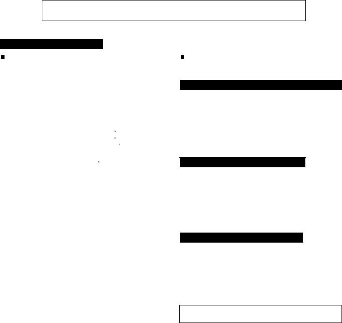
NAMES OF PARTS
HT-CN400DVW/HT-CN500DVW
 Main unit (front panel)
1 |
|
|
|
|
|
|
|
|
2 |
|
|
|
|
3 |
|
4 |
|
|
|
|
|
|
|
|
5 |
|
6 |
|
|
|
|
|
7 |
|
|
|
|
|
|
|
13 |
|
|
|
|||
|
|
|
|
|
|
|
|
|
|
|
|
|
|
|
|
|
|
|
|
|
|
|
|
|
|
|
|
|
|
|
|
|
|
|
|
|
|
|
|
|
|
|
|
|
|
|
|
|
|
|
|
|
|
|
|
|
|
|
|
|
|
|
|
|
|
|
|
|
|
|
|
|
|
|
|
|
|
|
|
|
|
|
|
|
|
|
|
|
|
|
|
14 |
|||
|
|
|
|
|
|
|
|
|
|
|
|
|
|
|
|
|
|
|
|
|
|
|
|
|
|
|
|
|
|
|
|
|
|
|
|
|
|
|
12 |
|
|
|
|
||||
|
|
|
|
|
|
|
|
|
|
|
|
|
|
|
|
|
|
|
|
|
|
|
|
|
|
|
|
|
|
|
|
|
|
|
|
|
|
|
|
|
|
|
13 |
||||
|
|
|
|
|
|
|
|
|
|
|
|
|
|
|
|
|
|
|
|
|
|
|
|
|
|
|
|
|
|
|
|
|
|
|
|
|
|
|
|
||||||||
|
|
|
8 |
|
|
|
|
|
|
|
|
|
|
|
|
|
|
|
|
|
|
|
|
|
|
|
|
9 |
|
|
10 |
11 |
|
|
|
||||||||||||
|
|
|
|
|
(1) (2) (3) |
16 |
17 |
18 |
19 |
|
|
20 |
21 |
22 |
|
23 |
24 |
25 |
26 |
|
|
|
|
|
27 |
28 |
|
|
|
|
|
|
|
|
|
|
|
||||||||||
|
|
|
|
|
|
|
|
|
|
|
|
|
|
|
|
|
|
|
|
|
|
|
|
|
|
|
|
|
|
|
|
|
|
|
|
|
|
|
|
|
|
|
|
|
|
|
|
|
|
|
15 |
L |
|
|
R |
|
|
L |
C |
R |
|
|
|
|
|
TITLE |
TRK |
PRESET |
CHP |
PROG |
SLEEP |
|
|
|
|
|
|
REPEAT 1 |
A - B |
|
|
|
|
|
|
|
|
|
|
|
|||||
|
|
|
C |
|
|
|
|
|
|
|
|
|
|
|
|
|
KHz |
|
|
|
|
|
|
|
|
|
|
||||||||||||||||||||
|
|
|
|
|
|
|
|
|
|
|
|
|
|
|
|
DIGITAL |
|
|
|
|
|
|
|
|
|
|
|
|
|
|
|
|
|
|
|
|
|
|
|
|
|
|
|
|
|
||
|
|
|
|
|
|
|
|
|
|
|
|
|
|
|
|
Pro Logic |
|
|
|
|
|
|
|
|
|
|
|
|
|
|
|
|
|
|
|
|
|
|
|
|
|
|
|
|
|
||
|
|
|
|
|
LS |
S |
RS |
|
|
LS |
S |
|
|
|
|
|
|
|
|
|
|
|
|
|
|
|
|
|
|
|
MHz |
|
|
|
|
|
|
|
|
|
|
||||||
|
|
|
|
|
|
|
RS |
STEREO VCD MP3 |
|
|
|
|
|
|
|
|
|
|
|
|
|
|
|
|
|
|
|
|
|
|
|
|
|||||||||||||||
|
|
|
|
|
|
|
|
|
|
|
|
|
|
|
|
|
|
|
|
|
|
|
|
|
|
|
|
|
|
|
|
|
|
|
|
|
|
|
|
|
|
|
|
|
|
||
|
|
|
|
|
|
|
|
|
|
|
|
|
|
|
|
|
|
|
|
|
|
|
|
|
|
|
|
|
|
|
|
|
|
|
|
|
|
|
|
|
|
|
|
|
|
||
|
|
|
|
|
(4) (5) (6) |
|
|
|
|
|
29 |
30 |
31 |
|
32 |
|
|
|
|
|
|
|
|
|
|
|
|
|
|
|
|
|
|
|
|
|
|
|
|
|
|||||||
1. |
On/Stand-by Button |
|
|
|
|
|
|
|
|
|
|
|
|
|
|
|
|
|
|
|
16. |
Dolby Pro Logic Indicator |
|
|
|
|
|
|
|
|
|
|
|
|
|||||||||||||
2. |
Disc Tray |
|
|
|
|
|
|
|
|
|
|
|
|
|
|
|
|
|
|
|
17. |
Dolby Digital Signal Indicator |
|
|
|
|
|
|
|
|
|
|
|
||||||||||||||
3. |
Disc Tray Open/Close Button |
|
|
|
|
|
|
|
|
|
|
|
|
|
|
|
18. |
DVD Indicator |
|
|
|
|
|
|
|
|
|
|
|
|
|
|
|
|
|
|
|
||||||||||
4. |
Remote Sensor |
|
|
|
|
|
|
|
|
|
|
|
|
|
|
|
|
|
|
|
19. |
Pause Indicator |
|
|
|
|
|
|
|
|
|
|
|
|
|
||||||||||||
5. |
Function Button |
|
|
|
|
|
|
|
|
|
|
|
|
|
|
|
|
|
|
|
20. |
Play Indicator |
|
|
|
|
|
|
|
|
|
|
|
|
|
|
|
|
|
|
|
||||||
6. |
Play or Pause Button |
|
|
|
|
|
|
|
|
|
|
|
|
|
|
|
|
|
|
|
21. |
Title Indicator |
|
|
|
|
|
|
|
|
|
|
|
|
|
|
|
|
|
|
|
||||||
7. |
Stop Button |
|
|
|
|
|
|
|
|
|
|
|
|
|
|
|
|
|
|
|
22. |
Track Indicator |
|
|
|
|
|
|
|
|
|
|
|
|
|
|
|
|
|
|
|
||||||
8. |
Power Stand-by Indicator |
|
|
|
|
|
|
|
|
|
|
|
|
|
|
|
|
|
23. |
Tuner Preset Indicator |
|
|
|
|
|
|
|
|
|
|
|
|
|
||||||||||||||
9. |
Microphone Volume Control |
|
|
|
|
|
|
|
|
|
|
|
|
|
|
|
24. |
Chapter Indicator |
|
|
|
|
|
|
|
|
|
|
|
|
|
||||||||||||||||
10. |
Speaker Level Mode Button |
|
|
|
|
|
|
|
|
|
|
|
|
|
|
|
25. |
Programme Indicator |
|
|
|
|
|
|
|
|
|
|
|
|
|
||||||||||||||||
11. |
Microphone Socket |
|
|
|
|
|
|
|
|
|
|
|
|
|
|
|
|
|
|
|
26. |
Sleep Indicator |
|
|
|
|
|
|
|
|
|
|
|
|
|
||||||||||||
12. |
Chapter (track) Skip Down or Tuning Down Button |
|
|
|
|
|
|
|
27. |
Repeat Indicator |
|
|
|
|
|
|
|
|
|
|
|
|
|
||||||||||||||||||||||||
13. |
Volume Up and Down or Speaker Level Adjust Buttons |
|
|
|
|
|
|
28. |
A - B Repeat Indicator |
|
|
|
|
|
|
|
|
|
|
|
|
|
|||||||||||||||||||||||||
14. |
Chapter (track) Skip Up or Tuning Up Button |
|
|
|
|
|
|
|
|
|
29. |
DTS Signal Indicator |
|
|
|
|
|
|
|
|
|
|
|
|
|
||||||||||||||||||||||
15. |
Speaker Indicators |
|
|
|
|
|
|
|
|
|
|
|
|
|
|
|
|
|
|
|
30. |
Stereo (2-ch) or FM Stereo Receiving Indicator |
|
|
|
|
|||||||||||||||||||||
|
|
|
(1) Left Front Speaker Indicator |
|
|
|
|
(4) Left Surround Speaker Indicator |
|
31. SVCD/VCD/CD Indicator |
|
|
|
|
|
|
|
|
|
|
|
|
|||||||||||||||||||||||||
|
|
|
(2) Centre Speaker Indicator |
|
|
|
|
(5) Subwoofer Indicator |
|
|
|
|
|
|
32. |
MP3 or JPEG Indicator |
|
|
|
|
|
|
|
|
|
|
|
|
|||||||||||||||||||
|
|
|
(3) Right Front Speaker Indicator |
|
|
|
|
(6) Right Surround Speaker Indicator |
|
|
|
|
|
|
|
|
|
|
|
|
|
|
|
|
|
|
|
|
|
|
|
|
|
||||||||||||||
|
|
|
|
|
|
|
|
|
|
|
|
|
|
|
|
|
|
|
|
|
|
|
|
|
|
|
|
|
|
|
|
|
|
|
|
||||||||||||
|
|
|
|
HT-CN400DVA/HT-CN500DVA |
|
|
|
|
|
|
|
|
|
|
|
|
|
|
|
|
|
|
|
|
|
|
|
|
|
|
|
|
|
|
|
||||||||||||
|
|
|
Main unit (front panel) |
|
|
|
|
|
|
|
|
|
|
|
|
|
|
|
|
|
|
|
|
|
|
|
|
|
|
|
|
|
|
|
|
|
|||||||||||
|
|
|
|
|
|
|
|
|
|
|
|
|
|
|
|
|
|
|
|
|
|
|
|
|
|
|
|
|
|
|
|
|
|
|
|
||||||||||||
1 |
|
|
|
|
|
|
|
|
2 |
|
|
|
|
3 |
|
4 |
|
|
|
|
|
|
|
|
|
|
5 |
|
|
|
|
|
6 |
|
|
|
|
|
|
|
12 |
|
|
|
|||
|
|
|
|
|
|
|
|
|
|
|
|
|
|
|
|
|
|
|
|
|
|
|
|
|
|
|
|
|
|
|
|
|
|
|
|
|
|
|
|
|
|
|
|
|
|
|
|
|
|
|
|
|
|
|
|
|
|
|
|
|
|
|
|
|
|
|
|
|
|
|
|
|
|
|
|
|
|
|
|
|
|
|
|
|
|
|
|
|
|
|
|
13 |
|||
|
|
|
|
|
|
|
|
|
|
|
|
|
|
|
|
|
|
|
|
|
|
|
|
|
|
|
|
|
|
|
|
|
|
|
|
|
|
11 |
|
|
|
|
|||||
|
|
|
|
|
|
|
|
|
|
|
|
|
|
|
|
|
|
|
|
|
|
|
|
|
|
|
|
|
|
|
|
|
|
|
|
|
|
|
|
|
|
12 |
|||||
|
|
|
|
|
|
|
|
|
|
|
|
|
|
|
|
|
|
|
|
|
|
|
|
|
|
|
|
|
|
|
|
|
|
|
|
|
|
|
|||||||||
|
|
|
7 |
|
|
|
|
|
|
|
|
|
|
|
|
|
|
|
|
|
|
|
|
|
|
|
|
8 |
|
|
|
|
|
9 |
10 |
|
|
||||||||||
|
|
|
|
|
(1) (2) (3) |
15 |
16 |
17 |
18 |
|
|
19 |
20 |
21 |
|
22 |
23 |
24 |
25 |
|
|
|
|
|
26 |
27 |
|
|
|
|
|
|
|
|
|
|
|
||||||||||
|
|
|
|
|
|
|
|
|
|
|
|
|
|
|
|
|
|
|
|
|
|
|
|
|
|
|
|
|
|
|
|
|
|
|
|
|
|
|
|
|
|
|
|
|
|
|
|
|
|
|
14 |
L |
|
|
R |
|
|
L |
C |
R |
|
|
|
|
|
TITLE |
TRK |
PRESET CHP |
PROG |
SLEEP |
|
|
|
|
|
|
REPEAT 1 |
A - B |
|
|
|
|
|
|
|
|
|
|
|
||||||
|
|
|
C |
|
|
|
|
|
|
|
|
|
|
|
|
|
KHz |
|
|
|
|
|
|
|
|
|
|
||||||||||||||||||||
|
|
|
|
|
|
|
|
|
|
|
|
|
|
|
|
DIGITAL |
|
|
|
|
|
|
|
|
|
|
|
|
|
|
|
|
|
|
|
|
|
|
|
|
|
|
|
|
|
||
|
|
|
|
|
|
|
|
|
|
|
|
|
|
|
|
Pro Logic |
|
|
|
|
|
|
|
|
|
|
|
|
|
|
|
|
|
|
|
|
|
|
|
|
|
|
|
|
|
||
|
|
|
|
|
LS |
S |
RS |
|
|
LS |
S |
RS |
STEREO VCD MP3 |
|
|
|
|
|
|
|
|
|
|
|
|
|
|
MHz |
|
|
|
|
|
|
|
|
|||||||||||
|
|
|
|
|
|
|
|
|
|
|
|
|
|
|
|
|
|
|
|
|
|
|
|
|
|
|
|
|
|
|
|
|
|
|
|
|
|
|
|
|
|
|
|
|
|
||
|
|
|
|
|
|
|
|
|
|
|
|
|
|
|
|
|
|
|
|
|
|
|
|
|
|
|
|
|
|
|
|
|
|
|
|
|
|
|
|
|
|
|
|
||||
|
|
|
|
|
(4) (5) (6) |
|
|
|
|
|
28 |
29 |
30 |
|
31 |
|
|
|
|
|
|
|
|
|
|
|
|
|
|
|
|
|
|
|
|
|
|
|
|
|
|||||||
|
1. On/Stand-by Button |
|
|
|
|
|
|
|
|
|
|
|
|
|
|
|
|
|
|
|
15. |
Dolby Pro Logic Indicator |
|
|
|
|
|
|
|
|
|
|
|
|
|||||||||||||
|
2. Disc Tray |
|
|
|
|
|
|
|
|
|
|
|
|
|
|
|
|
|
|
|
16. |
Dolby Digital Signal Indicator |
|
|
|
|
|
|
|
|
|
|
|
||||||||||||||
|
3. VDisc Tray Open/Close Button |
|
|
|
|
|
|
|
|
|
|
|
|
|
|
|
17. |
DVD Indicator |
|
|
|
|
|
|
|
|
|
|
|
|
|
|
|
|
|
|
|
||||||||||
|
4. Remote Sensor |
|
|
|
|
|
|
|
|
|
|
|
|
|
|
|
|
|
|
|
18. |
Pause Indicator |
|
|
|
|
|
|
|
|
|
|
|
|
|
||||||||||||
|
5. Play or Pause Button |
|
|
|
|
|
|
|
|
|
|
|
|
|
|
|
|
|
|
|
19. |
Play Indicator |
|
|
|
|
|
|
|
|
|
|
|
|
|
|
|
|
|
|
|
||||||
|
6. Stop Button |
|
|
|
|
|
|
|
|
|
|
|
|
|
|
|
|
|
|
|
20. |
Title Indicator |
|
|
|
|
|
|
|
|
|
|
|
|
|
|
|
|
|
|
|
||||||
|
7. Power Stand-by Indicator |
|
|
|
|
|
|
|
|
|
|
|
|
|
|
|
|
|
21. |
Track Indicator |
|
|
|
|
|
|
|
|
|
|
|
|
|
||||||||||||||
|
8. Function Button |
|
|
|
|
|
|
|
|
|
|
|
|
|
|
|
|
|
|
|
22. |
Tuner Preset Indicator |
|
|
|
|
|
|
|
|
|
|
|
|
|
||||||||||||
|
9. Speaker Level Mode Button |
|
|
|
|
|
|
|
|
|
|
|
|
|
|
|
23. |
Chapter Indicator |
|
|
|
|
|
|
|
|
|
|
|
|
|
||||||||||||||||
10. Headphone Socket |
|
|
|
|
|
|
|
|
|
|
|
|
|
|
|
|
|
|
|
24. |
Programme Indicator |
|
|
|
|
|
|
|
|
|
|
|
|
|
|||||||||||||
11. Chapter (track) Skip Down or Tuning Down Button |
|
|
|
|
|
|
|
25. |
Sleep Indicator |
|
|
|
|
|
|
|
|
|
|
|
|
|
|||||||||||||||||||||||||
12. Volume Up and Down or Speaker Level Adjust Buttons |
|
|
|
|
|
|
26. |
Repeat Indicator |
|
|
|
|
|
|
|
|
|
|
|
|
|
||||||||||||||||||||||||||
13. Chapter (track) Skip Up or Tuning Up Button |
|
|
|
|
|
|
|
|
|
27. |
A - B Repeat Indicator |
|
|
|
|
|
|
|
|
|
|
|
|
|
|||||||||||||||||||||||
14. Speaker Indicators |
|
|
|
|
|
|
|
|
|
|
|
|
|
|
|
|
|
|
|
28. |
DTS Signal Indicator |
|
|
|
|
|
|
|
|
|
|
|
|
|
|||||||||||||
|
|
|
|
(1) Left Front Speaker Indicator |
|
|
|
|
(4) Left Surround Speaker Indicator |
|
29. |
Stereo (2-ch) or FM Stereo Receiving Indicator |
|
|
|
|
|||||||||||||||||||||||||||||||
|
|
|
|
(2) Centre Speaker Indicator |
|
|
|
|
(5) Subwoofer Indicator |
|
|
|
|
|
|
30. SVCD/VCD/CD Indicator |
|
|
|
|
|
|
|
|
|
|
|
|
|||||||||||||||||||
|
|
|
|
(3) Right Front Speaker Indicator |
|
|
(6) Right Surround Speaker Indicator |
|
31. |
MP3 or JPEG Indicator |
|
|
|
|
|
|
|
|
|
|
|
|
|||||||||||||||||||||||||
– 5 –
HT-CN400DVW/HT-CN400DVA/HT-CN500DVW/HT-CN500DVA
HT-CN400DVW/HT-CN400DVA/HT-CN500DVW/HT-CN500DVA
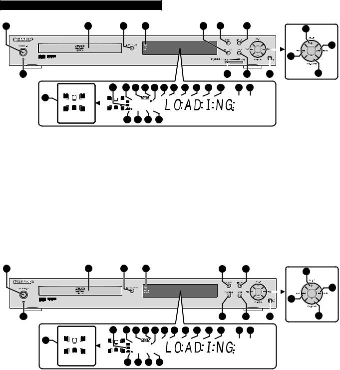
 Main unit (rear panel)
1 |
2 |
3 |
4 |
5 |
6 |
7 |
8 |
|||||||||
|
|
|
|
|
|
|
|
|
|
|
|
|
|
|
|
|
|
|
|
|
|
|
|
|
|
|
|
|
|
|
|
|
|
|
|
|
|
|
|
|
|
|
|
|
|
|
|
|
|
|
|
|
|
|
|
|
|
|
|
|
|
|
|
|
|
|
|
|
|
|
|
|
|
|
|
|
|
|
|
|
|
|
|
|
|
|
|
|
|
|
|
|
|
|
|
|
|
|
|
|
|
|
|
|
|
|
|
|
|
|
|
|
|
|
|
|
|
|
|
|
|
|
|
|
|
|
|
|
|
|
|
|
|
|
|
9
1.FM 75 Ohms Aerial Socket
2.AM Loop Aerial Socket
3.Audio Input Sockets 1/2
4.Audio Output Sockets
5.Video Output Socket
6.Speaker Terminals
7.Cooling Fan
8.AC Power Lead
9.S-video Output Socket
HT-CN400DVW/HT-CN500DVW
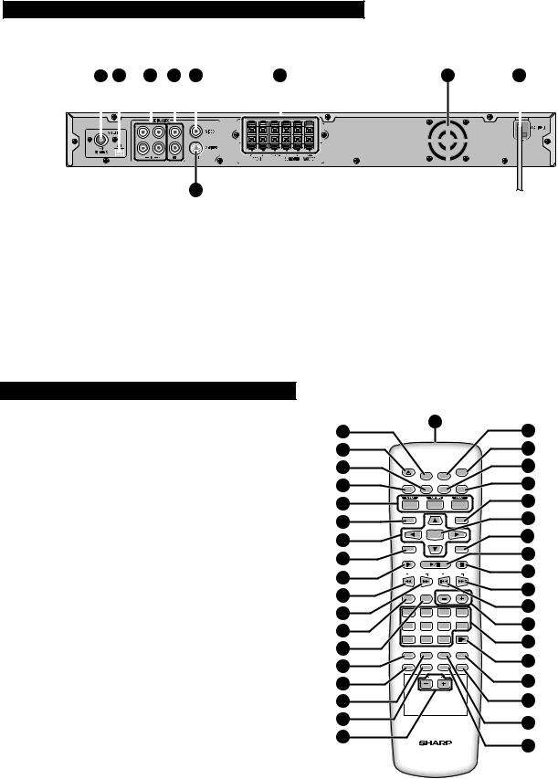
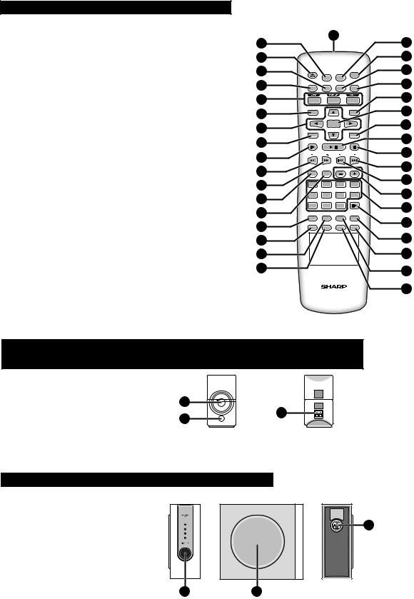
 Remote control
1.Remote Control Transmitter
2.Set Up Menu Button
3.Disc Tray Open/Close Button
4.Subtitle Select Button
5.Title Select Button
6.DVD/Tuner/Auxiliary Input Select Buttons
7.Menu/Playback Control On/Off Button
8.Cursor Buttons
9.Programme Button
10.Slow-motion or Preset Memory Button
11.Fast Reverse or Preset Down Button
12.Fast Forward or Preset Up Button
13.Surround/Stereo (2-ch) Listening Mode Button
14.Speaker Level Mode Button
15.Direct Button
16.Angle Select Button
17.Return Button
18.Zoom Button
19.Echo Level Up and Down Buttons
20.Mute Button
21.On/Stand-by Button
22.Language Select Button
23.Display Button
24.FM Stereo/Mono Select Button
25.Enter Button
26.Sleep Button
27.Play or Pause Button
28.Stop Button
29.Chapter (track) Skip Up or Tuning Up Button
30.Chapter (track) Skip Down or Tuning Down Button
31.Volume Up and Down or Speaker Level Adjust Buttons
32.Direct Number Buttons
33.Frame Advance Button
34.A - B Repeat Button
35.NTSC/PAL Select Button
36.Repeat Play Button
37.Audio Select Button
2 |
|
1 |
|
20 |
||
|
|
|
|
|||
3 |
|
|
|
|
21 |
|
4 |
OPEN/ |
|
|
ON/ |
22 |
|
CLOSE |
SET UP |
MUTE |
STAND-BY |
|||
|
|
|||||
5 |
TITLE |
SUBTITLE LANGUAGE DISPLAY |
23 |
|||
6 |
|
|
|
|
24 |
|
7 |
MENU/PBC |
|
ST/MO |
25 |
||
|
|
|
|
|||
|
|
|
|
26 |
||
8 |
|
ENTER |
|
|||
PROG |
|
|
SLEEP |
|
||
9 |
SLOW/MEMORY |
|
|
27 |
||
|
|
|
||||
10 |
PRESET |
TUNING |
28 |
|||
|
|
|
|
29 |
||
11 |
LISTENING MODE |
ADJ/VOL |
||||
|
|
|
|
30 |
||
12 |
1 |
2 |
3 |
4 |
||
|
||||||
13 |
5 |
6 |
7 |
8 |
31 |
|
|
|
|
STEP |
|
||
14 |
9 |
0 |
>10 |
|
32 |
|
DIRECT RETURN REPEAT |
A-B |
|||||
33 |
||||||
15 |
ANGLE |
ZOOM |
AUDIO NTSC/PAL |
|||
|
|
|
MULTI |
|
||
|
|
ECHO |
34 |
|||
16 |
|
|
||||
|
|
|
|
|||
17 |
|
|
|
|
35 |
|
18 |
|
|
|
|
36 |
|
|
|
|
|
|
||
19
37
– 6 –
HT-CN400DVW/HT-CN400DVA/HT-CN500DVW/HT-CN500DVA
HT-CN400DVA/HT-CN500DVA
 Remote control
1.Remote Control Transmitter
2.Set Up Menu Button
3.Disc Tray Open/Close Button
4.Subtitle Select Button
5.Title Select Button
6.DVD/Tuner/Auxiliary Input Select Buttons
7.Menu/Playback Control On/Off Button
8.Cursor Buttons
9.Programme Button
10.Slow-motion or Preset Memory Button
11.Fast Reverse or Preset Down Button
12.Fast Forward or Preset Up Button
13.Surround/Stereo (2-ch) Listening Mode Button
14.Speaker Level Mode Button
15.Direct Button
16.Angle Select Button
17.Return Button
18.Zoom Button
19.Mute Button
20.On/Stand-by Button
21.Language Select Button
22.Display Button
23.FM Stereo/Mono Select Button
24.Enter Button
25.Sleep Button
26.Play or Pause Button
27.Stop Button
28.Chapter (track) Skip Up or Tuning Up Button
29.Chapter (track) Skip Down or Tuning Down Button
30.Volume Up and Down or Speaker Level Adjust Buttons
31.Direct Number Buttons
32.Frame Advance Button
33.A - B Repeat Button
34.NTSC/PAL Select Button
35.Repeat Play Button
36.Audio Select Button
2 |
|
1 |
|
19 |
||
|
|
|
|
|||
3 |
|
|
|
|
20 |
|
4 |
OPEN/ |
|
|
ON/ |
21 |
|
CLOSE |
SET UP |
MUTE |
STAND-BY |
|||
|
|
|||||
5 |
TITLE |
SUBTITLE LANGUAGE DISPLAY |
22 |
|||
6 |
|
|
|
|
23 |
|
7 |
MENU/PBC |
|
ST/MO |
24 |
||
|
|
|
|
|||
|
|
|
|
25 |
||
8 |
|
ENTER |
|
|||
PROG |
|
|
SLEEP |
|
||
9 |
SLOW/MEMORY |
|
|
26 |
||
|
|
|
||||
10 |
PRESET |
TUNING |
27 |
|||
|
|
|
|
28 |
||
11 |
LISTENING MODE |
ADJ/VOL |
||||
|
|
|
|
29 |
||
12 |
1 |
2 |
3 |
4 |
||
|
||||||
13 |
5 |
6 |
7 |
8 |
30 |
|
|
|
|
STEP |
|
||
14 |
9 |
0 |
>10 |
|
31 |
|
DIRECT RETURN REPEAT |
A-B |
|||||
32 |
||||||
15 |
ANGLE |
ZOOM |
AUDIO |
NTSC/PAL |
||
|
|
|
|
|
||
16 |
|
|
|
|
33 |
|
17 |
|
|
|
|
34 |
|
18 |
|
|
|
|
35 |
|
|
|
|
|
|
||
|
|
|
|
|
36 |
|
CP-CN400WF/CP-CN400WC/CP-CN400WR/CP-CN400F/CP-CN400C/CP-CN400R/ CP-CN500WF/CP-CN500WC/CP-CN500WR/CP-CN500F/CP-CN500C/CP-CN500R
1. Speaker
2. Bass Reflex Duct
3. Speaker Terminals
1
3
2
CP-CN400WSW/CP-CN400SW/CP-CN500WSW/CP-CN500SW
1. Bass Reflex Duct |
3 |
2. Woofer |
|
3. Speaker Terminals |
|
1 |
2 |
– 7 –

HT-CN400DVW/HT-CN400DVA/HT-CN500DVW/HT-CN500DVA
DISASSEMBLY
(B2)x1
Caution on Disassembly
Follow the below-mentioned notes when disassembling the unit and reassembling it, to keep it safe and ensure excellent performance:
1.Take dvd disc out of the unit.
2.Be sure to remove the power supply plug from the wall outlet before starting to disassemble the unit.
3.Take off nylon bands or wire holders where they need to be removed when disassembling the unit. After servicing the unit, be sure to rearrange the leads where they were before disassembling.
4.Take sufficient care on static electricity of integrated circuits and other circuits when servicing.
|
Front |
Main PWB |
Panel |
|
Lug Wire
(B1)x7 |
ø3x8mm |
Fan Motor
HT-CN400DVW/HT-CN400DVA/HT-CN500DVW/HT-CN500DVA
STEP |
REMOVAL |
|
PROCEDURE |
FIGURE |
|
|
|
|
|
|
|
1 |
Top Cabinet |
1. |
Screw ...................... |
(A1) x7 |
8-1 |
|
|
2. |
Pull to the arrow direction. |
|
|
|
|
|
|
|
|
2 |
Rear Panel with |
1. Screw .................... |
(B1) x11 |
8-2 |
|
|
Fan Motor |
2. |
Socket ..................... |
(B2) x1 |
|
|
|
|
|
|
|
3 |
Main PWB |
1. |
Screw ...................... |
(C1) x5 |
8-3 |
|
|
2. |
PWB Shield Cover .. |
(C2) x1 |
|
|
|
3. |
Socket ..................... |
(C3) x6 |
8-4 |
|
|
4. |
Socket ..................... |
(C4) x1 |
|
|
|
|
(HT-CN400DVW/ |
|
|
|
|
HT-CN500DVW Only) |
|
|
|
|
|
5. |
Flat Cable ............... |
(C5) x2 |
|
|
|
6. |
PWB Holder ........... |
(C6) x1 |
8-3 |
|
|
|
|
|
|
4 |
Power PWB |
1. |
Screw ...................... |
(D1) x4 |
8-3 |
|
|
4. |
PWB Holder ........... |
(D1) x2 |
8-4 |
|
|
|
|
|
|
5 |
Front Panel |
1. |
Screw ...................... |
(E1) x8 |
9-1 |
|
|
2. |
Hook ........................ |
(E2) x3 |
|
|
|
|
|
|
|
6 |
Display/Switch |
1. Screw ....................... |
(F1) x9 |
9-2 |
|
|
PWB |
|
|
|
|
|
|
|
|
|
|
7 |
Earphones |
1. |
Screw ...................... |
(G1) x1 |
9-2 |
|
PWB |
2. |
Bracket .................... |
(G2) x1 |
|
|
|
|
|
|
|
HT-CN400DVW/HT-CN400DVA/HT-CN500DVW/HT-CN500DVA
(A1)x1
ø3x6mm
Front
Panel
Pull
(A1)x1
ø3x6mm
Pull
Rear Panel
(B1)x4 Rear Panel ø3x6mm
Figure 8-2
(C1)x5
ø3x8mm
Washer
(C2)x1
Loading Tray
Mechanism
Front
Panel
Main PWB |
(C6)x4 |
(D1)x4 |
|
Push |
Push |
|
|
|
ø3x8mm |
|
|
Power PWB |
Figure 8-3
(C3)x2 |
|
|
(C4)x1 |
(C5)x1 |
|
(HT-CN400DVW/ |
||
|
||
HT-CN500DVW |
(C3)x2 |
|
Only) |
|
(C3)x2 |
(C5)x1 |
|
|
Main PWB |
|
Front
Panel
(A1)x5 |
Top Cabinet |
ø3x6mm |
(D2)x2 |
|
Push Push |
Loading |
|
Tray Mechanism |
|
Power PWB |
Figure 8-1
Figure 8-4
– 8 –
 Loading...