


Sharp GP1F32R, GP1F31T, GP1F31R, GP1C335, GP1C331A Datasheet
...GP1F31T/R, GP1F32T/R, GP1F33TT/RR/RT, GP1C331/331A/335
GP1F31T/R, GP1F32T/R, GP1F33TT/RR/RT, GP1C331/331A/335
Light Transmitting
/Receiving Units
■ Features
1. Low jitter ( tj : TYP. 1ns)
2.High speed signal transmission ( 8Mbps, NRZ signal )
3.Directly connectable to modulation /demoduration IC for digital audio equipment
•Light transmitting unit••• Built-in light emitting diode driving circuit
•Light receiving unit••• Built-in signal processing circuit
4.With two fixing holes for easy mounting on set panel
(GP1F32T/GP1F32R/GP1F33RR/GP1F33TT/33RT )
5. 2-channel type
(GP1F33RR/GP1F33TT/GP1F33RT)
We recommend you to use Sharp's optical fiber cable, (GP1C331,GP1C331A , GP1C335)
■ Applications
1.CD players
2.BS tuners
3.Digital amplifiers
■ Model Line-ups
Model No. |
Internal Constitution |
GP1F31T |
Light transmitting unit |
GP1F31R |
Light receiving unit |
GP1F32T |
Light transmitting unit |
GP1F32R |
Light receiving unit |
GP1F33TT |
Dual light transmitting unit |
GP1F33RR |
Dual light receiving unit |
GP1F33RT |
Light transmitting & receiving units |
GP1C331 |
Optical fiber cable ( 1m ) |
GP1C331A |
Optical fiber cable ( 0.6m ) |
GP1C335 |
Optical fiber cable ( 5m ) |
■ Outline Dimensions |
|
|
|
|
|
|
|
|
|
|
|
|
|
|
(Unit : mm ) |
||||||||
GP1F31T/GP1F31R |
|
|
|
|
|
|
|
|
GP1F32T/GP1F32R |
|
|
|
|
|
|
Protection cap |
|
|
|||||
|
|
|
|
|
|
|
|
|
|
φ 2.5 fixing hole φ 4 |
|
|
|
|
|
|
|
|
|||||
|
|
|
|
|
|
|
|
|
|
|
|
|
|
|
|
2 |
3.7 |
9 |
|
|
|
||
|
|
|
14 ± 0.5 |
|
Protection cap |
|
Depth 8.0 |
|
|
|
|
|
|
|
|
|
|||||||
|
|
|
|
|
|
|
|
|
|
|
|
|
|
|
|
|
|||||||
|
|
|
|
|
|
|
|
|
|
|
|
|
|
|
|
|
|
|
|||||
|
) |
|
|
|
|
|
|
|
|
|
|
|
|
|
|
|
|
|
|
|
|
|
|
|
9.5 case sec. |
|
|
|
) |
|
|
|
|
|
|
|
|
|
|
9.5 |
|
|
|
|
|
8 |
|
|
|
|
9.5 |
Resin sec. |
|
|
|
|
|
12 |
|
|
5 |
|
|
|
|
|
|
||||
|
|
|
|
|
|
|
|
7.6 |
|
|
9 |
|
|
|
|
|
|
|
|||||
|
Shield |
|
|
|
( |
|
|
|
|
|
|
|
|
φ 2.5 fixing hole φ 4 |
|
|
|
|
|||||
|
( |
|
|
|
|
|
|
|
|
|
|
|
|
|
|
|
|
|
|
|
|
|
|
|
|
|
|
8.2 |
8.5 |
|
|
1.6 |
3.6 |
) |
|
|
|
|
|
|
10.1 |
19 |
|
|
|
6 |
16 |
|
|
|
|
|
|
3.6 |
|
|
|
|
|
1.9 |
|
|
|
||||||||
|
|
|
2 |
|
|
( |
|
|
|
|
|
|
|
|
|||||||||
|
|
|
|
0.5 |
|
|
|
|
2.54 |
2.54 |
|
|
4.6 |
2 |
|
|
|
|
|
|
|
||
|
|
|
6.7 |
|
|
|
2 - 2.54 |
|
|
|
|
|
|
|
|
|
|||||||
|
|
|
|
|
|
|
9.2 |
|
|
8.5 |
|
|
|
|
1 |
2 |
3 |
4 |
|
||||
|
|
|
10.53 |
|
|
1 |
2 |
3 |
|
|
|
|
|
|
|
|
|
||||||
|
|
|
|
|
|
|
|
|
10.6 |
|
|
|
|
|
|
|
|
|
|||||
|
|
|
|
|
|
|
|
|
|
|
|
|
|
|
|
|
|
|
|
|
|
||
|
|
|
|
|
|
|
|
|
|
|
|
|
|
12 |
|
|
|
|
|
|
|
|
|
|
GP1F31T |
|
|
GP1F31R |
|
|
|
GP1F32T |
|
|
|
|
|
GP1F32R |
|
|
|
|
|||||
2 |
LED |
1 |
Vin |
1 |
Detector IC |
1 |
V |
CC |
|
2 |
LED |
1 |
Vin |
|
1 |
|
Detector IC |
1 VCC |
|
|
|
||
|
|
|
|
|
|
|
|
2 GND |
|
|
|
||||||||||||
|
|
2 GND |
|
|
|
|
|
|
|
|
|
||||||||||||
1 |
Driver |
2 |
VCC |
3 |
Amp. |
|
1 |
Driver |
2 |
VCC |
|
3 |
|
Amp. |
|
|
|
|
|||||
IC |
3 |
Vout |
|
IC |
|
|
|
3 Vout |
|
|
|
||||||||||||
3 |
3 |
GND |
2 |
* |
|
3 |
3 |
GND |
2 |
|
|
* |
|
|
|
||||||||
|
|
|
|
|
|
|
|
|
|
|
|
|
|||||||||||
|
|
|
|
OPIC light detector |
|
|
|
|
|
|
|
OPIC light detector |
|
||||||||||
OPIC is a trademark of Sharp and stands for Optical IC.
It has light detecting element and signal processing circuitry integrated single chip.
“In the absence of confirmation by device specification sheets, SHARP takes no responsibility for any defects that occur in equipment using any of SHARP's devices, shown in catalogs, data books, etc. Contact SHARP in order to obtain the latest version of the device specification sheets before using any SHARP's device.”

|
|
|
|
|
GP1F31T/R, GP1F32T/R, GP1F33TT/RR/RT, GP1C331/331A/335 |
||||||||||||||
■ Outline Dimensions |
|
|
|
|
|
|
|
|
|
|
|
|
|
( Unit : mm) |
|||||
GP1F33TT/GP1F33RR |
|
|
|
|
|
|
|
|
|
|
Terminal arrangement |
|
|||||||
|
|
|
|
|
|
|
|
|
|
|
GP1F33TT |
|
|
||||||
GP1F33RT |
|
|
Protection cap |
|
|
|
|
|
|
|
|
|
|||||||
|
|
|
|
|
|
|
|
|
1 , 4 |
|
Vin |
|
|
|
|||||
|
|
|
|
|
|
|
|
|
|
|
|
|
|
|
|
|
|
||
|
|
|
|
2.0 |
3.7 |
9.0 |
|
|
|
|
|
|
|
2 , 5 VCC |
|
|
|
||
|
|
|
|
|
|
|
|
|
|
|
|
|
|
3 , 6 |
GND |
|
|
||
|
|
|
|
|
|
8.0 |
|
|
|
|
|
|
Transmitting portion |
0.1 μ F |
|||||
|
|
|
|
|
|
|
|
|
|
|
LED |
|
0.1 μ F |
|
LED |
|
|||
|
|
|
|
|
|
|
|
|
|
|
|
Drive |
2 |
|
|
Drive |
5 |
||
|
|
|
|
|
|
|
|
|
|
|
|
|
1 |
|
|
|
4 |
||
|
|
|
|
|
|
|
|
|
|
|
|
|
IC |
|
|
|
IC |
||
|
|
|
|
|
|
|
|
|
|
|
|
|
3 |
|
|
|
6 |
||
|
|
|
|
|
|
|
|
|
|
|
|
|
|
|
|
|
|
||
|
|
|
|
|
|
|
|
|
|
|
|
LED ; GaAlAs |
|
|
LED ; |
GaAlAs |
|||
|
φ 2.5 fixing hole φ 4 |
|
|
|
|
|
|
|
|
|
Drive IC ; |
silicon |
|
|
Drive IC ; |
silicon |
|||
|
|
|
|
|
|
|
|
|
|
|
|
GP1F33RR |
|
|
|||||
|
|
|
|
|
|
|
|
|
|
|
|
|
|
|
|
||||
|
Depth 7.2 |
|
|
|
|
|
|
|
|
|
|
|
|
1 , 4 VCC |
|
|
|||
|
|
|
|
|
|
|
|
|
|
|
|
|
|
|
|
||||
|
|
|
5.0 |
|
|
|
|
|
|
|
|
|
|
2 , 5 GND |
|
|
|||
|
14.0 |
|
|
|
φ 2.6 fixing hole φ 4 |
|
|
|
|
|
3 , 6 |
Vout |
|
|
|||||
|
|
9.0 |
|
|
|
|
|
|
|
|
|
||||||||
|
6.0 |
|
1.6 |
|
|
|
|
|
|
|
|
Receiving portion |
|
|
|||||
|
|
|
|
|
|
|
|
|
|
|
|
|
|
||||||
|
|
|
|
|
|
|
|
|
|
|
Internal equivalent circuit |
|
|
0.1 μF |
|||||
|
|
|
|
|
|
|
|
|
|
|
|
|
|
0.1 μ F |
μ F |
|
|
4.7 μF |
|
|
|
|
|
|
|
|
|
|
|
|
|
|
|
4.7 |
|
|
4 |
||
|
|
|
|
|
11.8 19.0 |
|
|
|
|
|
|
|
|
1 |
|
|
|
|
|
|
|
|
|
|
|
|
|
6.0 16.0 |
|
|
|
3 |
|
|
|
|
5 |
||
|
|
|
|
8.2 |
|
|
|
|
|
|
2 |
|
|
|
|
6 |
|||
|
|
|
|
|
|
|
OPIC light detector |
|
OPIC light detector |
||||||||||
|
|
|
|
|
|
|
|
|
|
GP1F33RT |
|
|
|||||||
|
|
|
|
1.9 |
|
|
|
|
0.5 |
|
|
1 |
VCC |
|
|
|
4 |
Vin |
|
P |
P P |
P |
5.8 4.6 |
|
|
|
|
± |
|
|
2 |
GND |
|
|
5 |
VCC |
|||
|
|
3 |
4 |
4 |
|
|
|
|
|||||||||||
|
|
|
2.0 |
2 |
5 |
|
|
3 |
Vout |
|
|
|
6 |
GND |
|||||
|
9.2 |
9.2 |
8.5 |
|
|
18.0 |
|
|
|
|
|
||||||||
|
|
|
1 |
6 |
|
Receiving portion |
|
Transmitting portion |
|||||||||||
|
27.2 |
|
12.0 |
|
|
30.0 |
|
|
|
||||||||||
|
|
|
|
|
|
|
Receiver |
|
0.1 μF |
|
Transmitter 0.1 μF |
||||||||
|
|
|
|
|
|
|
|
|
|
|
|
4.7 μF |
|||||||
|
P = 2.54 |
|
|
|
|
|
|
|
|
|
|
|
|
1 |
|
LED |
Drive |
5 |
|
|
|
|
|
|
|
|
|
|
|
|
|
|
3 |
|
|
4 |
|||
|
|
|
|
|
|
|
|
|
|
|
|
|
|
|
IC |
||||
|
(Lead root dimension) |
|
|
|
|
|
|
|
|
|
|
|
2 |
|
|
6 |
|||
|
|
|
|
|
|
|
|
|
|
|
|
|
|
|
|||||
|
|
|
|
|
|
|
|
|
|
|
|
OPIC light detector |
|
|
LED ; |
GaAlAs |
|||
|
|
|
|
|
|
|
|
|
|
|
|
|
|
|
|
|
Drive IC ; |
silicon |
|
Optical fiber cable (GP1C331 ) |
|
|
|
|
|
VIEW A 2/1 |
11± 0.7 |
|
|
|
|
|
|
|
|||||
|
|
|
L=1000 -+1000 |
|
|
|
|
|
|
|
|
|
|
|
|
||||
MAX |
45.5 |
|
|
|
|
|
6 |
|
|
|
|
|
|
|
|
||||
|
0.2 |
|
|
|
|
|
|
4-C2 |
4.4 |
1.62 |
|
Model No. Dimensions |
|||||||
|
30.5 |
|
|
|
|
|
|
|
|||||||||||
|
|
|
|
|
|
|
|
|
|
|
|
|
|
|
|
||||
|
9.5 |
16 |
|
|
|
|
|
|
|
4.4 |
|
|
9.3± 0.7 |
|
GP1C331 |
|
1 000 |
||
|
4 |
4 |
φ2.2 |
1 |
|
3 |
2 |
|
6 |
|
|
|
GP1C331 |
|
600 |
||||
|
|
|
|
|
|
|
|
|
|
|
|
||||||||
|
|
|
|
|
|
|
|
|
|
|
|
|
|
|
|
||||
|
|
JAPAN |
|
|
|
JAPAN |
|
|
VIEW A |
|
|
|
|
|
GP1C331 |
|
5 000 |
||
|
|
|
|
|
|
|
2-C1.25 |
|
2.6 |
2-C1.1 |
|
||||||||
|
|
|
|
|
|
|
|
|
|
|
|
|
|
|
|||||
■ Absolute Maximum Ratings |
|
|
|
|
|
(Ta = 25˚C) |
|
|
|
|
|
|
|||||||
|
|
Parameter |
|
|
|
Symbol |
Ratings |
|
Unit |
|
|
|
|
|
|
||||
|
Supply voltage |
|
|
|
4 |
|
VCC |
- 0.5 to + 7 |
|
V |
|
|
|
|
|
|
|
||
|
Input voltage |
|
|
|
|
Vin |
- 0.5 to VCC + 0.5 |
|
V |
|
|
|
|
|
|
|
|||
|
Power dissipation |
|
|
|
4 |
|
P |
125 |
|
mW |
|
|
|
|
|
|
|||
|
1High level output current |
|
|
5 |
|
I OH |
4 |
|
mA |
|
|
|
|
|
|
||||
|
2Low level output current |
|
|
5 |
|
IOL |
4 |
|
mA |
|
|
|
|
|
|
||||
|
Operating temperature |
|
|
6 |
|
Topr |
- 10 to + 60 |
|
˚C |
|
|
|
|
|
|
||||
|
|
|
7 |
|
- 20 to + 70 |
|
˚C |
|
|
|
|
|
|
||||||
|
|
|
|
|
|
|
|
|
|
|
|
|
|
|
|||||
|
Storage temperature |
|
|
|
|
Tstg |
- 30 to + 80 |
|
˚C |
|
|
|
|
|
|
||||
|
3Soldering temperature |
|
|
|
|
Tsol |
260 |
|
˚C |
|
|
|
|
|
|
||||
1 Source current |
3 5 seconds/time up to 2 times |
|
|
|
|
|
|
|
|
|
|
|
|
|
|||||
2 Sink current |
|
4 GP1F31T/GP1F32T/GP1F33TT/Transmitting portion of GP1F33RT |
|
|
|
|
|
|
|
||||||||||
|
|
|
5 GP1F31R/GP1F32R/GP1F33RR/Receiving portion of GP1F33RT |
|
|
|
|
|
|
|
|||||||||
|
|
|
6 GP1F31T/GP1F31R |
|
|
|
|
|
|
|
|
|
|
|
|
|
|||
|
|
|
7 GP1F32T/GP1F32R/GP1F33TT,GP1F33RR,GP1F33RT |
|
|
|
|
|
|
|
|
|
|||||||
Fiber cable (GP1C331, GP1C331A, GP1C335 ) |
|
|
|
|
|
|
|
|
|
|
|
||||||||
Parameter |
Symbol |
Rating |
Unit |
|
||
Tension |
Plug & optical fiber |
Tpf |
40 |
N |
|
|
Optical fiber |
Tf |
40 |
N |
|
||
|
||||||
Bending radius |
R |
25 Min. |
mm |
|
||
Operating temperature |
Topr |
- 30 to + 70 |
˚C |
|
||
Storage temperature |
Tstg |
- 30 to + 70 |
˚C |
|||
|
|
|
|
|
|
|
GP1F31T/R, GP1F32T/R, GP1F33TT/RR/RT, GP1C331/331A/335
■ Electro-optical Characteristics
(1) Transmitter
GP1F31T/GP1F32T/GP1F33TT/ Transmitting portion of GP1F33RT |
|
|
|
|
( Ta = 25˚C) |
||||||||||||
|
|
|
|
|
|
|
|
|
|
|
|
|
|
|
|
|
|
|
|
|
Parameter |
Symbol |
|
Conditions |
|
MIN. |
|
TYP. |
MAX. |
Unit |
|||||
Operating voltage |
VCC |
- |
|
4.75 |
|
5.00 |
5.25 |
V |
|||||||||
Peak emission wavelength |
λ P |
- |
|
630 |
|
660 |
690 |
nm |
|||||||||
Fiber coupling light output |
PC |
|
7 |
- 21 |
|
- 17 |
- 15 |
dBm |
|||||||||
Dissipation current |
ICC |
|
8 |
- |
|
4 |
10 |
mA |
|||||||||
High level input voltage |
VIH |
|
8 |
2 |
|
- |
- |
V |
|||||||||
Low level input voltage |
VIL |
|
8 |
- |
|
- |
0.8 |
V |
|||||||||
“ Low→High” |
propagation delay time |
tPLH |
|
9 |
- |
|
- |
100 |
ns |
||||||||
“ High→Low” |
propagation delay time |
tPHL |
|
9 |
- |
|
- |
100 |
ns |
||||||||
Pulse width distortion |
tw |
|
9 |
- 25( - 30) |
|
- |
- 25 (- 30) |
ns |
|||||||||
Jitter |
|
|
|
|
tj |
|
10 |
- |
|
1 |
25(30) |
ns |
|||||
Operating transfer rate |
T |
- |
|
- |
|
- |
8 |
Mbps |
|||||||||
Value in parenthesis: GP1F31T |
|
|
|
|
|
|
|
|
|
|
|
|
|||||
(2) Receiver |
|
|
|
|
|
|
|
|
|
|
|
|
|
|
|
||
GP1F31R/GP1F32R/GP1F33RR/Receiving portion of GP1F33RT |
|
|
|
|
( Ta = 25˚C) |
||||||||||||
|
|
|
|
|
|
|
|
|
|
|
|
|
|
|
|
|
|
|
|
|
Parameter |
Symbol |
|
Conditions |
|
MIN. |
|
TYP. |
MAX. |
Unit |
|||||
Operating voltage |
|
|
|
VCC |
- |
|
4.75 |
|
5.00 |
5.25 |
V |
||||||
Peak sensitivity wavelength |
λ P |
- |
|
- |
|
700 |
- |
nm |
|||||||||
Maximum input optical power level for receiving unit |
PCMAX |
|
11 |
- 14.5 |
|
- |
- |
dBm |
|||||||||
Minimum input optical power level for receiving unit |
PCMIN |
|
11 |
- |
|
- |
- 24 |
dBm |
|||||||||
Dissipation current |
ICC |
|
12 |
- |
|
15 |
40 |
mA |
|||||||||
High level output voltage |
VOH |
|
13 |
2.7 |
|
3.5 |
- |
V |
|||||||||
Low level output voltage |
VOL |
|
13 |
- |
|
0.2 |
0.4 |
V |
|||||||||
Rise time |
|
|
|
|
t r |
|
13 |
- |
|
12 |
30 |
ns |
|||||
Fall time |
|
|
|
|
tf |
|
13 |
- |
|
4 |
30 |
ns |
|||||
“ Low→High” |
propagation delay time |
t PLH |
|
13 |
- |
|
- |
100 |
ns |
||||||||
“ High→Low” |
propagation delay time |
t PHL |
*13 |
|
|
- |
|
- |
100 |
ns |
|||||||
Pulse width distortion |
tw |
|
13 |
- 30 |
|
- |
+ 30 |
ns |
|||||||||
|
|
|
|
|
|
|
|
14 |
- |
|
1 |
30 |
ns |
||||
|
|
|
|
|
|
|
|
P C = -15dBm |
|
||||||||
Jitter |
|
|
|
|
tj |
|
|
|
|
|
|
|
|
||||
|
|
|
|
|
14 |
|
|
|
|
|
|
|
|||||
|
|
|
|
|
|
|
|
- |
|
- |
30 |
ns |
|||||
|
|
|
|
|
|
|
|
P C = -24dBm |
|
||||||||
|
|
|
|
|
|
|
|
|
|
|
|
|
|
|
|||
Operating transfer rate |
T |
|
NRZ. |
0.1 |
|
- |
8 |
Mbps |
|||||||||
|
duty 50% input |
|
|||||||||||||||
|
|
|
|
|
|
|
|
|
|
|
|
|
|
|
|||
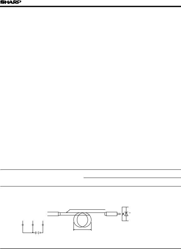
7 Measuring method of optical output coupling fiber |
|
|
|
|
|
|
|
|
|
|
|
|
|||||
|
|
|
|
|
|
Standard optical fiber cable |
|
|
|
|
|
|
|
|
|||
|
GP1F31T/GP1F32T/ |
|
|
|
|
|
|
|
Optical power |
|
|
|
|||||
|
GP1F33TT |
|
|
|
|
|
|
|
|
meter |
|
|
|
|
|||
|
Unit to be measured |
|
|
|
|
|
|
|
(Anritsu) ML93 |
|
|
|
|||||
|
|
|
|
|
|
|
|
|
|
|
|
|
|
|
|
|
|
Vin VCC GND
VCC
D
Note 1) VCC = 5.0 ± 0.05V (Operating )
2) To bundle up the standard fiber cable, make it into a loop with the diameter
The optical power meter must be calibrated to have the wavelength sensitivity of 660nm.
(0dBm = 1mW)
( D ) of 10cm or more.
 Loading...