


IS1U621/IS1U621L
IS1U621/IS1U621L |
Sensors for Remote Control |
|
■ Features
1. Compact
(Volume : About 1/8 compared with GP1U58X )
2.High sensitivity (Ultimate distance : MIN. 8 m)
3.B.P.F. (Band Pass Frequency) center frequency : (TYP. 38kHz)
■ Applications
1.Audio equipment
2.Cameras
■ Absolute Maximum Ratings |
|
(Ta=25˚C) |
|||
|
|
|
|
|
|
|
Parameter |
Symbol |
Rating |
|
Unit |
|
Supply voltage |
VCC |
0 to 6.0 |
|
V |
*1Operating temperature |
Topr |
- 10 to + 60 |
|
˚C |
|
|
Storage temperature |
Tstg |
- 20 to + 70 |
|
˚C |
*2Soldering temperature |
Tsol |
260 |
|
˚C |
|
*1 |
No dew condensation is allowed. |
|
|
|
|
*2 |
For 5 seconds at the position of 4.2 mm from the resin edge |
|
|
||
4.2mm |
3.1mm |
Soldering area |
Soldering area |
■ Outline Dimensions |
(Unit : mm) |
IS1U621 |
|
|
|
|
|
|
|
|
|
|
|
|
|
|
3.5 |
|
3.5 |
|
|
|
|
|
|
|
|
3.4 |
|
3.4 |
|
2.9 |
3.6 |
|
|
|
|
4.0 |
|
|
2.9 |
|
|
|
|
|
8.7 |
|
4.5 |
|
|
2.9 |
|
|
|
|
|
|
|
|
|
|
|
|
|
|
|
|
1.0 |
|
1.0 |
|
|
|
|
|
|
|
|
± |
|
|
|
|
|
|
|
||
|
21.0 |
|
|
1.0 |
0.4 -+ |
0.10.2 |
|
|
||
|
|
|
|
|
|
0.5 |
|
|
|
|
|
|
|
|
2.54 |
|
2.54 |
|
|
|
|
|
|
|
|
1 |
2 |
3 |
|
1 |
VOUT |
|
|
|
|
|
|
|
|
|
2 GND |
|
|
* |
Tolerance : ± |
|
0.2 mm |
|
|
|
3 |
VCC |
|
|
IS1U621L |
|
|
|
|
|
|
|
|
|
|
|
3.5 |
|
|
3.5 |
|
|
|
|
|
|
|
3.4 |
|
|
3.4 |
|
2.9 |
3.6 |
|
|
|
4.0 |
|
|
|
|
2.9 |
|
|
|
0.2 |
0.1 |
4.5 |
|
|
|
|
2.9 |
|
|
|
+ - |
|
|
|
|
|
|
|
|
0.4 |
|||
|
1 |
2 |
3 |
|
1.4 |
|
|
|
|
|
|
|
|
|
|
|
|
|
|
|
|
|
|
|
|
|
|
2.1 |
1.5 |
|
|
|
|
|
|
|
|
|
|
|
15.2 ± 1.0 |
|
|
|
|
|
|
|
|
|
|
1 |
VOUT |
|
|
|
|
|
|
|
|
|
2 GND |
|
|
* |
Tolerance : ± |
|
0.2 mm |
|
|
|
3 |
VCC |
|
|
|
|
|
|
|
|
|
||||
■ Recommended Operating Conditions
Parameter |
Symbol |
Recommended |
Unit |
|
operating conditions |
|
|||
Operating supply voltage |
VCC |
4.7 to 5.3 |
V |
|
|
|
|
|
|
“ In the absence of confirmation by device specification sheets, SHARP takes no responsibility for any defects that occur in equipment using any of SHARP's devices, shown in catalogs, data books, etc. Contact SHARP in order to obtain the latest version of the device specification sheets before using any SHARP's device”.
IS1U621/IS1U621L
■ Electrical Characteristics |
|
|
|
(Ta=25˚C, Vcc =+5V) |
|||
|
|
|
|
|
|
|
|
Parameter |
Symbol |
Conditions |
MIN. |
TYP. |
MAX. |
Unit |
|
Dissipation current |
ICC |
No input light, Output terminal OPEN |
- |
2.8 |
4.5 |
mA |
|
High level output voltage |
V OH |
*3, Output terminal OPEN |
VCC- 0.2 |
- |
- |
V |
|
Low level output voltage |
V OL |
*3, *4 |
- |
0.45 |
0.6 |
V |
|
High level pulse width |
T1 |
*3 |
400 |
- |
800 |
μ s |
|
Low level pulse width |
T2 |
400 |
- |
800 |
μ s |
||
|
|||||||
B.P.F. center frequency |
f O |
- |
- |
38 |
- |
kHz |
|
*5 Linear ultimate distance |
L |
Ee < 10 lx |
8.0 |
- |
- |
m |
|
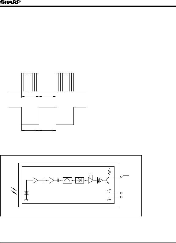
*3 The burst wave as shown in the following figure shall be transmitted. *4 Pull-up resistance : 2.2kΩ
*5 By SHARP transmitter
fo= 38kHz, Duty 50%
Transmission
signal
600μs 600μs
Output
T2 T1
■ Internal Block Diagram
|
|
|
|
Vout |
Limiter |
B.P.F. |
Demodulator |
Integrator |
Comparator |
|
|
|
|
Vcc |
|
|
|
|
GND |
 Loading...