


HOME CINEMA COMMAND
MODEL
HT-CN300W
OPERATION MANUAL
Thank you for purchasing this SHARP product. To obtain the best performance from this product, please read this manual carefully. It will guide you in operating your SHARP product.
HT-CN300W Home Cinema Command consisting of HT-CN300W (main unit), CP-CN300WF (front speakers), CP-CN300WC (centre speaker) and CP-CN300WR (surround speakers).
HT-CN300W
General Information - Special notes / Contents -
1
Special notes
Warning:
zWhen the ON/STAND-BY button is set at STAND-BY position, mains voltage is still present inside the unit. When the ON/STAND-BY button is set at STAND-BY position, the unit may be brought into operation by the timer mode or remote control.
zThis unit contains no user serviceable parts. Never remove covers unless qualified to do so. This unit contains dangerous voltages, always remove mains plug from the socket before any service operation and when not in use for a long period.
zThe supplied AC adaptor contains no user serviceable parts. Never remove covers unless qualified to do so. It contains dangerous voltages, always remove mains plug from the main outlet socket before any service operation or when not in use for a long period.
zTo prevent fire or shock hazard, do not expose this appliance to dripping or splashing. No objects filled with liquids, such as vases, should be placed on the apparatus.
Notes:
zThe letters in brackets contained in the model number indicate the colour of the product only. Operation and specifications are unaffected.
Contents
Page
„ General Information
Accessories . . . . . . . . . . . . . . . . . . . . . . . . . . . . . . . . . . . . . . . . . . . . . . . . . . . . . . . 2 Precautions . . . . . . . . . . . . . . . . . . . . . . . . . . . . . . . . . . . . . . . . . . . . . . . . . . . . . . . 3 Controls and indicators . . . . . . . . . . . . . . . . . . . . . . . . . . . . . . . . . . . . . . . . . . 4 - 6
„ Connections
Speaker connections . . . . . . . . . . . . . . . . . . . . . . . . . . . . . . . . . . . . . . . . . . . . . 7, 8 Aerial connection . . . . . . . . . . . . . . . . . . . . . . . . . . . . . . . . . . . . . . . . . . . . . . . . . . 8 Remote control sensor connection . . . . . . . . . . . . . . . . . . . . . . . . . . . . . . . . . . . . 8 Connecting other equipment . . . . . . . . . . . . . . . . . . . . . . . . . . . . . . . . . . . . . 9 - 11 Connecting to the AC socket . . . . . . . . . . . . . . . . . . . . . . . . . . . . . . . . . . . . . 12, 13
„ Speaker Installation
Placing the speaker system . . . . . . . . . . . . . . . . . . . . . . . . . . . . . . . . . . . . . . . . . 14 Installing the speakers on the wall . . . . . . . . . . . . . . . . . . . . . . . . . . . . . . . . . . . 15
„ Remote Control
Preparing the remote control . . . . . . . . . . . . . . . . . . . . . . . . . . . . . . . . . . . . . . . . 16 Operation buttons on the remote control . . . . . . . . . . . . . . . . . . . . . . . . . . 17 - 19 Memorising the remote control buttons . . . . . . . . . . . . . . . . . . . . . . . . . . . . 20, 21
„ Basic Operation
Setting the clock . . . . . . . . . . . . . . . . . . . . . . . . . . . . . . . . . . . . . . . . . . . . . . . . . . 22 Display control . . . . . . . . . . . . . . . . . . . . . . . . . . . . . . . . . . . . . . . . . . . . . . . . . . . 23 Sound control . . . . . . . . . . . . . . . . . . . . . . . . . . . . . . . . . . . . . . . . . . . . . . . . . . . . 23 Enjoy Surround Sound (sound mode) . . . . . . . . . . . . . . . . . . . . . . . . . . . . 24 - 26 Listening to the radio . . . . . . . . . . . . . . . . . . . . . . . . . . . . . . . . . . . . . . . . . . . . . . 27 Listening to a memorised station . . . . . . . . . . . . . . . . . . . . . . . . . . . . . . . . . . . . 28
„ Advanced Features
Speaker settings . . . . . . . . . . . . . . . . . . . . . . . . . . . . . . . . . . . . . . . . . . . . . . 29 - 31 Timer and sleep operation . . . . . . . . . . . . . . . . . . . . . . . . . . . . . . . . . . . . . . . 32, 33
„ References
Troubleshooting chart . . . . . . . . . . . . . . . . . . . . . . . . . . . . . . . . . . . . . . . . . . 34, 35 Error indicators and warnings . . . . . . . . . . . . . . . . . . . . . . . . . . . . . . . . . . . . . . . 35 Maintenance . . . . . . . . . . . . . . . . . . . . . . . . . . . . . . . . . . . . . . . . . . . . . . . . . . . . . 35 Specifications . . . . . . . . . . . . . . . . . . . . . . . . . . . . . . . . . . . . . . . . . . . . . . . . . . . . 36
02/7/11 HT-CN300W_A_1.fm
Accessories |
HT-CN300W |
|
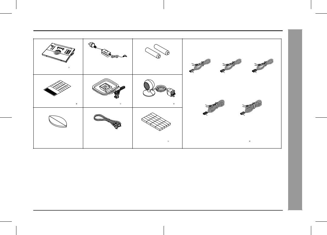
Please confirm that the following accessories are included.
|
|
|
(RADPA6006BGZZ) |
|
|
|
|
|
|
|
|
|
Remote control |
1 |
|
AC adaptor for remote control |
"AA" size battery (UM/SUM-3, |
|
|
|
|
||||
|
|
|
1 |
|
|
R6, HP-7 or similar) |
2 |
White |
Green |
Red |
|
|
|
|
|
|
|
|
|
|
|
|
|||
|
|
|
|
|
|
|
|
Front (left): |
Centre: |
Front (right): |
|
|
|
|
|
|
|
|
|
|
5 m (15') |
5 m (15') |
5 m (15') |
General Information |
|
Labels for remote control |
1 |
FM/AM loop aerial |
1 |
Remote control sensor |
1 |
|
|
- Accessories - |
||||
|
|
|
|
|
|
|
|
Blue |
Grey |
|||
|
|
|
|
|
|
|
|
Surround (left): |
Surround (right): |
|||
|
|
|
|
|
|
|
|
15 m (45') |
15 m (45') |
|||
Double-sided tape for remote |
Video cable |
1 |
|
Speaker cushion |
20 |
Speaker connection lead |
5 |
|||||
control sensor |
1 |
|
|
|
|
|
|
|
|
|
||
Note: |
|
|
|
|
|
|
|
|
|
|
||
|
|
|
|
|
|
|
|
|
|
|
|
|
Only the above accessories are included.
2
02/7/11 HT-CN300W_A_1.fm
HT-CN300W
General Information - Precautions -
3
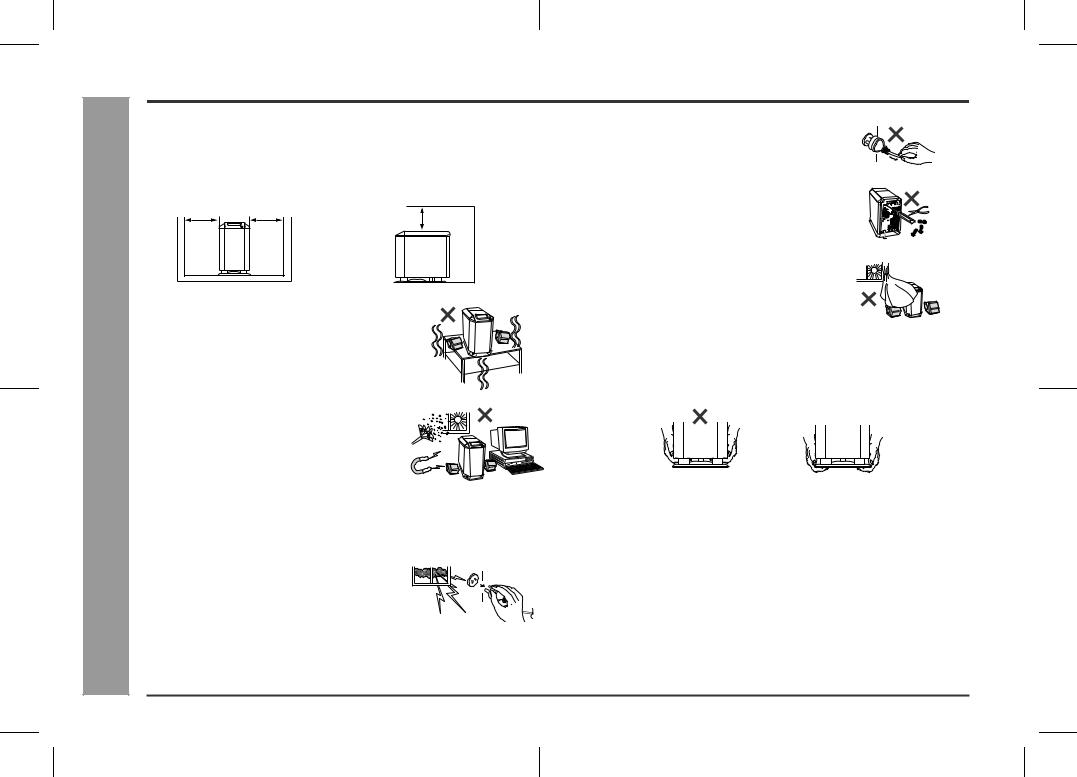
Precautions
„ General
zPlease ensure that the equipment is positioned in a well ventilated area and that there is at least 10 cm (4") of free space along the sides and back. There must also be a minimum of 15 cm (6") of free space on the top of the unit.
15 cm (6")
10 cm (4") 10 cm (4")

 10 cm (4")
z Use the unit on a firm, level surface free from vibration.
z Keep the unit away from direct sunlight, strong magnetic fields, excessive dust, humidity and electronic/electrical equipment (home computers, facsimiles, etc.) which generates electrical noise.
zDo not place anything on top of the unit.
zDo not expose the unit to moisture, to temperatures higher than 60°C (140°F) or to extremely low temperatures.
zIf your system does not work properly, disconnect the AC power lead from the wall socket. Plug the AC power lead back in, and then turn on your system.
zIn case of an electrical storm, unplug the unit for
safety.
z Hold the AC power plug by the head when removing it from the wall socket, as pulling the lead can damage internal wires.
z Do not remove the outer cover, as this may result in electric shock. Refer internal service to your local SHARP service facility.
z The ventilation should not be impeded by covering the ventilation openings with items, such as newspapers, tablecloths, curtains, etc.
zNo naked flame sources, such as lighted candles, should be placed on the apparatus.
zAttention should be drawn to the environmental aspects of battery disposal.
zThis unit should only be used within the range of 5°C - 35°C (41°F - 95°F).
zWhen carrying the unit by hand, do not hold the subwoofer located on the lower part. The subwoofer may be damaged.
Correct
Warning:
The voltage used must be the same as that specified on this unit. Using this product with a higher voltage other than that which is specified is dangerous and may result in a fire or other type of accident causing damage. SHARP will not be held responsible for any damage resulting from use of this unit with a voltage other than that which is specified.
„ Volume control
The sound level at a given volume setting depends on speaker efficiency, location, and various other factors. It is advisable to avoid exposure to high volume levels, to avoid this do not turn the volume on to full at switch on and listen to music at moderate levels.
02/7/11 HT-CN300W_A_1.fm
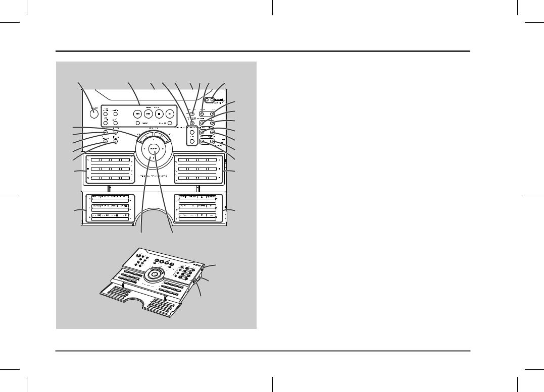
Controls and indicators
1 |
2 |
3 |
4 |
5 |
6 |
7 |
8 |
9 |
|
|
|
|
|
|
|
|
17 |
|
|
|
|
|
|
|
|
18 |
10 |
|
|
|
|
|
|
|
19 |
|
|
|
|
|
|
|
20 |
|
11 |
|
|
|
|
|
|
|
|
|
|
|
|
|
|
|
21 |
|
12 |
|
|
|
|
|
|
|
|
|
|
|
|
|
|
|
22 |
|
13 |
|
|
|
|
|
|
|
|
14 |
|
|
|
|
|
|
|
23 |
15 |
|
|
|
|
|
|
|
15 |
16 |
16 |
24 25
26
„ Remote control |
|
|
Reference page |
1. On/Stand-by Button . . . . . . . . . . . . . . . . . . . . . . . . . . . |
. . . . . . . . . . 13 |
2. Operation Buttons for Other Equipment . . . . . . . . . . . . |
. . . . . . . . . 18 |
3. Remote Control Transmitter . . . . . . . . . . . . . . . . . . . . . . |
. . . . . . . . . 16 |
4. Sound Mode Select Buttons . . . . . . . . . . . . . . . . . . . . . |
. . . . . . . . . 26 |
5. Dynamic Sound Select Button . . . . . . . . . . . . . . . . . . . . |
. . . . . . . . . 26 |
6. Remote Control Sensor for Learn Function . . . . . . . . . |
. . . . . . . . . 20 |
7. Speaker Set Up Button . . . . . . . . . . . . . . . . . . . . . . . . . . |
. . . . . . . . . 29 |
8. Clear Button . . . . . . . . . . . . . . . . . . . . . . . . . . . . . . . . . . . |
. . . . . . 21, 28 |
9. Learn Indicators . . . . . . . . . . . . . . . . . . . . . . . . . . . . . . . |
. . . . . . . . . 20 |
10.Volume Up and Down Buttons . . . . . . . . . . . . . . . . . . . . |
. . . . . . . . . 23 |
11.DVD Button . . . . . . . . . . . . . . . . . . . . . . . . . . . . . . . . . . . |
. . . . . . . . . 18 |
12.Video-1 Button . . . . . . . . . . . . . . . . . . . . . . . . . . . . . . . . . |
. . . . . . . . . 18 |
13.Tuner/Band Button . . . . . . . . . . . . . . . . . . . . . . . . . . . . . |
. . . . . . . . . 27 |
14.Video-2/Auxiliary Button . . . . . . . . . . . . . . . . . . . . . . . . |
. . . . . . . . . 18 |
15.Memory 1/2 Buttons for Other Equipment . . . . . . . . . . |
. . . . . . . . . 19 |
16.Label Sealing Area . . . . . . . . . . . . . . . . . . . . . . . . . . . . . |
. . . . . . . . . 21 |
17.Clock Button . . . . . . . . . . . . . . . . . . . . . . . . . . . . . . . . . . |
. . . . . . . . . 22 |
18.Memory Button . . . . . . . . . . . . . . . . . . . . . . . . . . . . . . . . |
. . . . . . . . . 28 |
19.Timer/Sleep Button . . . . . . . . . . . . . . . . . . . . . . . . . . . . . |
. . . . . . . . . 32 |
20.TV Screen Display Button . . . . . . . . . . . . . . . . . . . . . . . |
. . . . . . . . . 23 |
21.Dimmer Button . . . . . . . . . . . . . . . . . . . . . . . . . . . . . . . . |
. . . . . . . . . 23 |
22.Extra Bass/Demo Mode Button . . . . . . . . . . . . . . . . . . . |
. . . . . . 13, 23 |
23.Equaliser Mode Selector Button . . . . . . . . . . . . . . . . . . |
. . . . . . . . . 23 |
24.Cursor Button . . . . . . . . . . . . . . . . . . . . . . . . . . . . . . . . . |
22, 27, 29, 32 |
25.Enter Button . . . . . . . . . . . . . . . . . . . . . . . . . . . . . . . . . . |
. . . 22, 29, 32 |
26.Learn/Transmit Selector Switch . . . . . . . . . . . . . . . . . . . |
. . . . . . . . . 20 |
27.3.6 V DC Input Socket . . . . . . . . . . . . . . . . . . . . . . . . . . . |
. . . . . . . . . 12 |
28.Memory 1/2 Selector Switch . . . . . . . . . . . . . . . . . . . . . . |
. . . . . . 19, 20 |
27
28
HT-CN300W
Information |
and indicators - |
General |
- Controls |
|
|
4
02/7/11 HT-CN300W_A_1.fm
HT-CN300W
Information |
and indicators - |
General |
- Controls |
|
|
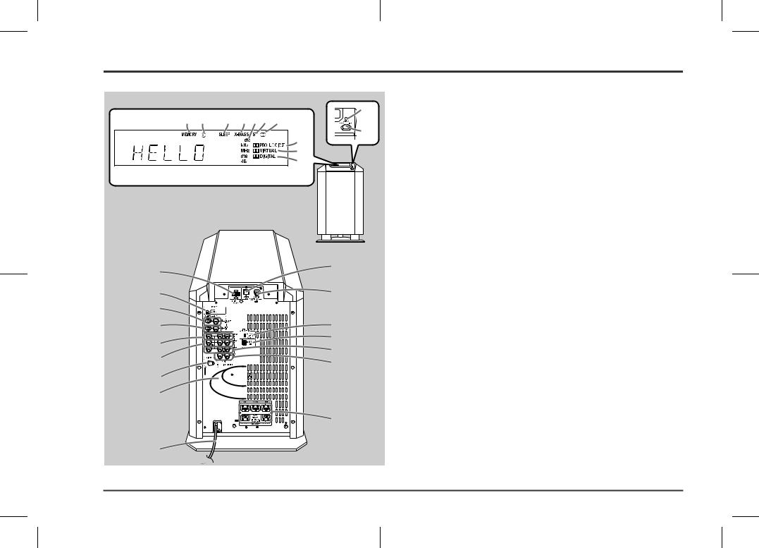
Controls and indicators (continued)
1 |
2 |
3 |
4 |
5 |
6 |
7 |
8
9
10
Front
Back
13
14
15
16
17
18
19
20
22
23
24
25
26
27
28
„ Main unit (with subwoofer)
11 |
1. Memory Indicator |
|
|
|
2. Timer Play Indicator |
123. Sleep Indicator
4.Extra Bass Indicator
5.Digital Theatre System Indicator
6.FM Stereo Mode Indicator
7.FM Stereo Receiving Indicator
8.Dolby Pro Logic II Indicator
9.Dolby Virtual Indicator 10.Dolby Digital Indicator
Reference page
11.Power Indicator . . . . . . . . . . . . . . . . . . . . . . . . . . . . . . . . . . . . . . . . .13 12.On/Stand-by Button . . . . . . . . . . . . . . . . . . . . . . . . . . . . . . . . . . . . . .13
13.Remote Control Sensor Socket . . . . . . . . . . . . . . . . . . . . . . . . . . . . |
.8 |
14.TV Type Switch . . . . . . . . . . . . . . . . . . . . . . . . . . . . . . . . . . . . . . . . . . |
11 |
15.TV Monitor Output Sockets . . . . . . . . . . . . . . . . . . . . . . . . . . . . . . . . |
10 |
16.DVD Video Input Sockets . . . . . . . . . . . . . . . . . . . . . . . . . . . . . . . . . |
10 |
17.Video and Audio Input Sockets (VIDEO 2) . . . . . . . . . . . . . . . . . . . |
11 |
18.Video and Audio Input Sockets (VIDEO 1) . . . . . . . . . . . . . . . . . . . |
11 |
19.AC Voltage Selector . . . . . . . . . . . . . . . . . . . . . . . . . . . . . . . . . . . . . . |
12 |
20.Subwoofer |
|
21.AC Power Lead . . . . . . . . . . . . . . . . . . . . . . . . . . . . . . . . . . . . . . . . . . |
12 |
22.DVD Optical Digital Audio Input Socket . . . . . . . . . . . . . . . . . . . . . . |
10 |
23.DVD Coaxial Digital Audio Input Socket . . . . . . . . . . . . . . . . . . . . . |
10 |
24.Span Selector Switch . . . . . . . . . . . . . . . . . . . . . . . . . . . . . . . . . . . . |
13 |
25.FM/AM Loop Aerial Socket . . . . . . . . . . . . . . . . . . . . . . . . . . . . . . . . |
.8 |
26.Video and Audio Output Sockets (VIDEO 1) . . . . . . . . . . . . . . . . . . |
11 |
27.Auxiliary Audio Input Sockets . . . . . . . . . . . . . . . . . . . . . . . . . . . . . |
11 |
28.Speaker Terminals . . . . . . . . . . . . . . . . . . . . . . . . . . . . . . . . . . . . . . . |
.8 |
21
5
02/7/11 HT-CN300W_A_1.fm
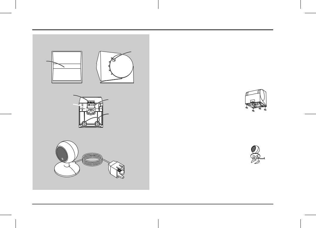
Front |
Side |
2
1
3 Bottom
5 4

 6
6
1 
2 

 3
3
„ Front/Centre/Surround speakers |
|
|
Reference page |
1. Full-Range Speaker |
|
2. Angle Adjusting Lever . . . . . . . . . . . . . . . . . . . . . . . . . |
. . . . . . . . . . 15 |
3. Label indication |
|
Front Speaker (right): Red |
|
Front Speaker (left): White |
|
Centre Speaker: Green |
|
Surround Speaker (right): Grey |
|
Surround Speaker (left): Blue |
|
4. Mounting Slot . . . . . . . . . . . . . . . . . . . . . . . . . . . . . . . . |
. . . . . . . . . . 15 |
5. Speaker Terminals . . . . . . . . . . . . . . . . . . . . . . . . . . . . |
. . . . . . . . . . . 8 |
6. Mounting Screw Holes . . . . . . . . . . . . . . . . . . . . . . . . . |
. . . . . . . . . . 15 |
Speaker cushion: |
|
Attach the cushions to the bottom of the speakers to prevent |
|
them from sliding. |
|
„ Remote control sensor |
|
|
Reference page |
1. Remote Sensor . . . . . . . . . . . . . . . . . . . . . . . . . . . . . . . |
. . . . . . . . . . 16 |
2. Remote Control Indicator . . . . . . . . . . . . . . . . . . . . . . . . |
. . . . . . . . . 16 |
3. Remote Sensor Connection Plug . . . . . . . . . . . . . . . . . |
. . . . . . . . . . 8 |
Double-sided tape for remote control sensor: |
|
You can fix the remote control sensor with the supplied tape. |
|
Caution:
zCarefully choose where you place the remote control sensor as the adhesive tape may damage or peel the surface coating when the tape is removed.
zNever locate the remote control sensor in an unstable place. Otherwise it may fall.
Note:
Fix the remote control sensor on a flat surface.
HT-CN300W
Information |
and indicators - |
General |
- Controls |
|
|
6
02/7/11 HT-CN300W_A_1.fm
HT-CN300W
Connections |
Speaker connections - |
|
- |
|
|
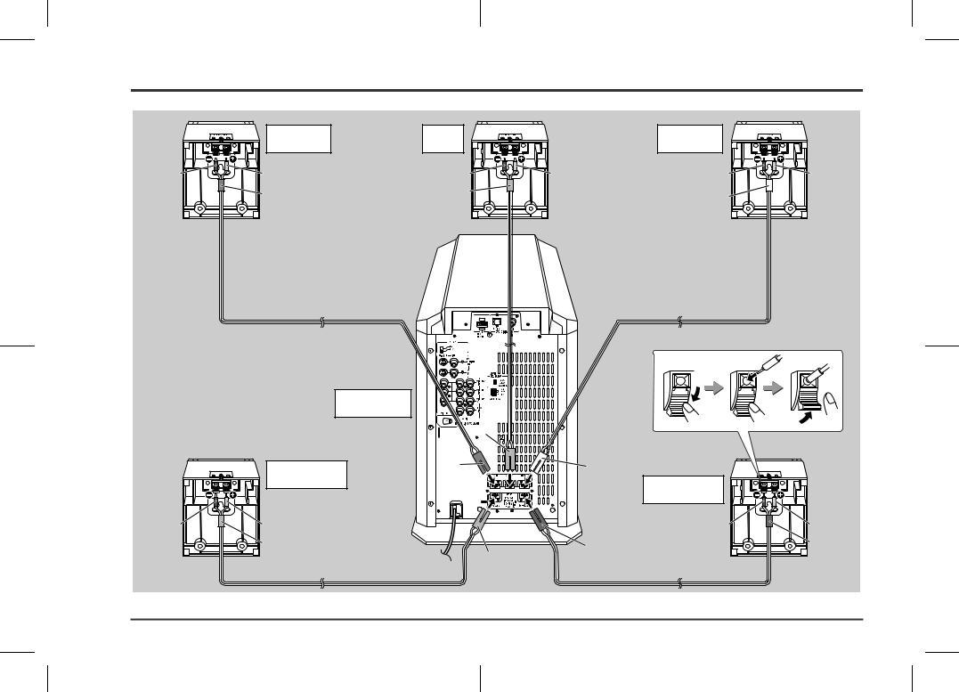
Speaker connections
|
Front speaker |
Centre |
|
Front speaker |
|
|
(right) |
speaker |
|
(left) |
|
Black |
Red |
Black |
Red |
Black |
Red |
|
Red |
Green |
|
White |
|
|
|
|
|
Main unit
(with subwoofer)
Green
Surround speaker |
Red |
White |
|
||
|
|
|
(right) |
|
Surround speaker |
|
|
|
|
|
(left) |
Black |
Red |
Black |
Red |
|
Grey |
Blue |
Blue |
|
|
Grey |
|
7
02/7/11 HT-CN300W_A_2.fm
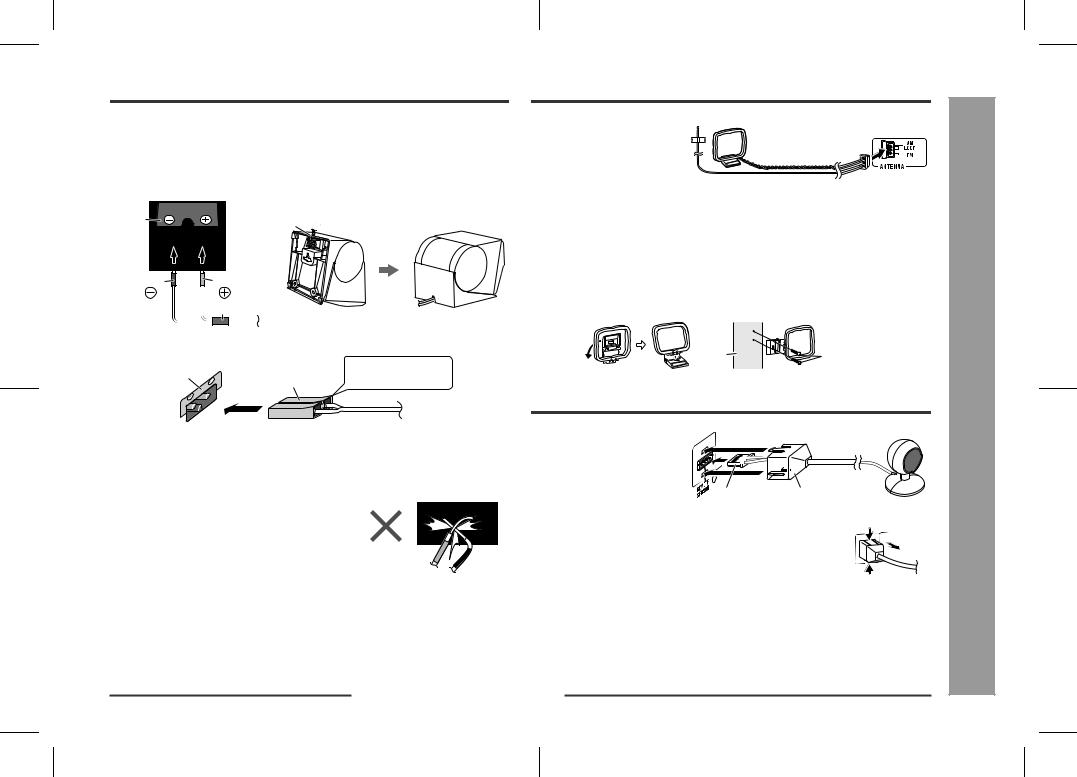
The speaker terminals on the main unit, the tube and plugs of the speaker lead, and speaker labels are distinguished by colour.
Connect the speaker and the unit by matching the colours. Connect the speaker wires to the speakers first, then to the unit.
Speaker
Label |
Recess |
Black |
Red |
Tube
Main unit
Label |
|
Plug in with the rising |
|
Speaker plug |
side facing up. |
||
|
Caution:
zOnly the supplied speakers should be used with this unit.
zMake sure to connect the speakers after unplugging the unit.
zDo not mistake  and
and  , and right and left terminals of the speaker leads.
zDo not let the bare speaker wires touch each other.
zDo not stand or sit on the speakers. You may be injured.
zInsert the speaker plug fully with the rising side facing up.
zHold the speaker plug when removing it from the unit. Pulling the lead may cause breakage.
Aerial connection |
HT-CN300W |
|
Connect the FM/AM loop aerial to the ANTENNA socket.
Position the FM aerial wire and rotate the AM loop aerial for optimum reception. |
|
||
Place the AM loop aerial on a shelf, or attach it to a stand or on a wall with screws |
|
||
(not supplied). |
|
- |
|
Notes: |
|
connections |
|
|
|
||
z Placing the aerial on the unit, or near the AC power lead or the remote sensor may |
|
||
cause noise pickup. Place the aerial away from the unit for better reception. |
|
||
z Do not connect the attached FM aerial to an external FM aerial. Otherwise, trouble |
|
||
may occur. |
|
|
|
Installing the AM loop aerial: |
|
|
|
< Assembling > |
< Attaching to the wall > |
Connections sensorcontrolRemote/ |
|
Wall |
Screws |
||
|
|||
(not supplied) |
|
||
|
|
||
Remote control sensor connection |
|
||
Connect the plug of the remote |
|
|
|
control sensor and push the plug |
|
|
|
cover until it clicks. |
|
Aerial/ |
|
Plug |
Plug cover |
||
Speaker- |
|||
Removing the remote control sensor: |
|
||
Push the upper and lower sides of the plug cover and take the Push |
|
||
plug off the unit to disconnect the remote control sensor. |
|
||
|
Push |
|
|
Caution:
zHold the connection plug of the remote control sensor when removing it from the unit. Pulling the lead may cause breakage.
zMake sure of the top and bottom of the plug when plugging in the remote control sensor.
8
02/7/11 HT-CN300W_A_2.fm

HT-CN300W
Connections |
Connecting other equipment - |
|
- |
|
|
Connecting other equipment
To enjoy images or music, connect other equipment to the main unit with the supplied video cable for TV or you can purchase commercially available cables.
Only one video cable is supplied with this unit.
TV
S-video cable
Video cable (supplied)
(See page 10.)
Camcorder,
Satellite receiver, etc.
Video cable
Audio cable (See page 11.)
Tape deck, etc.
Audio cable
(See page 11.)
Optical digital audio cable
or
Coaxial digital audio cable
|
DVD player |
S-video cable |
|
Video cable |
|
|
(See page 10.) |
Video cable |
|
Audio cable |
VCR |
|
|
Video cable |
|
Audio cable |
(See page 11.) |
Video cable: |
Audio cable: |
|
|
White (Left) |
White (Left) |
Yellow |
Yellow |
Red (Right) |
|
Red (Right) |
9
02/7/11 HT-CN300W_A_2.fm
Caution:
Turn off all other equipment before making this connection.
Notes:
zRefer to the operation manual of the equipment to be connected.
zInsert the plugs fully to avoid fuzzy pictures or noise.
„ Connecting the TV
Connect the TV to the main unit with the supplied video cable. If your TV has S-video input socket, connect the commercially available S-video cable to enjoy clearer images on DVDs.
Video cable (supplied) |
To video input socket |
TV |
S-video cable |
To S-video input socket |
Notes:
zChange the TV input in accordance with the connected socket.
zDo not connect other equipment between the TV and this unit. If they are connected via a VCR, pictures may be distorted.
zWhen the video and S-video cables are both connected, the images from the S- video input socket appears on your TV.
Caution:
The settings appear only when the TV is connected with a video cable. They will not appear when the TV is connected with an S-video cable.
During the tuner or auxiliary mode, the TV screen display will not be shown.
(See page 23 for the TV screen display.)
Example: TV screen display
„ Connecting the DVD player
Use the video cable or the S-video cable for receiving images. The S-video cable can realise clearer images. For audio, connect with the optical digital cable or the coaxial digital cable.
To connect to the video socket with the video cable:
Coaxial digital
audio cable
Optical digital audio cable
DVD player
Video cable |
To video output socket |
|
Note:
When connecting a DVD player with a video cable, be sure to use another video cable for the TV.
To connect to the S-video socket with the S-video cable:
Coaxial digital audio cable
Optical digital audio cable
DVD player
S-video cable To S-video output socket 
Note:
When connecting a DVD player with an S-video cable, be sure to use another S-video cable for the TV. This unit cannot convert the S-video signal into the video or other signals.
Switching the DVD audio input:
Switch the DVD's audio signal with the remote control according to the connected socket, "DIG1" (optical) or "DIG2" (coaxial) (see page 18).
Optical digital socket cap:
When using the optical digital socket, remove the cap first. After using the socket, replace the cap.
HT-CN300W
Connections |
Connecting other equipment - |
|
- |
|
|
10
02/7/11 HT-CN300W_A_2.fm
HT-CN300W
Connections |
Connecting other equipment - |
|
- |
|
|
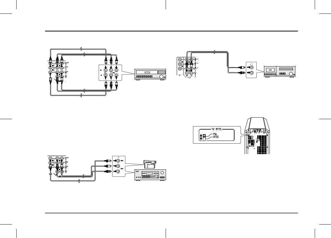
Connecting other equipment (continued)
„ Connecting the VCR (VIDEO 1) |
„ Connecting the tape deck, etc. (AUX) |
||
Video cable |
|
Audio cable |
|
|
|
||
Audio cable To video |
To audio |
To audio output sockets |
|
output socket |
output sockets |
||
Tape deck, etc. |
|||
|
|
||
|
|
VCR |
|
|
To video |
To audio |
Audio cable |
input socket |
input sockets |
Video cable |
|
|
Notes:
zConnect the unit and the TV with a video cable. The image of the equipment connected to the VIDEO 1 IN sockets does not appear on the TV even if it is connected with an S-video cable.
zThe image and sound are not emitted from the VIDEO 1 OUT sockets when the
equipment is connected to the DVD or VIDEO 1 IN sockets.
If connected to the VIDEO 2 IN sockets, they are emitted from the VIDEO 1 OUT sockets. If connected to the AUX IN sockets or whilst in the tuner mode, only the sound is emitted.
„Connecting the camcorder, satellite receiver, etc. (VIDEO 2)
To video |
Camcorder, |
output socket |
Satellite receiver, etc. |
Audio cable |
To audio |
|
Video cable |
||
output sockets |
Note:
Connect the unit and the TV with a video cable. The image of the equipment connected to the VIDEO 2 IN sockets does not appear on the TV even if it is connected with an S-video cable.
„ Selecting the colour TV system
There are two colour TV systems: PAL and NTSC.
Select either PAL or NTSC according to the TV connected.
To select the colour TV system:
Set the TV TYPE switch (on the rear panel) to PAL or NTSC.
Notes:
zThis unit can display on the TV its current speaker and mode settings when connected to the TV via a video cable in the DVD or VIDEO mode.
However, if TV TYPE is set to NTSC when PAL system TV is connected, or vice versa, the settings will not show correctly. (The display may show in black and white or may be distorted.) Set accordingly.
zSet the colour system (PAL/NTSC) of your DVD or VCR according to the connecting TV.
If the settings of TV, DVD/VCR and TV TYPE of this product do not match, pictures will not show correctly or will be scrambled.
11
02/7/11 HT-CN300W_A_2.fm
 Loading...