


 Loading...
Version 1.0
Produced in Mar. 2004
R
SSharp Programmable Controller
Model name Hand-held programmer JW-15PG
User's Manual
Thank you for purchasing the JW-15PG hand-held programmer for the Sharp programmable controller satellite W series.
This book (the user's manual) describes the operation of the JW-15PG.
Depending on the PLC model you are using, you may want to read this book together with the "Handling Manual for JW-14PG." Refer to the table below.
|
|
Reference manual |
|
|||
|
|
|
|
|
|
|
PLC model names |
Table of functions |
Operations |
|
|
||
Table of operation |
peculiar to |
|
Operation details |
|||
|
|
|||||
|
procedure |
JW300 |
|
|
||
|
|
|
|
|
|
|
JW300 |
|
This manual |
|
|
||
|
(Chapter 9) |
|
|
|||
|
|
|
|
|||
|
This manual |
|
|
|
|
JW-14PG |
JW50H/70H/100H, JW50/70/100 |
|
|
|
|
||
JW30H, JW20H, JW20, JW10 |
(Chapter 7, 8) |
|
|
|
|
instruction manual * |
|
|
|
|
|
|
|
J-board Z500 , J-board Z300 |
|
|
|
|
|
|
W100H, W70H, W100 |
|
|
|
|
|
|
W51, W16, W10 |
|
|
|
|
|
|
JW-32CV1/2/3 |
|
|
|
|
|
|
|
|
|
|
|
|
|
*If you are using the JW300 series, the descriptions are the same as for the JW-14PG, except for items marked "Operation specific to the JW300."
For other PLC models, all the operations are the same as for the JW-14PG.
To find the reference pages in the JW-14PG Handling Manual, see Chapter 8 in this manual.
-When using the JW300 or JW50H/70H/100H, set the MODE switches on the JW-15PG in order to match the PLC model you are using. => See page 4-2
Precautions
-When you plan to use SHARP programmable controllers (hereafter referred to as "PLCs"), you are requested to design each system so that even if a fault or malfunction occurs within the PLC, it will not lead to a serious accident in your system. You should incorporate back-up measures and fail-safe features in your system that will thoroughly protect your system from malfunctions if a fault or error occurs in the PLC.
-SHARP PLCs are designed and manufactured with the idea that they will be used in general applications in ordinary industries. Therefore, they must not be used in specific applications that can affect the health or safety of the public, such as nuclear power plants and other power generating plants. Such applications require a special warranty of quality that SHARP explicitly does NOT offer for these PLCs. However, if a user will certify that he/she does not requires a special quality warranty on the PLC, and will limit the use of the PLC to non-critical areas of these applications, SHARP will agree to such use.
If you are planning to use SHARP PLCs for applications that may affect the lives of human beings and property, and you need particularly high reliability performance, such as in the fields of aviation, medicine, transportation, combustion and fuel processing equipment, passenger cars, amusement park rides, and safety equipment, please contact our sales division so that we can confirm the required specifications.
Notes
-Though this manual is produced with the almost care, if you have any questions and inquiries, please feel free to contact our dealers.
-The whole or partial photocopy of this booklet is prohibited.
-Contents of this booklet may be revised for improvement without notice.
Safety Precautions
Read this manual and attached documents carefully before installation, operation, maintenance and checking in order to use the machine correctly. Understand all of the machine knowledge, safety information, and cautions before starting to use. In this instruction manual, safety precautions are ranked into "danger" and "caution" as follows.
Danger |
: Wrong handling may possibly lead to death or heavy injury. |
||
|
|
|
|
|
|
|
|
Caution |
: Wrong handling may possibly lead to medium or light injury. |
||
|
|
|
|
|
|
|
|
|
Even in the case of |
Caution |
, a serious result may be experienced depending on the |
|
|
|
points are mentioned. Be sure to observe them strictly. |
|
circumstances. Anyway, important |
||
The picture signs of prohibit and compel are explained below.
 : It means don’ts. For example, prohibition of disassembly is indicated as (
 ).
).
■ Installation
 Caution
•Use in the environments specified in the catalog and user's manual.
Electric shock, fire or malfunction may be caused when used in the environments of high temperature, high humidity, dusty or corrosive atmosphere, vibration or impact.
•Install according to the manual.
Wrong installation may cause drop, trouble or malfunction.
■ Use
 Danger
•Assemble the emergency stop circuit and interlock circuit outside of the programmable controller. Otherwise the machine breakdown or accident may be caused by the trouble of the programmable controller.
 Caution
•Manipulation for program change, forced output, run or stop during operation should be done with particular care by confirming safety. Misoperation may lead to machine trouble or accident.
•To avoid eye strain, rest your eyes 10 to 15 minutes every when working for long periods of time. Avoid continuous use for long periods of time.
■Maintenance
 Prohibit
•Don’t disassemble or modify.
Or fire, trouble or malfunction may be caused.
S-1

Chapter 1. |
Overview |
Chapter 2. |
Precautions for Use |
Chapter 3. |
System Configuration |
Chapter 4. |
Name and Function of Each Part |
Chapter 5. |
Connection/Installation Method |
Chapter 6. |
Specifications |
Chapter 7. |
Table of Functions |
Chapter 8. |
Table of Operation Procedure |
Chapter 9. |
Operating the JW300 |
Chapter 10. Table of Messages

|
Table of Index |
|
Chapter 1. Overview ............................................................................................................................................ |
1-1 |
|
Chapter 2. Precautions for Use ......................................................................................................................... |
2-1 |
|
(1) |
Installation and storage |
|
(2) |
Connection |
|
(3) |
Operation |
|
(4) |
Static electricity |
|
(5) |
Cleaning |
|
Chapter 3. System Configuration ............................................................................................................... |
3-1 to 2 |
|
Chapter 4. Name and Function of Each Part ............................................................................................ |
4-1 to 2 |
|
(1) |
Keypad |
|
(2) |
LCD unit |
|
(3) |
Retention screw |
|
(4) |
Connector |
|
(5) |
Connector mounting plate |
|
(6) |
Hand strap |
|
(7) |
Corresponding model label |
|
(8) |
MODE switch |
|
Chapter 5. Connection/Installation Method .............................................................................................. |
5-1 to 8 |
|
5-1 Changing the direction of the connector 5-1 |
||
5-2 Method for making cable connections |
5-2 |
|
[1]Connections to a control module in the JW300 series 5-2
[2]Connecting to the JW50H/70H/100H control module 5-3
[3]Connecting to the JW30H, JW20H, and J-board control modules (board) 5-4
[4]Connecting to the JW10 basic module 5-4
[5]Connecting to a module other than the control module 5-5
[6]Mounting to a control panel surface 5-7
5-3 Direct mounting method 5-8
Chapter 6. Specifications ............................................................................................................................ |
6-1 to 2 |
[1]General specifications 6-1
[2]Performance specification 6-1
[3]Dimensions 6-2
Chapter 7. Table of Functions ................................................................................................................... |
7-1 to 6 |
- Buzzer ON/OFF selection
7-1
- EL backlight ON/OFF selection
Index-1

-Contrast adjustment
-Auto repeat function
-Display mode selection
-Operation mode setting
-Menu selection
-Memory clear
-System memory (Read/Write)
-Enter program address
-Instruction entry method
-Program (Read/Write)
-Search program
-Modify program
-Edit program
-Check program
-Monitor program
-Monitor data memory
-Monitor break (debug function)
-Forced set/reset
-Read/write internal memory
-Change data memory
-Correct current register value
-Edit current register value
-Monitor process of I/O module
-I/O module monitor process
-Connect/remove I/O module live line
-I/O address assignment
-I/O module registration
-Set parameter
-Set clock
-Monitor clock
-Set parameter such as network module
-Remote programming and remote monitor
-Monitor target station number
-Device function
-Write program to EEPROM
-Read program to ROM
-Verify program with ROM
-Transfer to ROM writer
-SF monitor
-Symbol registration
-Monitor error
-Secret function
-OCT/DCML/HEX display of numerical value
-PC card
7-1
7-2
7-3
7-4
7-5
7-6
Index-2
Chapter 8. Table of Operation Procedure ............................................................................................... |
8-1 to 21 |
-Turn buzzer ON/OFF 8-1
-Turn EL backlight ON/OFF 8-1
-Adjust contrast 8-1
-Auto repeat function 8-1
-Change display mode 8-1
-Select operation mode 8-2
-Operation screen menu selection 8-2
-Clear memory 8-3
-Read/write system memory 8-3
-Set program address 8-4
-Enter basic and application instruction 8-4 to 5
-Enter application instruction 8-5
-Read/write program 8-5 to 6
-Search program 8-6 to 7
-Modify program 8-7
-Edit program 8-7 to 8
-Check program 8-8
-Monitor program 8-8
-Monitor data memory 8-9
-Break monitor (debug function) 8-10
-Forced set and reset 8-11
-Read/write internal memory with hexadecimal 8-11
-Change data memory 8-11
-Modify register current value 8-12
-Edit register current value 8-12 to 13
-I/O module monitor process (JW100H, etc.) 8-13
-I/O module monitor process [JW20H, JW30H, etc.] 8-14
-Connect/remove live line of I/O module 8-14
-Enter I/O address 8-15 to 17
-Parameter setting [JW20H, JW30H, etc.] 8-17
-Parameter setting [JW300] 8-17
-Set the clock 8-18
-Monitor time 8-18
-Set parameter for network module 8-18
-Remote programming 8-18
-Remote programming and remote monitor 8-19
-Monitor target station number 8-19
-Device function 8-19
-Write program to an EEPROM 8-19
-Read program from ROM 8-19
-Verify program with ROM 8-19
-Data transfer to ROM writer [JW20H, etc.] 8-19
-SF monitor [JW20H, etc.] 8-20
Index-3
-Symbol registration [JW20H, etc.] 8-20
-Monitor error 8-20
-Secret function (JW30H, etc.) 8-20
-Indicates the base notation (octal/decimal/hexadecimal) of the values specified 8-20
-PC card 8-21
Chapter 9. Operating the JW300 .............................................................................................................. |
9-1 to 19 |
9-1 Functions specific to the JW300 9-1
[1]Block programs 9-1
(1)Block move 9-3
(2)Start/end block (when a normal block is selected) 9-4
(3)Set/change the start relay (when a normal relay is selected) 9-5
(4)Refresh the I/O status display (when the main block is selected) 9-6
[2]PC card 9-7
(1)Save files 9-8
(2)Load files 9-9
9-2 Instructions specific to the JW300 9-10
[1]Basic instruction 9-10
(1)New instructions 9-10
(2)TNR/CNT instruction 9-11
[2]Index qualification 9-13
9-3 Additions and changes from conventional operations 9-14
[1]Display data memory 9-14
[2]Clear program memory 9-15
[3]Clear the file register 9-16
[4]Monitor program 9-16
(1)Monitor index register Z*** 9-16
(2)Monitor file register f******** 9-16
[5]Parameter setting 9-17
[6]Assigning I/O address 9-18
[7]Write and read programs to and from ROM 9-19
[8]Deleted functions 9-19
Chapter 10. Table of Messages ................................................................................................................ |
10-1 to 4 |
[1]Message seen while checking programs 10-1 to 2
[2]Error messages 10-3 to 4
Index-4

Chapter 1. Overview
The JW-15PG hand-held programmer (referred to as "programmer" in this manual) is a support tool for Sharp’s programmable controller. The programmer is designed for ease of use in maintenance, as well as for programming and monitoring the programmable controller.
The JW-15PG has added functions to the standard JW-14PG model, which are compatible with JW300 series PLCs.
-Display in two languages (Japanese/English), selectable.
-An EL backlight makes it easy to read in dark locations.
-Can display messages using the device function. Up to three steps can be displayed at once.
-Equipped with various monitor functions including freely selected multiple points, simultaneous monitoring of two stations, and data input/output.
-Equipped with a plenty of editing functions including programming, copying data memory, and batch processing of instructions.
-Includes with error message display functions.
1-1

Chapter 2. Precautions for Use
When using and storing JW-15PG, observe the following precautions.
(1)Installation and storage
1.Avoid installing the JW-15PG in a place where it will be exposed to:
-Area exposed to direct sunlight.
-Flammable gases permeate.
2.During storage, do not place anything on the JW-15PG.
(2)Connection
When connecting the JW-15PG to a control module of a programmable controller (hereafter referred to as "PLC") with a connection cable (option), keep the cable away from high voltage lines, motor lines, signal lines to the I/O module and power supply lines.
(3)Operation
1.Do not apply excessive force to the mounting screws or connectors.
2.Do not press the keypad with a sharp pointed object such as a pencil or ballpoint pen.
3.Keep the keypad away from welding sparks and hot solder.
4.If a malfunction or error (overheating, etc.) occurs in the JW-15PG, immediately stop operation, disconnect the cable or the control module from the JW-15PG and contact your dealer or our service company.
(4)Static electricity
In an extremely dry area, large amounts of static electricity may be generated in a person. Before touching the programmer, discharge any static electricity by first touching a grounded metallic object.
(5) Cleaning
Use a soft, dry cloth to clean the programmer. Use of volatile chemicals (alcohol, thinner, freon, etc.) or a wet cloth may cause deformation or discoloration.
2-1
Chapter 3. System Configuration
JW50H/70H/100H
JW50/70/100 control module
W16
W51, W100 W70H/100H control module
ZW-160CU ZW-501CU3 ZW-1K0CU ZW-1K1CU ZW-1K2CU ZW-1K3CU ZW-70CU ZW-1HCU
JW-50CUH JW-70CUH JW-100CUH JW-50CU JW-70CU JW-100CU
Remote I/O Network module ME-NET module slave module
ZW-20CM |
JW-20CM ZW-20CM ZW-30CM
ME-NET
JW-20MN ZW-20CM2
ZW-20RS |
JW-20RS ZW-20RS
I/O bus |
Serial interface |
|
expansion |
Ethernet module FL-net module |
|
adapter |
module |
JW-10SU |
JW-50CM |
JW-50FLT |
[JW-2EA] |
[JW-10SU] |
JW-50CM |
|
|
|
JW-50FL |
||
|
|
|
|
JW-51CM |
|
|
|
JW-52FL |
|
|
|
|
|
||||
|
|
|
|
|
||||
|
|
|
|
|
|
|
|
|
JW10
basic module
JW-1324K/1342K JW-1424K/1442K JW-1624K/1642K
JW300 control module
JW-311CU/312CU JW-321CU/322CU JW-331CU/332CU JW-341CU/342CU JW-352CU JW-362CU
Connection cable Connection cable
|
|
|
JW20H |
|
|
|
|
|
|
|
|
|
|
I/O bus |
||||
JW30H |
JW20 |
|
|
|
|
ME-NET |
FL-net |
expansion |
||||||||||
control module |
control module |
Network module module Ethernet module |
module |
adapter |
||||||||||||||
|
|
|
|
|
|
|
|
|
|
|
|
|
|
|
|
|
|
|
|
|
|
|
|
|
|
|
|
|
|
|
|
|
|
|
|
|
|
|
|
|
|
|
|
|
|
|
|
|
|
|
|
|
|
|
|
|
|
|
|
|
|
|
|
|
|
|
|
|
|
|
|
|
|
|
|
|
|
|
|
|
|
|
|
|
|
|
|
|
|
|
|
|
|
|
|
|
|
|
|
|
|
|
|
|
|
|
|
|
|
|
|
|
|
|
|
|
|
|
|
|
|
|
|
|
|
|
|
|
|
|
|
|
JW-31CUH/H1 |
|
JW-21CU |
[JW-22CM] [JW-21MN] [JW-255CM] |
JW-20FL5 |
[JW-32EA] |
|||
JW-32CUH/H1 |
|
JW-22CU |
|
|
|
JW-20FLT |
|
|
JW-33CUH/H1 |
|
|
|
|
|
JW-22FL5 |
|
|
|
H2/H3 |
|
|
|
|
|
JW-22FLT |
|
|
|
|
|
|
|
|
|
|
|
|
J-board |
|
|
- CPU board |
|
|
|
|
|
Z-311J, Z-312J |
|
|
|
Connection cable |
Z-511J, Z-512J |
|
|
|
- Satellite net board |
|
|
Z-335J |
|
|
|
|
|
- ME-NET board |
|
|
Z-334J |
|
|
- FL-net board |
|
|
Z-336J Z-336J2 |
|
|
- Ethernet board |
|
|
Z-339J |
|
|
|
|
|
|
|
|
|
|
|
|
|
|
|
|
JW-22KC (2 m) |
||
[JW-12KC (2 m)] |
[ZW-3KC (3 m)] |
||||||||||||||
JW-24KC (4 m) |
|||||||||||||||
|
|
|
|
|
|
|
|
|
|
|
|
|
|
|
|
|
|
|
|
|
|
|
|
|
|
|
|
|
|
|
|
Connection cable |
Hand-held |
[ZW-10C3 (1.8 m)] |
programmer |
|
|
AC adapter |
|
[ZW-10AC] |
|
W10 basic module |
|
|
[JW-15PG] |
VME built-in controller
JW-32CV1 JW-32CV2 JW-32CV3
-Direct installation
The JW-15PG can be installed directly in the following PLC models.
JW50H/70H/100H, JW50/70/100, W70H/100H => See "Chapter 5. Connection/Installation Method."
3-1
The following modules and cables can be connected to the JW-15PG.
■ Connection module
|
|
|
Module name |
|
Model name |
|||||
|
|
|
JW300 |
|
JW-311CU, JW-312CU, JW-321CU, JW-322CU, JW-331CU, JW-332CU, |
|||||
|
|
|
|
JW-341CU, JW-342CU, JW-352CU, JW-362CU |
||||||
|
|
|
|
|
|
|
||||
|
|
|
JW50H/70H/100H |
JW-50CUH, JW-70CUH, JW-100CUH |
||||||
|
|
|
JW50/70/100 |
JW-50CU, JW-70CU, JW-100CU |
||||||
|
module |
|
JW20H, JW20 |
JW-31CUH1, JW-32CUH1, JW-33CUH1, JW-33CUH2, JW-33CUH3, |
||||||
|
|
JW-21CU, JW-22CU |
|
|
||||||
|
|
|
JW30H |
|
JW-31CUH, JW-32CUH, JW-33CUH |
|||||
|
|
|
|
|
|
|
||||
|
Control |
|
|
|
|
|
|
|
|
|
|
|
JW10 |
|
JW-1324K, JW-1342K, JW-1424K, JW-1442K, JW-1624K, JW-1642K |
||||||
|
|
|
|
|||||||
|
|
|
W70H/100H |
ZW-70CU, ZW-1HCU |
|
|
||||
|
|
|
W100 |
|
ZW-1K0CU, ZW-1K1CU, ZW-1K2CU, ZW-1K3CU |
|||||
|
|
|
W51 |
|
ZW-501CU3 |
|
|
|||
|
|
|
W16 |
|
ZW-160CU |
|
|
|||
|
|
|
W10 |
|
ZW-28M124, ZW-28M114, ZW-28M111, ZW-28M122, ZW-28M324, |
|||||
|
|
|
|
ZW-28M424 |
|
|
||||
|
|
|
|
|
|
|
|
|
||
|
CPU board |
|
|
J-board |
Z-511J, Z-512J |
|
|
|||
|
|
|
|
|
|
|
||||
|
Z-311J, Z-312J |
|
|
|||||||
|
|
|
|
|
|
|
|
|
||
|
|
|
|
|
|
|
|
|
|
|
|
Network module |
JW-20CM, ZW-20CM, ZW-30CM |
||||||||
|
JW-22CM |
|
|
|||||||
|
|
|
|
|
|
|
|
|
||
|
ME-NET module |
JW-20MN, ZW-20CM2 |
||||||||
|
JW-21MN |
|
|
|||||||
|
|
|
|
|
|
|
|
|
||
|
Ethernet module |
JW-50CM, JW-51CM |
|
|
||||||
|
JW-255CM |
|
|
|||||||
|
|
|
|
|
|
|
|
|
||
|
|
|
|
|
|
|
|
|
|
|
|
FL-net module |
JW-50FL, JW-52FL |
|
|
||||||
|
|
|
|
|
||||||
|
JW-20FL5, JW-20FLT, JW-22FL5, JW-22FLT |
|||||||||
|
|
|
|
|
|
|
||||
|
|
|
|
|
|
|
|
|
||
|
Serial interface |
JW-10SU |
|
|
||||||
|
module |
|
|
|
||||||
|
|
|
|
|
|
|||||
|
|
|
|
|
|
|
|
|
||
|
Remote I/O slave |
JW-20RS, ZW-20RS |
|
|
||||||
|
module |
|
|
|
||||||
|
|
|
|
|
|
|||||
|
|
|
|
|
|
|
|
|
||
|
I/O bus expansion |
JW-2EA |
|
|
||||||
|
adapter |
|
JW-32EA |
|
|
|||||
|
VME built-in |
|
JW-32CV1, JW-32CV2, JW-32CV3 |
|||||||
|
controller |
|
||||||||
|
|
|
|
|
|
|||||
■ Connection cable |
|
|
|
|
||||||
|
|
|
|
|
|
|||||
|
Model name |
Cable length |
|
Remarks |
|
|||||
|
|
JW-22KC |
|
2 m |
|
Use for JW300, JW30H, JW20H, J-board (Z300/Z500), |
|
|||
|
|
JW-24KC |
|
4 m |
|
etc. |
|
|
||
|
|
ZW-3KC |
|
3 m |
|
Use for JW50H/70H/100H, etc. |
|
|||
|
|
JW-12KC |
|
2 m |
|
Use for JW10 |
|
|
||
|
|
ZW-10C3 |
|
1.8 m |
|
Use for W10 (ZW-10AC AC adapter is needed) |
|
|||
3-2

Chapter 4. Name and Function of Each Part
(3) Retention screw
 (2) LCD unit
(8) MODE switch
9 8 7
6 5
0 |
1 |
|
|
|
2 |
4 |
3 |
|
|
||
(1) Keypad
(3) Retention screw
(6) Hand strap
(7) Corresponding model label
Rating plate
(4) Connector
(5)Connector mounting plate 
-As for function of (1) to (8) => See next page
4-1

(1) Keypad |
|
|
For manipulating program writing, etc. |
[Key layout of the keypad] |
|
The key panel contains mode keys, control keys, in- |
Mode keys |
|
struction keys, and numeric keys. => See the figure |
||
|
||
on the right. |
|
|
|
Control keys |
|
(2) LCD unit |
|
|
The liquid crystal full dot matrix display (16 characters |
|
|
by 4 lines) shows instructions and data. The display is |
|
|
fitted with an EL backlight. |
|
|
(Display example) |
|
Instruction keys
F E D C B A 9 8 7 6 5 4 3 2 1 0
A N D |
|
0 |
0 |
0 |
0 |
1 |
|
|
O R |
N O T |
0 |
0 |
0 |
0 |
2 |
|
|
P 0 0 0 |
0 3 |
|
|
|
|
|
|
|
> S T R N O T |
0 |
0 |
0 |
0 |
3 |
Numerical value keys |
|
|
|
|
|
|
|
|
|
|
|
(3) Retention screw |
|
|
|
|
|
|
|
|
Used to secure the JW-15PG |
|
on a control module |
[Mounting example] |
|||||
(PLC) or control panel. |
|
|
|
|
|
|
|
|
|
|
|
|
|
|
|
|
ZW- |
|
|
|
|
|
|
|
|
IPU |
|
|
|
|
|
|
|
|
JW- |
|
|
|
|
|
|
|
|
70CU |
(4) Connector
Connects to a control module (PLC) or connection cable. The mounting direction can be changed.
(5) Connector mounting plate
The mounting direction of the connector can be changed for direct mounting of the programmer or for connection using the optional cable.
Hand strap
(6) Hand strap
Pass your hand through the strap when the programmer is connected via cable to prevent dropping it.
(7) Corresponding model label
This decal shows compatible PLC models and settings for the MODE switch.
(8) MODE switch
Used to select the PLC model you want to use and to change the display language (Japanese/English).
Setting value of |
1 |
2 |
3 |
|
|
4 |
MODE switch |
|
|
||||
|
|
|
|
|
|
|
Display |
Japanese |
English |
Japanese |
|
English |
|
(Japanese/English) |
|
|||||
|
|
|
|
|
|
|
|
JW300 |
|
|
|
|
|
|
|
|
|
|
||
|
JW50H/70H/100H |
JW50H/70H/100H |
||||
Corresponding |
(Unusable an expansion |
(Usable an expansion |
||||
relay) |
|
relay) |
|
|||
models (PLC) |
|
|
||||
JW30H, JW20H, JW20, JW10 |
|
|||||
|
|
|||||
|
J-board (Z300/500), JW50/70/100 |
|||||
|
W10/16/51/100, W70H/100H |
|
||||
MODE
9 |
0 |
1 |
|
8 |
|
||
7 |
|
|
2 |
6 |
4 |
3 |
|
5 |
|
||
(Setting when delivered : 1)
Note: Make sure to disconnect the cable from JW-15PG before setting the mode switch. Positions other than "1" to "4" cannot be used.
4-2
Chapter 5. Connection/Installation Method
This chapter describes the cable connections and installation of the JW-15PG.
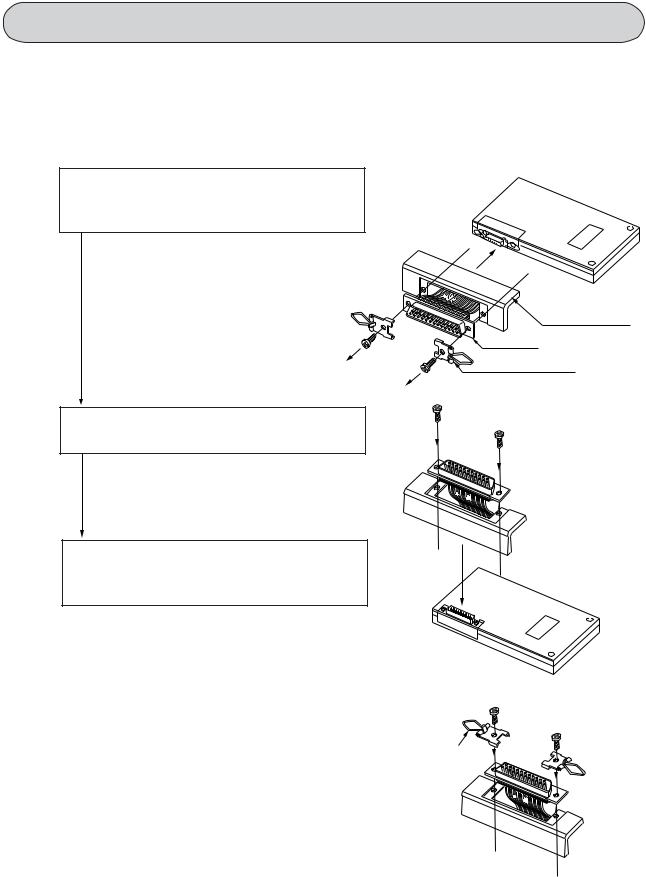
5-1 Changing the direction of the connector
The orientation of the cable connector on the JW-15PG can be changed as follows.
1)Remove the 2 screws securing the connector then detach the connector and connector mounting plate from the JW-15PG.
- Also remove the bail locks if attached.
Connector mounting plate
Connector |
Bail lock
2) Change the direction of the connector mounting plate.
3)Secure the connector and connector mounting plate to the programmer with the 2 screws.
Note: Do not attach the bail locks when di-
Bail lock
rectly mounting the programmer to the control module. The connectors will not contact properly if they are attached.
=> Refer to page 5-8
5-1
5-2 Method for making cable connections
This method is used to connect the JW-15PG to a PLC using cables (JW-24KC etc.: optional). This section describes the methods for connecting the following models.
JW300 |
=> [1] |
|
|
JW50H/70H/100H |
=> [2] |
|
|
JW30H, JW20H, J-board |
=> [3] |
|
|
JW10 |
=> [4] |
|
|
Modules other than control modules |
=> [5] |
|
|
Control panel (front face) |
=> [6] |
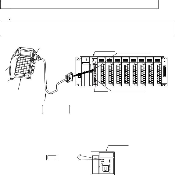
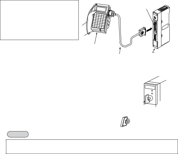
[1] Connections to a control module in the JW300 series
Connect a communication port (PG COMM1 or PG/COMM2) on a control module (JW-3**CU) to the JW-15PG.
1)Connect the JW-15PG to a control module using a JW-22KC/24KC cable.
2)Secure the cable using the bail locks on the JW-15PG and screws on the communication port connector.
Bail locks
JW-3**CU PG/COMM1 port
JW300
▲
PULL
PG/COMM1
This
battery expires
に行ってく ださい
Exchange the battery withinminutes.
PG/COMM2
Screw PG/COMM2 port
JW-15PG
Cable
JW-22KC (2 m)
JW-24KC (4 m)
[Reference] If you want to connect or disconnect the JW-15PG while the power to the JW300 remains ON, set the PROTECT switch on the control module to the ON position. When it is in that position, the program and system memory on the JW300 will be protected.
JW-3**CU
|
-> ON |
||
O |
|
|
PROTECT |
|
|
||
|
|
||
F |
|
|
|
F |
|
|
|
←
AUTO LD

 MW
MW
5-2
[2] Connecting to the JW50H/70H/100H control module
A common procedure is used to connect the programmer to the JW50H/70H/100H control module.
Connect the cable to the programmer’s connector and to the control module’s support tool connector. Firmly secure both the programmer’s end and the control module’s end of the cable with the bail locks.
Support tool connector
Programmer
(JW-15PG)
Control module
Cable (ZW-3KC)
[Reference]
-Set the memory protect switch to "ON" when connecting or disconnecting the programmer while the JW50H/70H/100H’s power is "ON." This protects the JW50H/70H/100H’s memory.
Notes
Control module 
Memory protect switch
ON (Input)
OFF (Output)
When the JW-15PG connected, a condition may occur where a "beep" is emitted and nothing is displayed. This occurs when the control module has been set to the device function.
5-3

[3] Connecting to the JW30H, JW20H, and J-board control modules (board)
A common procedure is used to connect the programmer to the control modules.
1)Connect the JW-15PG with the control module using the cable.
2)Secure the cable at the JW-15PG's end with the bail locks and at the control module’s end with the screws.
[Reference]
Set the PROTECT (memory protect) switch to "ON" when connecting or disconnecting the JW-15PG while the JW30H, etc.’s power is "ON." This protects the JW30H, etc.’s memory.
Notes
Support tool connector
Programmer (JW-15PG)
Cable
( JWJW--22KC24KC) JW-22CU
Memory module
Memory protect switch
ON 
(In case of JW20H)
When the JE-15PG is connected, a condition may occur where a "beep" is emitted and nothing is displayed. This occurs when the control module has been set to the device function.
[4] Connecting to the JW10 basic module
Connect the JW-15PG and basic module using connection cable JW-12KC.
Connect the cable with the JW-15PG using the bail locks. Connect the cable with the basic module using connector retention screws.
Basic module
Connector retention screw
Programer
(JW-15PG)
Connection cable (JW-12KC)
5-4
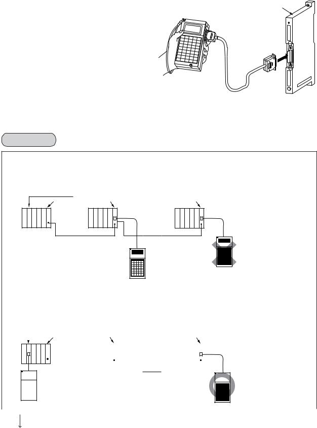
[5] Connecting to a module other than the control module
Installation methods of the JW-15PG are common for all the modules.
This section describes connection procedures to the JW-2EA I/O bus expansion adapter. The modules other than control modules are as follows:
- I/O bus expansion adapter: JW-2EA, JW-32EA => See the precautions below. - Network module: JW-20CM/22CM, ZW-20CM/30CM
- Remote I/O slave module: JW-20RS, ZW-20RS
- ME-MET module: JW-20MN/21MN, ZW-20CM2 - FL-net module: JW-50FL, JW-52FL,
JW-20FL5/T, JW-22FL5/T - Serial interface module: JW-10SU
-Satellite net board: Z-335J
-ME-NET board: Z-334J
-FL-net board: Z-336J, Z-336J2
-Ethernet module (board): JW-50CM, JW-51CM, JW-255CM, Z-339J
-VME built-in controller : JW-32CV1/32CV2 /32CV3
Precautions (Connect with JW-2EA or JW-32EA)
●In case of JW300
-Only one support tool at a time (JW-300SP, JW-15PG) can be connected to the JW-32EA.
[Example]
Control module |
|
JW-31EA JW-32EA |
JW-32EA |
Support tool
Support tool
-With the JW300, when one support tool (JW-300SP, JW-15PG) is connected to the control module, you can also connect another support tool to the JW-32EA.
[Example]
|
|
Control module |
|
JW-32EA |
JW-32EA |
|
|
|||||||||||||||||||||
|
|
|
|
JW-31EA |
|
|
||||||||||||||||||||||
|
|
|
|
|
|
|
|
|
|
|
|
|
|
|
|
|
|
|
|
|
|
|
|
|
|
|||
|
|
|
|
|
|
|
|
|
|
|
|
|
|
|
|
|
|
|
|
|
|
|
|
|
|
|
|
|
|
|
|
|
|
|
|
|
|
|
|
|
|
|
|
|
|
|
|
|
|
|
|
|
|
|
|
|
|
|
|
|
|
|
|
|
|
|
|
|
|
|
|
|
|
|
|
|
|
|
|
|
|
|
|
|
|
|
|
|
|
|
|
|
|
|
|
|
|
|
|
|
|
|
|
|
|
|
|
|
|
|
|
|
|
|
|
|
|
|
|
|
|
|
|
|
|
|
|
|
|
|
|
|
|
|
|
|
|
|
|
|
|
|
|
|
|
|
|
|
|
|
|
|
|
|
|
|
|
|
|
|
|
|
|
|
|
|
|
|
|
|
|
|
|
|
|
|
|
|
|
|
|
|
|
|
|
|
|
|
|
|
|
|
|
|
|
|
|
|
|
|
|
|
|
|
|
|
|
|
|
|
|
|
|
|
|
|
|
|
|
|
|
|
|
|
|
|
|
|
|
|
|
|
|
|
|
|
Support tool |
|
|
|
|
|
Support tool |
|
|
|
|
|
|
|
|
|
|
||
|
|
|
|
|
|
|
|
|
|
||
|
|
|
|
|
|
|
|
|
|
||
|
|
|
|
|
|
|
|
|
|
|
|
|
|
|
|
|
|
|
|
|
|
|
|
|
|
|
|
|
|
|
|
|
|
|
|
|
|
|
|
|
|
|
|
|
|
|
|
To the next page
5-5
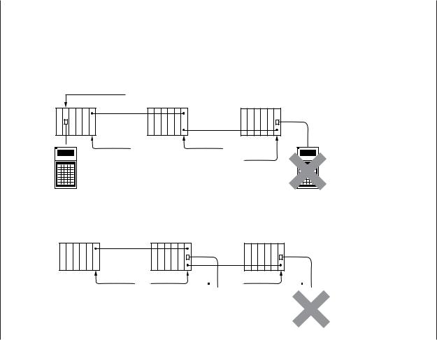
● In case of JW50H/70H/100H, JW30H
Only one support tool can be connected to the JW-2EA, JW-32EA. If a support tool is already connected to the control module or to another JW-2EA, JW-32EA, do not connect the programmer. Connecting the programmer will cause a malfunction.
[Example]
Control module
JW-1EA |
JW-2EA |
|
JW-2EA |
Support tool |
Support tool |
[Example]
JW-1EA |
JW-2EA |
JW-2EA |
|
|
|
|
|
|
|
|
|
|
|
|
Support tool |
|
|
|
|
|
|
|
|
|
|
|
Support tool |
|
|
|
|
|
|
|
|
|
|
|
|
|
|
|
|
|
|
|
|
|
|
|
||
|
|
|
|
|
|
|
|
|
|
|
|
|
|
|
|
|
|
|
|
|
|
|
||
|
|
|
|
|
|
|
|
|
|
|
|
|
|
|
|
|
|
|
|
|
|
|
||
|
|
|
|
|
|
|
|
|
|
|
|
|
|
|
|
|
|
|
|
|
|
|
||
|
|
|
|
|
|
|
|
|
|
|
|
|
|
|
|
|
|
|
|
|
|
|
|
|
5-6
[6] Mounting to a control panel surface
The programmer can be connected by cable and mounted apart from the PLC. For example, the PLC can be mounted in a control panel and the JW-15PG can be mounted to the door on the control panel.
200
87
62 15
45
190
(Unit: mm)
80×18 rectangular hole
49 |
2-M3 tap |
Make the M3 tapping holes used to secure the JW-15PG and a hole for the connector in the door on the control panel.
Mount the JW-15PG to the holes in the door on
the control panel. Retention screw 
Connect the cable to the JW-15PG’s connector and to the control module’s support tool connector. Firmly secure both the JW-15PG’s end and the network module’s end of the cable with the bail locks.
ZW-IPU
JW-70CU
Connection
cable
Notes
Keep the cable away from high voltage lines, power lines and the signal lines and power supply lines to the I/O module.
5-7

5-3 Direct mounting method
When JW50H/70H/100H, JW50/70/100, and W70H/100H PLC are used, you can install the JW-15PG directly on the control module. The method to connect the JW-15PG with the control module directly is shown below.
1) Detach the cover from the power supply |
Power supply |
Mounting |
module and fasten the programmer mounting |
bracket |
|
bracket with the bracket screw. |
module |
|
|
|
2) Attach the power supply module cover and |
Power supply |
Bracket |
detach the communication port cover. * |
screw |
|
module cover |
|
3)Connect the JW-15PG's connector to the control module’s support tool connector.
Programmer mounting screw
4) Tighten the 2 programmer mounting screws.
ZW-IPU
JW-70CU
Support tool connector
Communication |
port |
Reference
Set the memory protect switch to "ON" when mounting or dismounting the programmer while the JW50H/70H/100H, etc.’s power is "ON." This protects the JW50H/70H/100H, etc.’s memory.
Control module 
Memory protect switch
ON (Input)
OFF (Output)
*Detach the communication port connector cover when directly mounting the programmer to the JW70H/ 100H or JW70/100. Keep the detached cover.
Notes
-When the JW-15PG is connected, a condition may occur where a "beep" is emitted and nothing is displayed. This occurs when the control module has been set to the device function.
5-8

Chapter 6. Specifications
This chapter gives the general specifications and the performance specifications for the JW-15PG.
[1] General specifications
Items |
Specifications |
|
|
Ambient temperature |
Operation |
0 to 40oC |
|
Storage |
–20 to 60oC |
|
|
|
|
||
Ambient humidity |
Operation |
35 to 85% RH (non-condensing) |
|
|
|
||
Storage |
|
||
|
|
|
|
|
|
|
|
Ambient operating atmosphere |
Free from corrosive gas and dust. |
|
|
|
|
|
|
Vibration resistance |
Conform to JIS B 3502 |
|
|
(2 hours each in X, Y and Z axes) |
|
||
|
|
|
|
|
|
|
|
Shock resistance |
Conform to JIS B 3502 |
|
|
|
|
|
|
Consumption current |
110 mA |
|
|
|
|
|
|
Weight |
Approx. 400 g |
|
|
|
|
|
|
Accessories |
Bail lock set |
1 |
|
|
|
Programmer mounting bracket |
1 |
|
|
Programmer mounting bracket screw (M3x6) |
1 |
[2] Performance specification
Items |
|
Specifications |
|
|
- Control module |
- Ethernet module |
|
|
- Network module |
- FL-net module |
|
Modules to connect with |
- ME-NET module |
- VME built-in controller |
|
|
- Remote I/O slave module |
- J-board |
|
|
- I/O bus expansion adapter |
|
|
|
- Serial interface module |
* |
|
|
|
||
Connection method |
- Cable connection (for all module for connection listed above) |
||
- Direct mounting (JW50H/70H/100H, JW50/70/100, W70H/100H) |
|||
|
|||
|
|
||
|
Liquid crystal full dot matrix display (16 characters by 4 lines) |
||
|
- With EL backlight |
|
|
Display device |
(Auto OFF: Turns OFF: after about 10 minutes from the last key |
||
operation.) |
|
||
|
|
||
|
- Contrast adjustment (key operation) |
||
|
- Selectable between Japanese and English displays * |
||
Keys |
45 flat keys |
|
|
- Audible alarm is emitted at an invalid operation |
|||
|
- Key click sound is ON/OFF selectable |
||
|
|
|
|
* Use the MODE switches on the JW-15PG to set it for the model that it is connected to (and to change between Japanese/English). => Refer to page 4-2.
6-1
Loading...