


Sharp GP1U28Y, GP1U28X, GP1U27X, GP1U277X, GP1U273X Datasheet
...
GP1U26X/27X/28X/28Y Series
GP1U26X/GP1U27X Series
GP1U28X/GP1U28Y Series
Compact IR Detecting Unit for Remote Control
■ Features
1. Compact (case volume)
(GP1U28Y : About 1/4 compared with GP1U58Y)
2.Height from PWB to detector face same as GP1U58Y
3.Power filter capacitor and resistance are not required any more as a result of adoption of built-in constant voltage circuit
4.Various B.P.F. (Band Pass Frequency) frequency to meet different user needs
■Applications
1.AV equipment such as TV sets, VCRs and audio equipment
2.HA equipment such as air conditioners
■ Outline Dimensions
GP1U26X Series
|
7.3 |
|
|
|
+0.5 - 0.3 |
|
|
0.5 |
1.6 |
5.2 |
3.6 |
|
|
|
1.1 |
1.4 |
||||
|
|
|||||
|
|
|
|
|
||
|
|
3.4 |
26 |
|
|
2.8 |
10.2 |
|
*1 13.1 |
Marking |
|
1.4 |
|
|
|
|
|
|
S |
|
|
|
|
|
|
|
|
|
|
|
|
|
|
|
0.4 |
|
|
|
|
|
*1 |
|
|
|
*1 |
|
4 |
|
|
|
|
|
|
|
2.54 |
|
|
2.54 |
|
|
|
|
|
|
|
|
||
|
|
|
|
R1.9 |
Recommended drilling as viewed from the soldering face. |
||||||||
|
|
|
|
|
|
|
1.7 |
3.75 |
3.75 |
|
|
|
|
|
|
|
|
|
|
|
|
1.2 |
|
|
|
|
|
|
|
|
|
|
|
|
|
|
|
|
|
|
|
|
|
|
|
|
|
|
|
|
|
|
|
|
1.7 |
2-0.5 |
|
|
|
|
|
|
|
1.2 |
|
|
|
|
|
2-0.4 |
|
|
|
|
|
|
10.45 |
|
|
|
|
|
|
1 |
2 |
3 |
0.6 |
|
|
|
|
(9.7) |
|
|
8.75 |
||
0.6 |
|
|
|
|
|
|
|||||||
2-0.75 |
|
|
|
|
|
|
|
Detector |
|
|
|
|
|
|
|
|
|
|
|
|
|
center |
(0.5) |
|
|
|
|
|
1 Vout |
|
|
|
|
|
|
|
|
Φ |
|||
|
2 VCC |
|
|
|
|
|
|
|
|
||||
|
|
|
|
|
|
|
|
|
|
|
|
|
0. |
|
3 GND |
|
|
|
|
2.54 |
2.54 |
|
|
8 |
|||
|
|
|
|
|
|
|
|
||||||
|
|
|
|
|
|
|
|
|
|
|
|||
1. Unspecified tolerance : ± |
0.3 |
2. * |
1 : The dimension of lead base |
||||||||||
GP1U28X Series |
|
|
|
|
|
|
|
+0.5 |
0.3- |
||||
|
|
7.3 |
|
|
|
|
|
|
|
||||
|
|
|
|
|
|
|
|
|
|
|
|
|
|
|
|
0.5 |
|
|
1.6 |
|
|
14.4 |
3.6 |
1.1 |
1.4 |
||
|
|
|
|
|
|
|
|
|
|
|
|||
|
|
|
|
3.4 |
|
28 |
|
|
|
|
|
|
2.8 |
10.2 |
|
|
|
*1 13.1 |
|
|
Marking |
|
|
|
|
1.4 |
|
|
|
|
|
|
|
S |
|
0.4 |
|
|
|
|
|
|
|
|
|
|
|
|
|
|
|
|
|
|
|
*1 |
|
|
|
*1 |
|
4 |
|
|
|
|
|
|
|
2.54 |
|
|
2.54 |
|
|
|
|
|
|
|
|
||
|
|
|
|
R1.9 |
|
|
|
|
|
|
|
|
|
|
|
|
|
|
Recommended drilling as viewed from the soldering face. |
||||||||
|
|
|
|
|
|
|
1.7 |
3.75 |
3.75 |
|
|
|
|
|
|
|
|
|
|
|
|
1.2 |
|
|
|
|
|
|
|
|
|
|
|
|
|
|
|
|
|
|
|
|
|
|
|
|
|
|
|
|
|
|
|
|
1.7 |
|
|
|
|
1 Vout |
|
10.45 |
1.2 |
|
(9.7) |
|
|
8.75 |
|
|
|
|
|
2 VCC |
|
Detector |
|
|
|
||||
|
|
|
|
3 GND |
|
|
(0.5) |
|
|
|
|
||
|
|
|
|
|
|
center |
|
|
|
|
|||
2-0.5 |
|
|
|
|
|
|
|
|
|
|
|
|
|
2-0.4 |
|
|
|
|
|
|
|
|
|
|
|
|
|
2-0.75 |
|
|
|
|
|
|
|
|
|
|
Φ |
||
|
|
|
|
|
|
|
|
|
|
|
|||
|
1 |
2 |
3 |
|
|
|
|
|
|
|
|
0. |
|
0.6 |
0.6 |
|
|
|
2.54 |
2.54 |
|
|
8 |
||||
|
|
|
|
|
|
|
|
|
|||||
1. Unspecified tolerance : ± |
0.3 |
2. * |
1 : The dimension of lead base |
||||||||||
(Unit : mm)
GP1U27X Series
|
7.3 |
|
|
|
|
+0.5 -0.3 |
|
|
0.5 |
1.6 |
|
10.4 |
3.6 |
|
|
|
|
1.1 |
1.4 |
||||
|
|
|
|||||
|
|
|
|
|
|
||
|
|
3.4 |
27 |
|
|
|
2.8 |
10.2 |
|
*1 13.1 |
Marking |
|
|
1.4 |
|
|
|
|
|
|
|
|
|
|
|
|
|
S |
|
|
|
|
|
|
|
|
|
|
|
|
0.4 |
|
|
|
*1 |
|
|
*1 |
|
4 |
|
|
|
|
|
2.54 |
|
|
2.54 |
|
|
|
|
|
|
|
|
|
|
R1.9 |
Recommended drilling as viewed from the soldering face. |
||||||
|
|
|
|
|
|
1.7 |
3.75 |
3.75 |
|
|
|
|
|
|
|
|
|
1.2 |
|
|
|
|
|
|
|
|
|
|
|
|
|
1.7 |
|
|
|
1 Vout |
|
10.45 |
1.2 |
|
|
|
|
|
|
|
|
|
|
(9.7) |
8.75 |
|||
|
|
|
2 VCC |
|
Detector |
(0.5) |
||||
2-0.5 |
|
|
3 GND |
|
|
center |
|
|
||
2-0.4 |
|
|
|
|
|
|
|
|
|
|
2-0.75 |
|
|
|
|
|
|
|
|
|
|
0.6 |
1 |
2 |
3 |
|
|
|
|
|
|
|
|
|
0.6 |
|
|
|
|
|
|
Φ |
|
|
|
|
|
|
|
|
|
|
||
|
|
|
|
|
|
|
|
|
|
|
|
|
|
|
|
|
|
|
|
|
0. |
|
|
|
|
|
|
|
2.54 |
2.54 |
8 |
|
1. Unspecified tolerance : ± |
0.3 |
2. * |
1 : The dimension of lead base |
|||||||
GP1U28Y Series |
|
|
|
|
|
|
|
|
||
|
7.3 |
|
|
|
1.6 |
|
4 |
|
|
|
0.5
|
|
|
|
3.4 |
|
28S |
|
|
|
|
|
13 |
|
Marking |
|
|
|
|
|
3.6 |
0.4 |
|
|
|
|
|
|
|
|
|
|
|
1 |
2 |
3 |
|
1.6 |
|
1.4 |
0.6 |
0.6 |
|
3.7 |
1.4 |
|||
|
|
|
|
|
|
|
5.4 |
|
|
|
1 Vout |
|
|
6.8 |
|
|
|
|
|
|
|
|
|
|
2 VCC |
Recommended drilling as viewed from the soldering face. |
|||||
3 GND |
R1.9 |
|
2.54 |
2.54 |
||
|
|
|||||
|
|
|
|
|
.8 |
1.95 |
|
|
|
|
Φ |
0 |
|
|
|
|
|
|
||
|
|
|
|
|
|
|
|
|
3.65 |
|
|
|
1.7 |
|
|
1.7 |
|
|
|
|
0.5 |
|
1.2 |
|
1.2 |
||
|
|
|
|
|
|
|
*1 |
*1 |
|
3.75 |
3.75 |
|
|
2.54 |
2.54 |
|
|
|
||
1. Unspecified tolerance : ± 0.3 |
2. * |
1 : The dimension of lead base |
||||
“ In the absence of confirmation by device specification sheets, SHARP takes no responsibility for any defects that occur in equipment using any of SHARP's devices, shown in catalogs, data books, etc. Contact SHARP in order to obtain the latest version of the device specification sheets before using any SHARP's device”.
GP1U26X/27X/28X/28Y Series
■ Model Line-ups
Diversified models with a different B.P.F. frequency are also available.
B.P.F. center frequency |
|
Model No. |
|
Unit |
|
40 |
GP1U26X |
GP1U27X |
GP1U28X |
GP1U28Y |
|
36 |
GP1U260X |
GP1U270X |
GP1U280X |
GP1U280Y |
|
38 |
GP1U261X |
GP1U271X |
GP1U281X |
GP1U281Y |
|
|
|
|
|
|
kHz |
|
|
|
|
|
|
36.7GP1U262X GP1U272X GP1U282X GP1U282Y
32.75 |
GP1U263X |
GP1U273X |
GP1U283X |
GP1U283Y |
|
56.8 |
GP1U267X |
GP1U277X |
GP1U287X |
GP1U287Y |
|
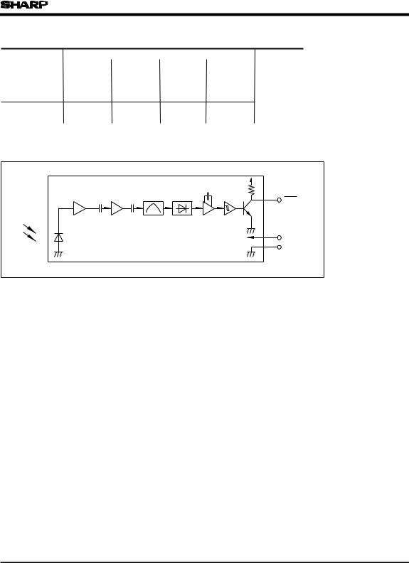
■ Internal Block Diagram
|
|
|
|
Vout |
Limiter |
B.P.F. |
Demodulator |
Integrator |
Comparator |
|
|
|
|
Vcc |
|
|
|
|
GND |
■ Absolute Maximum Ratings |
|
(Ta=25˚C) |
||
|
|
|
|
|
Parameter |
Symbol |
|
Rating |
Unit |
Supply voltage |
VCC |
|
0 to 6.3 |
V |
*1 Operating temperature |
Topr |
- |
10 to + 70 |
˚C |
Storage temperature |
Tstg |
- |
20 to + 70 |
˚C |
*2 Soldering temperature |
Tsol |
|
260 |
˚C |
*1 No dew condensation is allowed. |
|
|
|
|
*2 For 5 seconds |
|
|
|
|
■ Recommended Operating Conditions |
|
|||
|
|
|
|
|
Parameter |
Symbol |
Operating conditions |
Unit |
|
Supply voltage |
VCC |
4.7 to 5.3 |
V |
|
 Loading...