


Sharp GP1U58Y, GP1U587Y, GP1U583Y, GP1U582Y, GP1U581Y Datasheet
...
GP1U58Y Series
GP1U58Y Series
■ Features
1.Less sensitive to a fluorescent lamp driven by inverter
2.Various B.P.F. ( Band Pass Filter ) frequency
3.Built-in voltage regulator circuit
■ Applications
1.TVs
2.VCRs
3.Audio equipment
4.Air conditioners
5.CATV set top boxes
6.BS receivers
7.Multi-media equipments
IR Detecting Unit For
Remote Control
■ Outline Dimensions |
|
(Unit : mm ) |
||||||||
|
|
|
|
|
|
|
|
15 |
|
|
|
|
|
|
|
|
|
1 |
|
|
|
|
|
|
|
|
|
|
7.5 |
|
|
|
|
|
|
|
13.25 |
|
1 3.65 |
|
|
|
|
|
|
|
|
|
|
|
|
|
Rib |
|
|
|
|
|
1 |
Vout |
|
|
|
|
|
|
|
|
|
|
|
|
|
|
||
|
|
|
|
3.6 |
2 |
Vcc |
|
|
|
|
|
|
|
|
3 GND |
|
|
|
|||
|
|
|
|
|
1 2 |
3 |
|
|||
|
|
2 |
|
|
|
|
|
|
||
|
|
|
|
|
|
14.2 |
|
1.4 |
||
|
|
15.4 -+ |
0.30.5 |
|
|
|
|
|||
|
|
|
|
|
3 |
|
|
|
||
|
|
|
|
|
|
|
- |
|
|
|
|
|
|
|
|
|
2.4 |
φ |
|
|
|
|
|
|
|
|
|
0 |
|
|
|
|
|
|
|
|
|
|
. |
|
|
|
|
|
|
|
|
|
|
|
8 |
1 2 |
3 |
4.3 |
2 |
2.54 |
|
|
|
|
|
|
|||
|
|
|
|
|
2.54 |
|
|
|||
|
|
|
|
|
|
|
|
|
1.7 |
|
2 |
2.54 |
|
|
|
|
|
2.54 |
|
|
|
|
|
|
Recommended drilling as viewed |
|||||||
2 |
2.1 |
|
|
|
||||||
2 |
|
|
from the soldering face. |
|
|
|||||
|
|
5.5± 0.5 |
* |
|
Tolerance:± |
0.3mm |
|
|
|
|
|
|
|
|
|
|
|
||||
|
|
|
1 Detector center |
|
|
|
||||
|
|
|
2 The dimension of connector base |
|||||||
■ Absolute Maximum Ratings |
(Ta = 25˚C ) |
||
Parameter |
Symbol |
Rating |
Unit |
Supply voltage |
V CC |
0 to 6.3 |
V |
*1 Operating temperature |
T opr |
- 10 to + 70 |
˚C |
Storage temperature |
T stg |
- 20 to + 70 |
˚C |
*2 Soldering temperature |
T sol |
260 |
˚C |
*1 No dew formation |
|
|
|
*2 For 5 seconds |
|
|
|
■ Recommended Operating Conditions |
|||
|
|
|
|
Parameter |
Symbol |
Value |
Unit |
Supply voltage |
V CC |
4.7 to 5.3 |
V |
“ In the absence of confirmation by device specification sheets, SHARP takes no responsibility for any defects that occur in equipment using any of SHARP's devices, shown in catalogs, data books, etc. Contact SHARP in order to obtain the latest version of the device specification sheets before using any SHARP's device”.
GP1U58Y Series
■ Electrical Characteristics |
|
|
|
( Ta = 25˚C, VCC = + 5V) |
|||
|
|
|
|
|
|
|
|
Parameter |
Symbol |
Conditions |
MIN. |
|
TYP. |
MAX. |
Unit |
Dissipation current |
ICC |
No input light |
- |
|
- |
5.0 |
mA |
High level output voltage |
V OH |
|
V CC - 0.5 |
|
- |
- |
V |
Low level output voltage |
V OL |
*3 |
- |
|
- |
0.45 |
V |
High level pulse width |
T 1 |
400 |
|
- |
800 |
μs |
|
|
|
||||||
Low level pulse width |
T 2 |
|
400 |
|
- |
800 |
|
|
|
|
|||||
B.P.F. center frequency |
fO |
- |
- |
|
*440 |
- |
kHz |
*3 The burst wave as shown in the following figure shall be transmitted by the transmitter shown in Fig. 1. *4 Diversified models with a different B.P.F frequency, as shown in a separate table, are also available.
600 μ s |
600 μ s |
The value of fO is shown in a separate table.
Duty 50%
■ Model Line-up
Model No. |
B.P.F. frequency |
Unit |
|
GP1U58Y |
40 |
|
|
GP1U580Y |
36 |
|
|
GP1U581Y |
38 |
kHz |
|
GP1U582Y |
36.7 |
||
|
|||
GP1U583Y |
32.75 |
|
|
GP1U587Y |
56.8 |
|
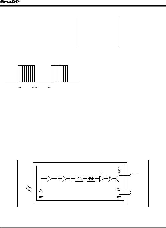
■ Internal Block Diagram
|
|
|
Vout |
Amp |
Limiter |
B.P.F. |
Demodulator Integrator Comparator |
|
|
|
Vcc |
|
|
|
GND |
 Loading...