


GR-55
Table of contents
 Loading...
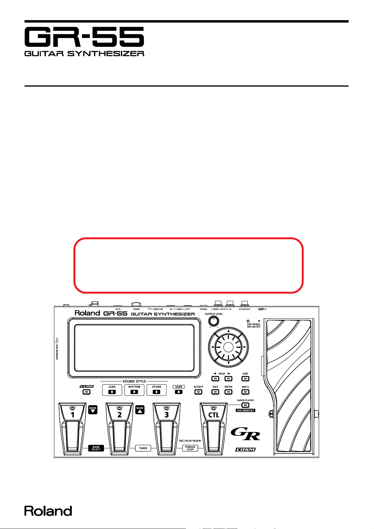
Jan. 2011 GR-55
SERVICE NOTES
Issued by RJA
Table of Contents
Cautionary Notes ..............................................................2
Specifications .....................................................................3
Location of Controls .........................................................4
Location of Controls Parts List........................................5
Exploded View ..................................................................6
Exploded View Parts List.................................................8
Assembling the USB Box..................................................9
Wiring Diagram/Block Diagram..................................10
Parts List ...........................................................................12
Verifying the Version......................................................14
Data Backup and Restore Operations ..........................14
Performing a Factory Reset............................................15
Updating the System ......................................................15
Test Mode.........................................................................16
Circuit Board (Main Board; no suffix)..........................20
Circuit Board (Main Board; suffix 1) ............................22
Circuit Diagram (Main Board: Power Block;
no suffix)...........................................................................24
Revise Information
Mar 16, 2011 p. 16 Corrected errors.
May 11, 2012 P.18 Added operations.
P.22, P.26, P.30, P.34 Circuit Boards and Circuit Diagrams.
May 7, 2013 P.12 Changed the category.
Circuit Diagram (Main Board: Power Block;
suffix 1) .............................................................................26
Circuit Diagram (Main Board: Analog Block;
no suffix)...........................................................................28
Circuit Diagram (Main Board: Analog Block;
suffix 1) .............................................................................30
Circuit Diagram (Main Board: Digital Block (SSC);
no suffix)...........................................................................32
Circuit Diagram (Main Board: Digital Block (SSC);
suffix 1) .............................................................................34
Circuit Diagram (Main Board: Digital Block (WSP)) .36
Circuit Diagram (Main Board: CTL Block)..................38
Circuit Board (Panel, Enc, EXP, GK Board).................40
Circuit Diagram (Panel, Enc Board) .............................42
Circuit Diagram (EXP Board) ........................................44
Circuit Diagram (GK Board)..........................................44
Circuit Board (Host Board) ............................................45
Circuit Diagram (Host Board) .......................................45
Copyright © 2011 Roland Corporation
All rights reserved. No part of this publication may be reproduced in any form without the written permission
of Roland Corporation.
CC-KWS17058718E0

Jan. 2011 GR-55
Cautionary Notes
Before beginning the procedure, please read
through this document. The matters described may
differ according to the model.
Back Up User Data!
User data may be lost during the course of the procedure. Refer to “Data
Backup and Restore Operations” (p. 14) in the Service Notes and save the
data. After completing the procedure, restore the backed-up data to the
product.
Part Replacement
When replacing components near the power-supply circuit or a heatgenerating circuit (such as a circuit provided with a heat sink or including a
cement resistor), carry out the procedure according to the instructions with
respect to the part number, direction, and attachment position (mounting so as
to leave an air gap between the component and the circuit board, etc.).
Parts List
A component whose part code is ******** will not be supplied as a service part
because one of the following reasons applies.
• Because it is supplied as an assembled part (under a different part code).
• Because a number of circuit boards are grouped together and supplied as
a single circuit board (under a different part code).
• Because supply is prohibited due to copyright restrictions.
• Because reissuance is restricted.
• Because the part is made to order (at current market price).
• Because it is carried in electronic data on the Roland web site.
• Because it is a package or an accessory irrelevant to the function
maintenance of the main body.
• Because it can be replaced with an article on the market. (battery or etc.)
Circuit Diagram
In the circuit diagram, “NIU” is an abbreviation for “Not in Use,” and
“UnPop” is an abbreviation for “Unpopulated.” They both mean non-mounted
components. The circuit board and circuit board diagram show silk-screened
indications, but no components are mounted.
2

Jan. 2011 GR-55
Specifications
GR-55: Guitar Synthesizer
Sound Generator
PCM: 2 tones
Modeling: 1 tone
Tones
PCM: 910 types
Modeling: 23 types (guitar mode)
17 types (bass mode)
Effects
MFX (Multi-Effects): 20 types
AMP (Preamp): 42 types
MOD (Modulation): 14 types
DELAY: 7 types
REVERB: 5 types
CHORUS: 4 types
EQ: 1 type
Patch Memory
Guitar mode
Preset: 270 + User: 297
Bass mode
Preset: 90 + User: 297
Connectors
GK IN connector (13 pins DIN type)
GUITAR OUT jack (1/4 inch phone type)
OUTPUT L/MONO, R jacks (1/4 inch phone type)
PHONES jack (Stereo 1/4 inch phone type)
MIDI connectors (IN, OUT) (5-pin DIN type)
USB COMPUTER connector (supports USB 2.0 Hi-Speed USB MIDI and USB
Audio)
USB MEMORY connector (supports USB 2.0 Hi-Speed Flash Memory)
DC IN jack
Power Supply
DC 9 V
Current Draw
700 mA
Dimensions
405 (W) x 244 (D) x 78 (H) mm
16 (W) x 9-5/8 (D) x 3-1/8 (H) inches
Maximum height:
405 (W) x 244 (D) x 106 (H) mm
16 (W) x 9-5/8 (D) x 4-3/16 (H) inches
AD Conversion
24-bit (GK Pickup)
24-bit + AF method (Normal Pickup)
* AF method (Adaptive Focus method)
This is a proprietary method from Roland & BOSS that vastly improves the
signal-to-noise (S/N) ratio of the A/D and D/A converters.
DA Conversion
24-bit
Sampling Frequency
44.1 kHz
Nominal Output Level
OUTPUT jacks: -10 dBu
GUITAR OUT jack: -10 dBu
Output Impedance
OUTPUT jacks: 2 kΩ
GUITAR OUT jack: 2 kΩ
USB Memory Audio Player
File Format: WAV, AIFF
Weight
3.3 kg / 7 lbs 5 oz (excluding AC adaptor)
Accessories
AC adaptor (#04236101)
AC cord (#02562456, #5100012293, #01903356, #5100018086, #03785590)
Owner’s manual (#5100018788)
Divided pickup (GK-3) (only for GK included model) (#********)
GK cable (5 m) (only for GK included model) (#********)
Options
Divided pickup: GK-3 (for guitar), GK-3B (for bass guitar)
GK cable: GKC-5 (5 m), GKC-10 (10 m)
MIDI foot controller: FC-300
Unit selector: US-20
* 0 dBu = 0.775 Vrms
* Printed matters will not be supplied after the end of the production. Then,
download the electronic file from the Roland web site.
* In the interest of product improvement, the specifications and/or appearance of
this unit are subject to change without prior notice.
Display
Graphic LCD 240 x 64 dots
3
Jan. 2011 GR-55
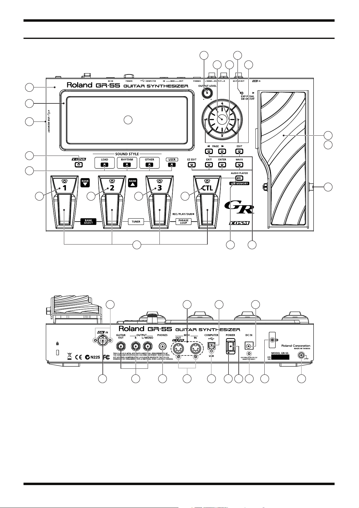
Location of Controls
fig.panel.eps
4 8
5 6
1
2
7
35
15
14
17 18 19 20
3
16
9
10
11
13 12
22
21 2423 30 33
25 27 31
26 28 3229 34
4

Jan. 2011 GR-55
Location of Controls Parts List
No. Part Code Part Name Description Q’ty
1 5100016592 TOP COVER 1
2 5100016594 ESCUTCHEON 1
3 5100016595 DISPLAY COVER 1
4 5100007869 R-KNOB INDEX G2477526R1 1
5100001448 POTENTIOMETER (F3279802R0) RD901F-40-125F-B50K-00D 1
5 5100016342 ENCODER KNOB (#G2477524R0) 1
01905467 ROTARY ENCODER EVE GC1 F20 24B 1
6 5100016340 CURSOR KEY A (#G2477528R0) 1
01780101 TACT SWITCH SKQKABD010 2
7 5100016341 CURSOR KEY B (#G2477527R0) 1
01780101 TACT SWITCH SKQKABD010 2
8 03349978 LED (RED) L-34HDSL-FPB 1
G2199514R0 LED SPACER 7MM 1
9 5100019136 VR PEDAL 1
10 5100016596 PEDAL PLATE 1
11 04560589 WASHER M6 T1 (H5039122) 2
04560590 U-NUT M6 BZC 1
5100002092 SCREW M6X70 (H5029867R0) HEX BOLT HALF THEREAD BZC 1
12 03344945 KEYTOP S (G2477513R0) 7
01780101 TACT SWITCH SKQKABD010 7
13 5100016347 S-KEYTOP SD1H BLK (#G2477510R0) 1
01780101 TACT SWITCH SKQKABD010 1
F5229819R0 LED (RED) L-7104SURC-E 1
H2369430R0 LED SPACER LEDS-1.5_KY 1
14 5100018778 S-KEYTOP SD5H CLR (#G2497019R0) 0.8
01780101 TACT SWITCH SKQKABD010 4
F5229819R0 LED (RED) L-7104SURC-E 4
H2369430R0 LED SPACER LEDS-1.5_KY 4
15 5100016347 S-KEYTOP SD1H BLK (#G2477510R0) 1
01780101 TACT SWITCH SKQKABD010 1
5100015704 LED L-7104QBC-H 1
H2369430R0 LED SPACER LEDS-1.5_KY 1
16 5100001928 SW PEDAL (G2187916R0) 4
5100002400 SW PEDAL ESCUTCHEON (#G2497024R0) 4
04560712 SUPPORT SPRING (G2177103R0) 4
5100011841 SW PEDAL FOOT H=7.2 (G2357140R0) 4
03344723 TACT SWITCH SKQKAKD010 4
17 5100016603 PEDAL LABEL 1 1
18 5100016604 PEDAL LABEL 2 1
19 5100016597 PEDAL LABEL 3 1
20 5100016598 PEDAL LABEL CTL 1
21 00564556 DIN TCS5093-10-4152 1
22 40237101 SCREW M3X8 PAN MACHINE W/SW+SMALL PW BZC 2
23 5100001342 6.5MM JACK HTJ-064-12IMP (13449155R1) 3
24 F3449714R0 6.5MM JACK HTJ-064-05A 1
25 13429825 MIDI CONNECTOR YKF51-5054V 1
26 40011312 SCREW 3X8 BINDING TAPTITE P FE BZC 2
27 5100017587 USB CONNECTOR UBR23-4K5100 1
28 40237101 SCREW M3X8 PAN MACHINE W/SW+SMALL PW BZC 1
29 12499175 BUTTON JSPUE0011A 1
30 5100018071 POWER SW ESCUTCHEON 1
31 F3439875R0 ADAPTOR JACK KM02018ABM1P 1
32 40019123 SCREW 3X8 BINDING TAPTITE S BZC 1
33 22365714 CORD HOOK 1
40019123 SCREW 3X8 BINDING TAPTITE S BZC 1
34 40679656 SCREW 4X8 BINDING TAPTITE S NI 1
35 5100018068 USB BOX CASE 1
5100018069 USB BOX COVER 1
40011312 SCREW 3X8 BINDING TAPTITE P FE BZC 2
5100006802 USB CONNECTOR UAS21-4K5J00 1
5
Jan. 2011 GR-55
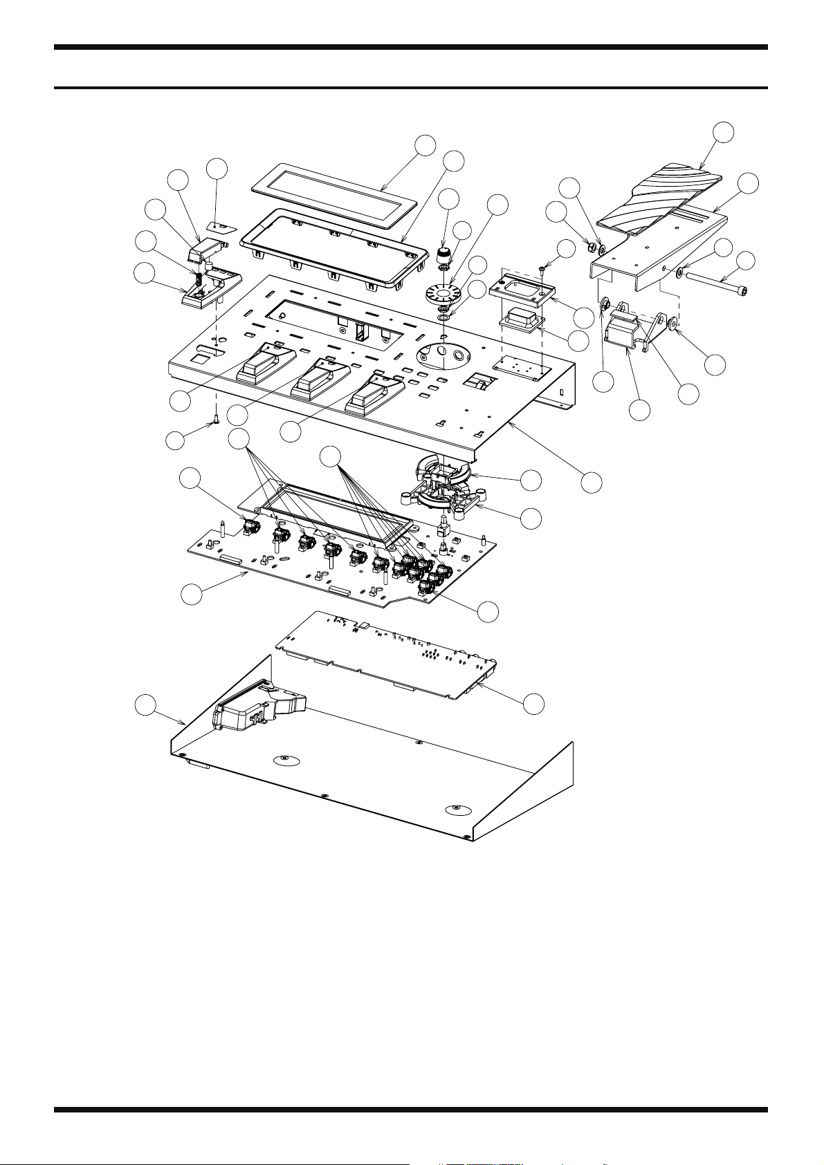
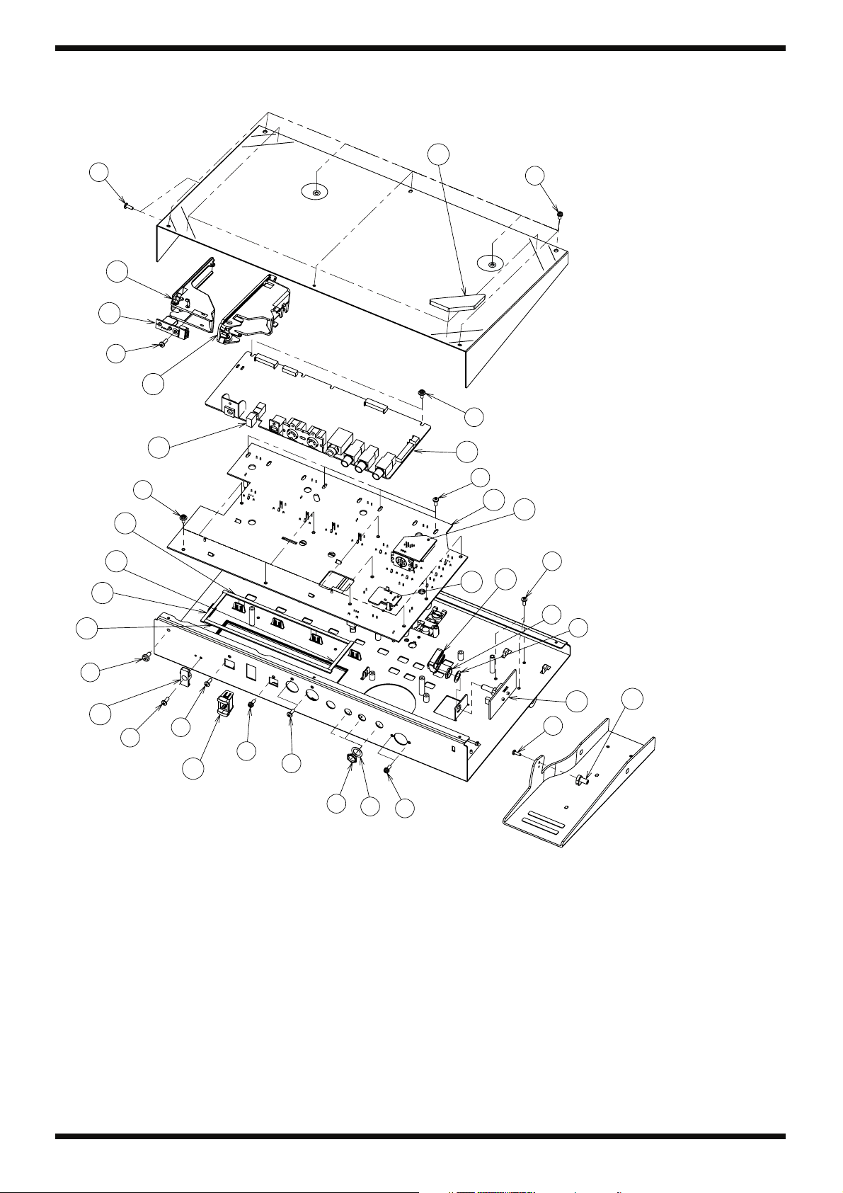
Exploded View
fig.bunkaizu.eps@L
29
28
30
27
32
i
22
31
33
20
34
21
4
9
3
8
b
a
19
b
25
l
o
p
c
e
15
14
16
16
13
10
24
1
23
39
22
2
37
6
Jan. 2011 GR-55
fig.bunkaizu.eps@R
35
j
6
38
i
5
h
f
17
26
h
37
i
39
41
17
18
11
18
d
36
e
e
g
7
j
m
n
g
42
e
o
p
40
k
12
7

Jan. 2011 GR-55
Exploded View Parts List
Parts
No. Part Code Part Name Description Q’ty
1 5100016592 TOP COVER 1
2 5100016593 BOTTOM COVER 1
3 5100016594 ESCUTCHEON 1
4 5100016595 DISPLAY COVER 1
5 5100018068 USB BOX CASE 1
6 5100018069 USB BOX COVER 1
7 5100018071 POWER SW ESCUTCHEON 1
8 5100019136 VR PEDAL 1
9 5100016596 PEDAL PLATE 1
10 5100002396 VR PEDAL HOLDER (G2147916R0) 1
11 03561356 SHAFT STAY STAY 1
12 5100016343 PIN STAY (#G1889117R0) 1
13 04560601 CUSHION R (#G2357111) 1
14 5100016344 RUBBER SW (#G2637107R0) 1
15 5100016345 RUBBER SW ESCUTCHEON (#G2567121R0) 1
16 04560634 BOLT HOLDER (G2147874) 2
17 5100016599 DISPLAY CUSHION A 2
18 5100016600 DISPLAY CUSHION B 2
19 5100007869 R-KNOB INDEX G2477526R1 1
20 5100018778 S-KEYTOP SD5H CLR (#G2497019R0) 0.8
21 03344945 KEYTOP S (G2477513R0) 7
22 5100016347 S-KEYTOP SD1H BLK (#G2477510R0) 2
23 5100016340 CURSOR KEY A (#G2477528R0) 1
24 5100016341 CURSOR KEY B (#G2477527R0) 1
25 5100016342 ENCODER KNOB (#G2477524R0) 1
26 12499175 BUTTON JSPUE0011A 1
27 5100001928 SW PEDAL (G2187916R0) 4
28 5100002400 SW PEDAL ESCUTCHEON (#G2497024R0) 4
29 04560712 SUPPORT SPRING (G2177103R0) 4
30 5100011841 SW PEDAL FOOT H=7.2 (G2357140R0) 4
31 5100016603 PEDAL LABEL 1 1
32 5100016604 PEDAL LABEL 2 1
33 5100016597 PEDAL LABEL 3 1
34 5100016598 PEDAL LABEL CTL 1
35 03344923 FOOT H=5 (G2357120) 4
36 22365714 CORD HOOK 1
37 5100015523 MAIN BOARD ASSY 1
38 5100018208 HOST BOARD ASSY 1
5100015524 PANEL SHEET ASSY 1
39 ******** PANEL BOARD 1
40 ******** EXP BOARD 1
41 ******** GK BOARD 1
42 ******** ENC BOARD 1
* This unit includes the following parts.
Screws
No. Part Code Part Name Description Q’ty
a 5100002092 SCREW M6X70 (H5029867R0) HEX BOLT HALF THEREAD BZC 1
b 04560589 WASHER M6 T1 (H5039122) 2
c 04560590 U-NUT M6 BZC 1
d 40679656 SCREW 4X8 BINDING TAPTITE S NI 1
e 40019123 SCREW 3X8 BINDING TAPTITE S BZC 7
f 40342956 SCREW M3X6 PAN MACHINE W/SW+PW(S) BZC 8
g 40237101 SCREW M3X8 PAN MACHINE W/SW+SMALL PW BZC 3
h 40012867 SCREW M3X8 PAN MACHINE W/SW+PW ZC 14
i 40011278 SCREW 3X8 BINDING TAPTITE P FE ZC 8
j 40011312 SCREW 3X8 BINDING TAPTITE P FE BZC 6
k 40233012 SCREW 2.6X8 BINDING TAPTITE P BZC 1
l 40128923 HEX NUT M7 1
m 5100003918 JACK NUT M9X12X2 NI RTC(H5039510R0) 3
n 5100003926 PLAIN WASHER 9X13.5X0.5T NI(H5039158R0) 3
o H5069001R0 NUT M9 1
p H5039126R0 M9 WASHER 1
8
Jan. 2011 GR-55
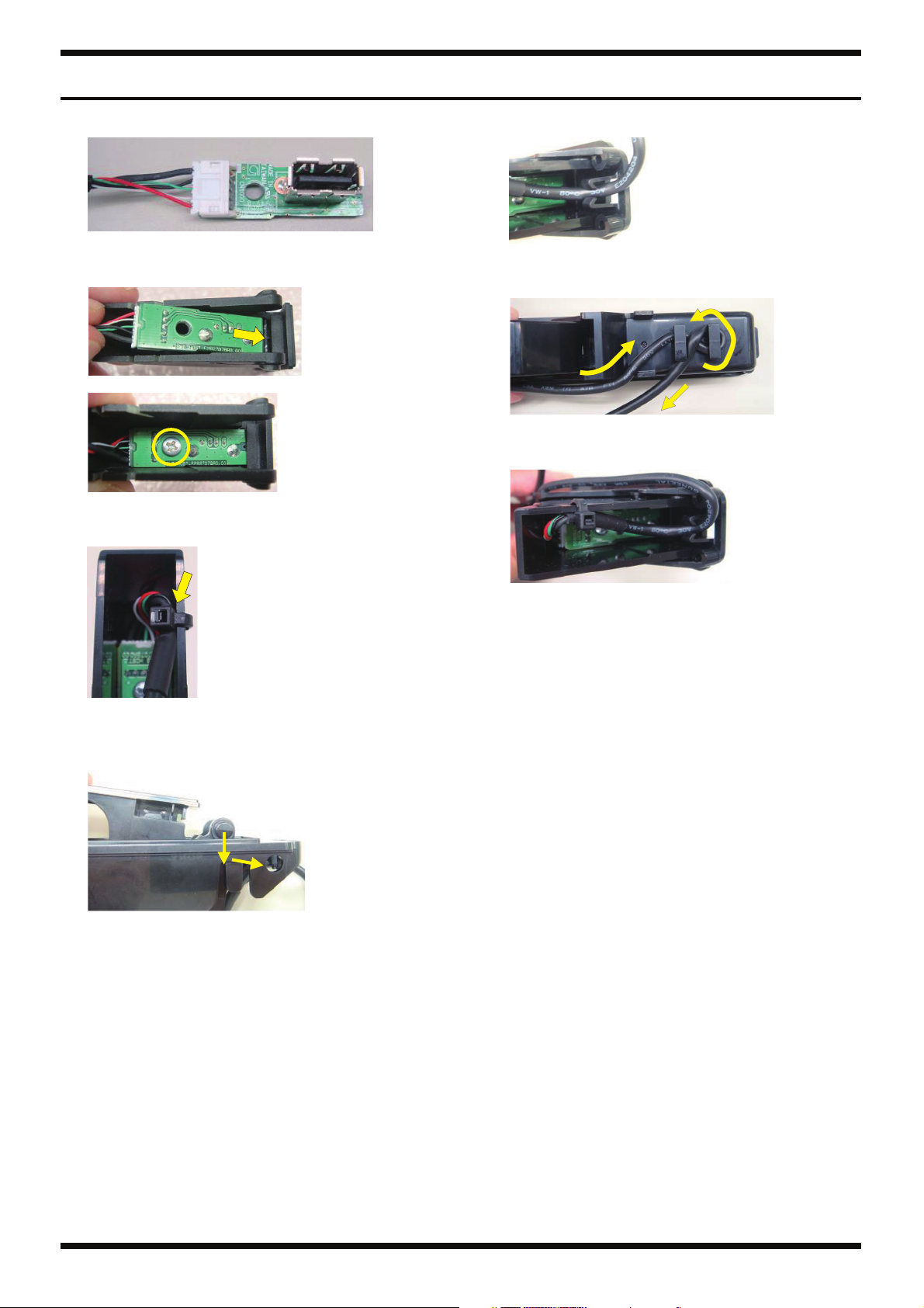
Assembling the USB Box
1. Connect Wiring W4 (#5100017066) to the Host Board Assy (#5100018208).
fig.assemble-1.eps
2. Assemble the Host Board Assy to the USB Box Cover (#5100018069), and
secure in place using Screw 3 x 8 Binding Taptite P FE ZC (#40011278).
fig.assemble-2.eps
fig.assemble-3.eps
3. Secure Wiring W4 in place using a cable tie, and fit it securely into the
USB Box Cover.
fig.assemble-4.eps
5. Secure Wiring W4 to the tab on the USB Box Case.
fig.assemble-6.eps
6. Engage Wiring W4 on the hooks on the USB Box Case and adjust the
shape.
fig.assemble-7.eps
7. After winding, check to ensure that Wiring W4 will not come loose from
the tab.
fig.assemble-8.eps
4. Fit the USB Box Cover into the USB Box Case (#5100018068).
After pressing in downward, press in at an angle, then fit the protrusion
on the USB Box Cover into the hole in the USB Box Case.
fig.assemble-5.eps
9
Jan. 2011 GR-55
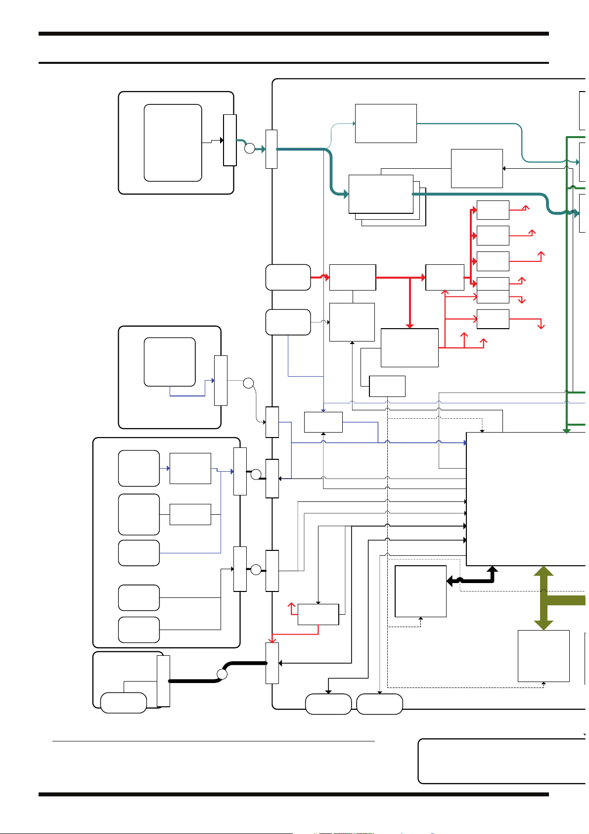
Wiring Diagram/Block Diagram
fig.block-wiring.eps@L
MAIN BOARD
IC42
AF
(Invert)
IC33,35,38
Buffer
IC9
IC9
(Invert)
Buffer
Buffer
3.3V,1.2V,-9V
SYS-RST
IC9,16
RESET
JK2
MIDI I/O
FET SW
(A-PWR)
IC1
DC-DC
SCL-COM,LED(PORT)
MPX-SEL(PORT)
SW(PORT)
ENC(PORT)
UP,UD,UHVB,OC
VBUS,UP,UD
IC11
NOR Flash
512Mb
(Wave)
IC34,36,39
IC32
GK SENS
Q4
-9V
D+3.3
D+1.2
SCL-COM,GAIN(PORT)
XRST
AN0-3
PF2,3
PF2,WAHH6
WAHH0,1,7
AHP7,8,9,11
PF8,9
UH,PF6,7
UF
UART
P0,1
IC23
+3.3V
IC4
+5V
IC2
+7V
Q19
Q18
IC3
-7V
XPWR-OFF
PF4
A+3.3
D+5/
A+5
A+7V
A+PH/
A-PH
A-7V
IC10
SSC
IC8
NOR Flash
64Mb
(Program)
SW
(PA NEL)
LED
PANEL BOARD
VR500
EN500
SW
(PEDAL)
JK1000
USB HOST
EXP BOARD GK BOARD
JK8
GK IN
VR501
C
N
1
0
0
0
IC500
SW MPX
IC501
S->P Drv
C
N
4
C
N
WIRING 3P
5
0
3
3
W4 (5pin-Shield)
C
2
N
3
W3
GK-SW,VOL
JK1
DC IN
Q1
FET SW
(POWER)
Q25,31
SW1
POWER
Tr
(V-DET,
SOFT-SW)
XSWD-PWR
4
C
N
2
IC24
MPX
C
N
5
0
0
W1
C
1
N
1
C
N
5
0
5
W1
C
1
N
5
D+5V
IC22
HS-SW
C
N
8
JK3
USB Func
WCD0-7,13
A[1-22]
D[0-15]
CS0
No. Part Code Part Name Description Q’ty
1 5100017063 WIRING W1 2
2 5100017065 WIRING W3 1
3 5100017066 WIRING W4 1
4 5100002340 WIRING 3P 1
10
LCD
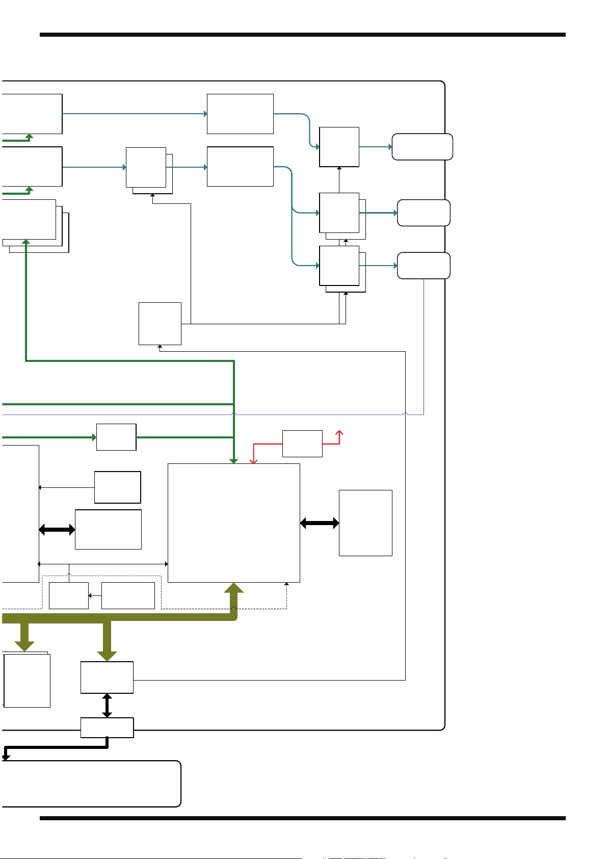
Jan. 2011 GR-55
fig.block-wiring.eps@R
IC41
DAC
AK4386
IC45
CODEC
AK4556
IC31,37,40
ADC
IC10
IC10
AK5357
ADC
ADC
SSC->WSP(4ch)
SSC->GUITAR OUT(2ch)
SSC->OUTPUT(2ch)
GK-IN->WSP(6ch)
MUTE
WSP->SSC(6ch)
IC21
LATCH
Q5,7
Q??
MUTE
Q14,15,16
MUTE
CTL
SSC->WSP(4ch)
IC43
Buffer
(Differencial)
IC47
Buffer
(Invert)
XMUTE-OUTPUT
D+1.5
PH-DET
IC7
+1.5V
Q17
MUTE
Q20,21
Q??
MUTE
MUTE
Q22,24
Q??
MUTE
MUTE
D+3.3
JK10
GUITAR OUT
JK8,9
OUTPUT
JK11
PHONES
IC4,7
IC14,15
SDRAM
SDRAM
64Mb*2
128Mb*2
ERAM_IF
CKUDL
A[2-16]
D[0-31]
CS3
CKUSB
IC12
BUFFER
IC5
OSC
48MHz
IC13
SDRAM
64Mb
16.9344MHz
IC17,27
LATCH
CN4
X1
Xtal
D[0-8]
LCD-IF
IC19
WSP
A[1-13]
D[0-15]
CS2
XRST
PLLRST
ERAM_IF
IC20
SDRAM
64Mb
Module
11

Jan. 2011 GR-55
Parts List
fig.-part1-e.eps
Safety Precautions:
The parts marked have
safety-related characteristics. Use
only listed parts for replacement.
Note: The parts marked # are new. (initial parts) The description “Q’ty” means a necessary number of the parts per one product.
CASING
# 5100016592 TOP COVER 1
# 5100016593 BOTTOM COVER 1
# 5100018069 USB BOX COVER 1
CHASSIS
# 5100016343 PIN STAY (#G1889117R0) 1
# 5100018068 USB BOX CASE 1
KNOB, BUTTON
# 5100016340 CURSOR KEY A (#G2477528R0) 1
# 5100016341 CURSOR KEY B (#G2477527R0) 1
# 5100018778 S-KEYTOP SD5H CLR (#G2497019R0) 0.8
# 5100016347 S-KEYTOP SD1H BLK (#G2477510R0) 2
# 5100016344 RUBBER SW (#G2637107R0) 1
# 5100016342 ENCODER KNOB (#G2477524R0) 1
5100019136 VR PEDAL 1
03561356 SHAFT STAY STAY 1
5100002396 VR PEDAL HOLDER (G2147916R0) 1
04560634 BOLT HOLDER (G2147874) 2
03344945 KEYTOP S (G2477513R0) 7
12499175 BUTTON JSPUE0011A 1
5100007869 R-KNOB INDEX G2477526R1 1
Due to one or more of the following reasons,
parts with parts code ******** cannot be supplied as service parts.
• Part supplied only as a component in a complete assembly
• Copyright does not permit the part to be supplied
• Part is sold commercially
SWITCH
JACK, EXT TERMINAL
# 5100006802 USB CONNECTOR UAS21-4K5J00 1
# 5100017587 USB CONNECTOR UBR23-4K5100 1
DISPLAY UNIT
# 5100018460 LCD PE24064WRT-005-I-Q 1
PWB ASSY
# 5100015523 MAIN BOARD ASSY 1
# 5100018208 HOST BOARD ASSY 1
# 5100015524 PANEL SHEET ASSY 1
DIODE
# 5100015704 LED L-7104QBC-H 1
01899989 PUSH SWITCH SPUP19-2N-LB2 1
01780101 TACT SWITCH SKQKABD010 17
03344723 TACT SWITCH SKQKAKD010 4
5100016344 RUBBER SW (#G2637107R0) 1
13429825 MIDI CONNECTOR YKF51-5054V 1
00564556 DIN TCS5093-10-4152 1
F3439875R0 ADAPTOR JACK KM02018ABM1P 1
5100001342 6.5MM JACK HTJ-064-12IMP (13449155R1) 3
F3449714R0 6.5MM JACK HTJ-064-05A 1
* This unit includes the following parts.
******** PANEL BOARD 1
******** EXP BOARD 1
******** GK BOARD 1
******** ENC BOARD 1
F5229819R0 LED (RED) L-7104SURC-E 5
03349978 LED (RED) L-34HDSL-FPB 5
12

Jan. 2011 GR-55
POTENTIOMETER
WIRING, CABLE
# 5100017063 WIRING W1 2
# 5100017065 WIRING W3 1
# 5100017066 WIRING W4 1
SCREWS
MISCELLANEOUS
# 5100016596 PEDAL PLATE 1
# 5100016595 DISPLAY COVER 1
# 5100016594 ESCUTCHEON 1
# 5100018071 POWER SW ESCUTCHEON 1
# 5100016345 RUBBER SW ESCUTCHEON (#G2567121R0) 1
# 5100016599 DISPLAY CUSHION A 2
# 5100016600 DISPLAY CUSHION B 2
# H2369430R0 LED SPACER LEDS-1.5_KY 6
# 04893056 LED SPACER LED-15_KY 4
# 5100016603 PEDAL LABEL 1 1
# 5100016604 PEDAL LABEL 2 1
# 5100016597 PEDAL LABEL 3 1
# 5100016598 PEDAL LABEL CTL 1
01016167 11M/M ROTARY POTENTIOMETER RK11K1140AFG 10KX1 1
5100001448 POTENTIOMETER (F3279802R0) RD901F-40-125F-B50K-00D 1
01905467 ROTARY ENCODER EVE GC1 F20 24B 1
5100002340 WIRING 3P 1
40342956 SCREW M3X6 PAN MACHINE W/SW+PW(S) BZC 8
40012867 SCREW M3X8 PAN MACHINE W/SW+PW ZC 14
40237101 SCREW M3X8 PAN MACHINE W/SW+SMALL PW BZC 3
5100002092 SCREW M6X70 (H5029867R0) HEX BOLT HALF THEREAD BZC 1
40233012 SCREW 2.6X8 BINDING TAPTITE P BZC 1
40011312 SCREW 3X8 BINDING TAPTITE P FE BZC 6
40011278 SCREW 3X8 BINDING TAPTITE P FE ZC 8
40019123 SCREW 3X8 BINDING TAPTITE S BZC 7
40679656 SCREW 4X8 BINDING TAPTITE S NI 1
40128923 HEX NUT M7 1
H5069001R0 NUT M9 1
5100003918 JACK NUT M9X12X2 NI RTC(H5039510R0) 3
04560590 U-NUT M6 BZC 1
04560589 WASHER M6 T1 (H5039122) 2
5100003926 PLAIN WASHER 9X13.5X0.5T NI(H5039158R0) 3
H5039126R0 M9 WASHER 1
5100001928 SW PEDAL (G2187916R0) 4
5100011841 SW PEDAL FOOT H=7.2 (G2357140R0) 4
5100002400 SW PEDAL ESCUTCHEON (#G2497024R0) 4
04560601 CUSHION R (#G2357111) 1
03344923 FOOT H=5 (G2357120) 4
G2199514R0 LED SPACER 7MM 1
04560712 SUPPORT SPRING (G2177103R0) 4
05015034 USB CONNECTOR CAP USBC-1(G2247805R0) 1
22365714 CORD HOOK 1
ACCESSORIES (Standard)
04236101 AC ADAPTOR WITHOUT AC CORD PSB-1U(S) UNIVERSAL 1
01903334 AC CORD SET PSE 100V 1.0M FOR PSB for 100V 1
02562456 AC CORD SET 120V 1.0M (NON POLAR) for 117VU, 117VU/CS 1
5100012293 AC CORD SET 117VBL 1.0M FOR PSB for 117VBL 1
01903356 AC CORD SET 230V 1.0M FOR PSB for 230VEU, 220VCNR 1
5100018086 AC CORD SET 230VE 1.0M FOR EPS for 230VE 1
03785590 AC CORD SET SC-078-NA05 240VA for 240VA 1
# 5100018787 OWNER’S MANUAL JAPANESE 1
# 5100018788 OWNER’S MANUAL ENGLISH 1
13
Jan. 2011 GR-55
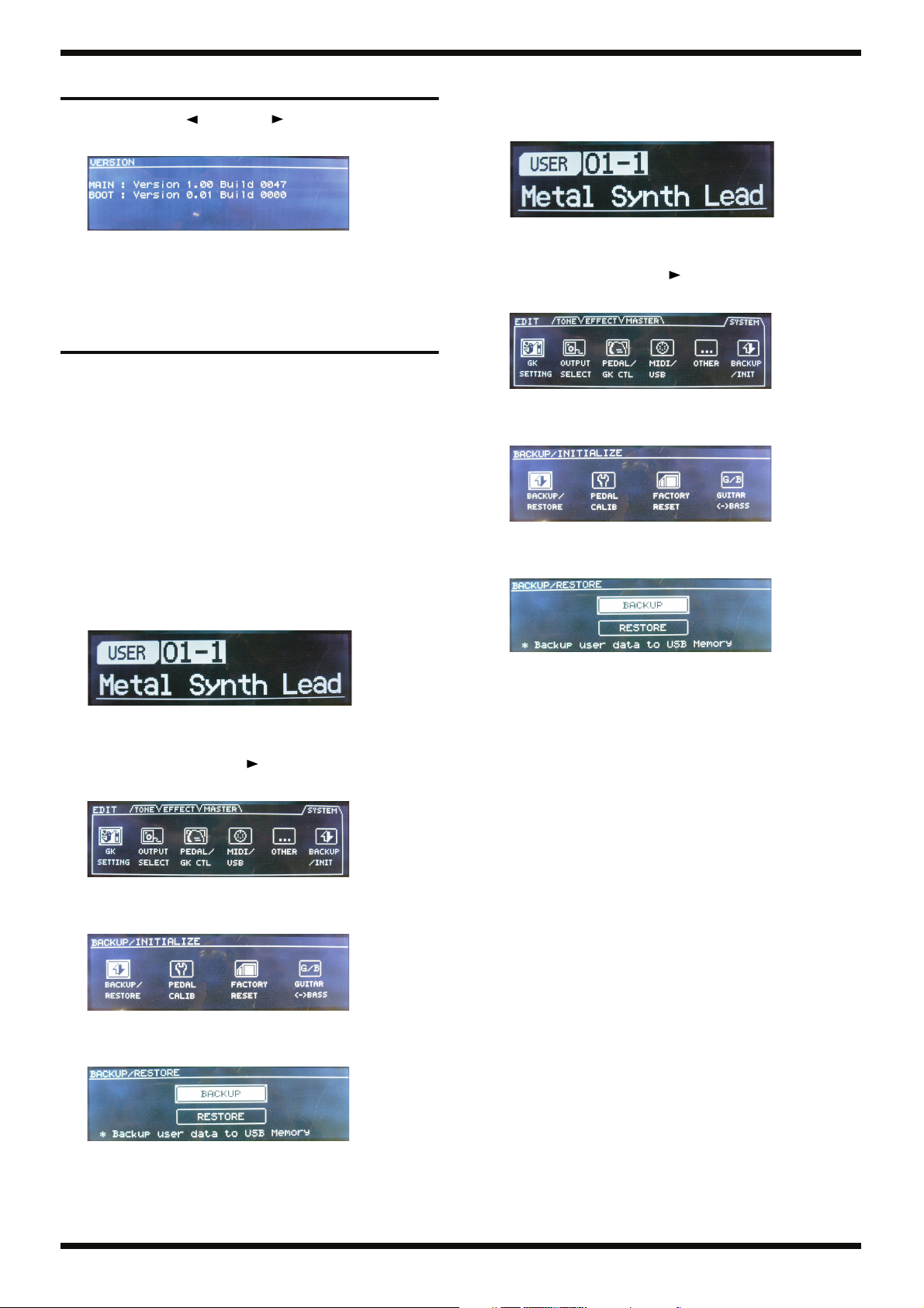
Verifying the Version
1. Hold down [PAGE ] and [PAGE ] and switch on the power.
The version information is displayed.
fig.ver-check.eps
2. Switch off the power.
Data Backup and Restore Operations
Using the method described below, you can back up all parameters, including
patch data. Note, however, that pedal sensitivity settings (calibration) cannot
be backed up. For information on adjusting the sensitivity of the pedals, refer
to Adjusting the Pedal Sensitivity (CALIB) (Owner’s Manual, p. 73).
Item Required
• USB memory device (2 MB or larger)
* Before you start, use a computer to format the device using the FAT32 file
system.
Backup Procedure
1. Switch on the power to the unit.
The initial screen appears.
fig.main.eps
Restore-operation Procedure
1. Switch on the power to the unit.
The initial screen appears.
fig.main.eps
2. Insert the USB memory device containing the backed-up user data into
the USB MEMORY connector on the side panel.
3. Press [EDIT], then press [PAGE ] 3 times.
The SYSTEM setting screen appears.
fig.edit-system.eps
4. Turn the encoder to select BACKUP/INIT, then press [ENTER].
The BACKUP/INITIALIZE screen appears.
fig.back-ini.eps
5. Select BACKUP/RESTORE, then press [ENTER].
The BACKUP/RESTORE screen appears.
fig.backup.eps
2. Insert the USB memory device into the USB MEMORY connector on the
side panel.
3. Press [EDIT], then press [PAGE ] 3 times.
The SYSTEM setting screen appears.
fig.edit-system.eps
4. Turn the encoder to select BACKUP/INIT, then press [ENTER].
The BACKUP/INITIALIZE screen appears.
fig.back-ini.eps
5. Select BACKUP/RESTORE, then press [ENTER].
The BACKUP/RESTORE screen appears.
fig.backup.eps
6. Select RESTORE, then press [ENTER].
7. At the confirmation screen, select OK, then press [ENTER].
The restore operation is executed.
8. Detach the USB memory device.
6. Select BACKUP, then press [ENTER].
7. At the confirmation screen, select OK, then press [ENTER].
The backup is executed.
8. Detach the USB memory device.
14
Loading...