


Owner’s Manual
Thank you, and congratulations on your choice of the Roland GR-33 Guitar Synthesizer.
Before using this unit, carefully read the sections entitled:
•USING THE UNIT SAFELY (page 2–3)
•IMPORTANT NOTES (page 9)
These sections provide important information concerning the proper operation of the unit.
Additionally, in order to feel assured that you have gained a good grasp of every feature provided by your new unit, Owner’s manual should be read in its entirety. The manual should be saved and kept on hand as a convenient reference.
Copyright © 2000 ROLAND CORPORATION
All rights reserved. No part of this publication may be reproduced in any form without the written permission of ROLAND CORPORATION.
USING THE UNIT SAFELY
Used for instructions intended to alert the user to the risk of death or severe injury should the unit be used improperly.
Used for instructions intended to alert the user to the risk of injury or material damage should the unit be used improperly.
* Material damage refers to damage or other adverse effects caused with respect to the home and all its furnishings, as well to domestic animals or pets.
The symbol alerts the user to important instructions or warnings.The specific meaning of the symbol is determined by the design contained within the triangle. In the case of the symbol at left, it is used for general cautions, warnings, or alerts to danger.
The  symbol alerts the user to items that must never be carried out (are forbidden). The specific thing that must not be done is indicated by the design contained within the circle. In the case of the symbol at left, it means that the unit must never be disassembled.
The ● symbol alerts the user to things that must be carried out. The specific thing that must be done is indicated by the design contained within the circle. In the case of the symbol at left, it means that the powercord plug must be unplugged from the outlet.
001
• Before using this unit, make sure to read the instructions below, and the Owner’s Manual.
..........................................................................................................
002c
• Do not open (or modify in any way) the unit or its AC adaptor.
..........................................................................................................
003
•Do not attempt to repair the unit, or replace parts within it (except when this manual provides
specific instructions directing you to do so). Refer all servicing to your retailer, the nearest Roland Service Center, or an authorized Roland distributor, as listed on the "Information" page.
..........................................................................................................
004
• Never use or store the unit in places that are:
• Subject to temperature extremes (e.g., direct sunlight in an enclosed vehicle, near a heating duct, on top of heat-generating equipment); or are
•Damp (e.g., baths, washrooms, on wet floors); or are
•Humid; or are
•Exposed to rain; or are
•Dusty; or are
•Subject to high levels of vibration.
..........................................................................................................
007
•Make sure you always have the unit placed so it is level and sure to remain stable. Never place it on
stands that could wobble, or on inclined surfaces.
..........................................................................................................
008c
•Be sure to use only the AC adaptor supplied with the unit. Also, make sure the line voltage at the
installation matches the input voltage specified on the AC adaptor’s body. Other AC adaptors may
use a different polarity, or be designed for a different voltage, so their use could result in
damage, malfunction, or electric shock.
..........................................................................................................
009
•Do not excessively twist or bend the power cord, nor place heavy objects on it. Doing so can damage the cord, producing severed elements and
short circuits. Damaged cords are fire and shock hazards!
..........................................................................................................
010
•This unit, either alone or in combination with an amplifier and headphones or speakers, may be capable of producing sound levels that could cause permanent hearing loss. Do not operate for a long period of time at a high volume level, or at a level that is uncomfortable. If you experience any hearing loss or ringing in the ears, you should
immediately stop using the unit, and consult an audiologist.
..........................................................................................................
011
•Do not allow any objects (e.g., flammable material, coins, pins); or liquids of any kind (water, soft drinks, etc.) to penetrate the unit.
..........................................................................................................
012b
•Immediately turn the power off, remove the AC adaptor from the outlet, and request servicing by your retailer, the nearest Roland Service Center, or an authorized Roland distributor, as listed on the "Information" page when:
•The AC adaptor, the power-supply cord, or the plug has been damaged; or
•Objects have fallen into, or liquid has been spilled onto the unit; or
•The unit has been exposed to rain (or otherwise has become wet); or
•The unit does not appear to operate normally or exhibits a marked change in performance.
..........................................................................................................
2
●In households with small children, an adult should provide supervision until the child is capable of following all the rules essential for the
safe operation of the unit.
..........................................................................................................
● Protect the unit from strong impact. (Do not drop it!)
..........................................................................................................
●Do not force the unit’s power-supply cord to share an outlet with an unreasonable number of other devices. Be especially careful when using extension cords—the total power used by all devices you have connected to the extension
cord’s outlet must never exceed the power rating (watts/amperes) for the extension cord. Excessive loads can cause the insulation on the cord to heat up and eventually melt through.
..........................................................................................................
●Before using the unit in a foreign country, consult with your retailer, the nearest Roland Service Center, or an authorized Roland distributor, as
listed on the "Information" page.
..........................................................................................................
●The unit and the AC adaptor should be located so their location or position does not interfere with their proper ventilation.
..........................................................................................................
● Always grasp only the plug on the AC adaptor cord when plugging into, or unplugging from, an outlet or this unit.
..........................................................................................................
● Whenever the unit is to remain unused for an extended period of time, disconnect the AC adaptor.
..........................................................................................................
●Try to prevent cords and cables from becoming entangled. Also, all cords and cables should be placed so they are out of the reach of children.
..........................................................................................................
●Never climb on top of, nor place heavy objects on the unit.
..........................................................................................................
● Never handle the AC adaptor or its plugs with
wet hands when plugging into, or unplugging from, an outlet or this unit.
..........................................................................................................
● Before moving the unit, disconnect the AC adaptor and all cords coming from external devices.
..........................................................................................................
●Before cleaning the unit, turn off the power and unplug the AC adaptor from the outlet (p. 12).
..........................................................................................................
●Whenever you suspect the possibility of lightning in your area, disconnect the AC adaptor from the
outlet.
..........................................................................................................
3

Contents |
|
Getting Started ........................................................................................ |
8 |
About the Guitar Synthesizer......................................................................................................... |
8 |
What You Can Do with the GR-33 ................................................................................................. |
8 |
IMPORTANT NOTES ............................................................................... |
9 |
Panel Descriptions................................................................................ |
10 |
Chapter 1 Producing Sounds .............................................................. |
13 |
What You Need................................................................................................................................ |
13 |
Installing the GK-2A..................................................................................................................... |
13 |
Making Connections ...................................................................................................................... |
14 |
Necessary Steps—From Powering Up to Performance............................................................ |
15 |
About Play Mode .......................................................................................................................... |
15 |
Reset to Default Factory Settings (Factory Reset) ..................................................................... |
16 |
Overall Settings for the GR-33 (SYSTEM) ................................................................................. |
17 |
Adjusting the Brightness of the Display (LCD Contrast)........................................................ |
17 |
Setting Input Sensitivity (PICKUP SENS) ................................................................................. |
17 |
Matching Pitches of Other Instruments..................................................................................... |
18 |
Adjusting the Guitar Tuning (Tuner Function) ........................................................................ |
18 |
Selecting the output device (OUTPUT SELECT)...................................................................... |
19 |
Turning off the guitar amp simulator (G.AMP SIM)............................................................... |
19 |
Playing the Internal Synth Sounds with the Guitar ................................................................ |
20 |
What To Do if There is No Sound When the Guitar is Played .............................................. |
20 |
Chapter 2 Selecting and Playing Sounds (Patches).......................... |
21 |
What Is a Patch?............................................................................................................................... |
21 |
Rewritable Patches (User Patches).............................................................................................. |
21 |
Read-only Patches (Preset Patches) ............................................................................................ |
21 |
Selecting a Patch.............................................................................................................................. |
21 |
Using the Guitar (GK-2A) to Select Patches.............................................................................. |
21 |
Using the Base Module to Select Patches .................................................................................. |
22 |
Using the Base Module plus an External Foot Switch to Select Patches............................... |
23 |
Selecting Patches with an External MIDI Foot Controller ...................................................... |
24 |
Changing the Patch Order ............................................................................................................. |
25 |
Chapter 3 Controlling Functions and Effects with the Base Module Pedals ..... |
26 |
“Pedal Effect Mode”: What It Is, and How to Call It Up......................................................... |
26 |
Getting the Same Effect While in Play Mode............................................................................ |
26 |
Turning Arpeggiator and Harmonist On/Off............................................................................ |
27 |
Changing Effects with the Pedals ................................................................................................ |
28 |
Getting a Pedal Wah Effect (Wah) .............................................................................................. |
28 |
Changing Pitch Dynamically (Pitch Glide) ............................................................................... |
28 |
Holding a Synth Tone After the String is Stopped (Hold)...................................................... |
28 |
Calling Up the Tuner Function with a Pedal............................................................................. |
29 |
4

Contents
Chapter 4 Five Basic Modes ................................................................ |
30 |
Play Mode ......................................................................................................................................... |
30 |
Pedal Effect Mode ........................................................................................................................... |
31 |
Patch Edit Mode: What It Means, How It Works...................................................................... |
32 |
System Mode.................................................................................................................................... |
33 |
Procedures in Tuner Mode ............................................................................................................ |
33 |
Getting Into and Out of Each Mode ............................................................................................ |
34 |
Chapter 5 Setting/Changing Sounds (Patches) ................................. |
35 |
Details of Putting a Patch Together............................................................................................. |
35 |
What is a “Tone”? ......................................................................................................................... |
35 |
Recording and Settings of Each Patch........................................................................................ |
35 |
Making separate settings for each string (STRING SELECT)................................................. |
35 |
The Relationship Between Arpeggiator/Harmonist and Patches ......................................... |
36 |
Saving Patches ................................................................................................................................. |
36 |
Cautions When Saving ................................................................................................................. |
36 |
Saving Patches From the GR-33 to Sequencers or Other MIDI Devices (Bulk Dump)....... |
37 |
Receiving previously saved system or patch data (Bulk Load) ............................................. |
37 |
Naming the Patches (PATCH NAME) ........................................................................................ |
38 |
Setting the Volume Level of Each Patch (PATCH LEVEL)..................................................... |
38 |
Changing the Feel of a Performance (PLAY FEEL)................................................................... |
39 |
Following the Guitar Sound Shape (Envelope Follow)........................................................... |
40 |
Increasing the Speed of Expression (Acceleration) .................................................................. |
40 |
Changing Sound Placement (PAN) ............................................................................................. |
41 |
Dividing Continuous Pitch Changes into Semitones (CHROMATIC)................................ |
42 |
When You Want to Make a Chord Resonate Beautifully........................................................ |
42 |
When You Want to Reproduce Piano-like Pitch Changes ...................................................... |
42 |
Selecting Wah Types (WAH TYPE) ............................................................................................. |
43 |
Selecting Pitch Glide Type (GLIDE TYPE)................................................................................ |
44 |
Selecting Hold Type (HOLD TYPE)............................................................................................ |
45 |
Using the CTRL Pedal .................................................................................................................... |
46 |
Using the Expression Pedal........................................................................................................... |
47 |
To Add Effects ............................................................................................................................... |
47 |
To Switch Effects (EXP PEDAL) ................................................................................................. |
47 |
Creating Synth Sounds .................................................................................................................. |
49 |
Selecting the basic ingredient (tone) of a sound (SELECT)..................................................... |
49 |
Increasing/Decreasing Attack Time (ATTACK)...................................................................... |
49 |
Changing Tone Release (RELEASE)........................................................................................... |
50 |
Changing Tone Brightness (BRIGHTNESS).............................................................................. |
50 |
Combining/Layering Two Sounds (Tones)................................................................................ |
51 |
Determining Which Tones Will Be Sounded (LAYER) ........................................................... |
51 |
Applying Detune (Subtle Pitch Shift)......................................................................................... |
51 |
Transposing by Semitones (TRANSPOSE)................................................................................ |
51 |
Determining the Volume Balance of Two Tones (1:2 BALANCE) ........................................ |
52 |
What to do When a Tone is Supposed to Sound, but Doesn’t ............................................... |
52 |
5

Contents
Chapter 6 Using the Built-in Effects.................................................... |
53 |
About the Effects Processors and Available Effects................................................................. |
53 |
Making Multi-effects Settings...................................................................................................... |
53 |
Turning multi-effects on/off (MULTI-FX SW) ......................................................................... |
53 |
Selecting a Type (MULTI-FX TYPE)........................................................................................... |
54 |
About Multi-Effects Parameters.................................................................................................. |
55 |
Making Chorus Settings ................................................................................................................ |
74 |
Making Reverb Settings ................................................................................................................ |
74 |
Temporarily Turning Off Effects (EFFECT BYPASS).............................................................. |
75 |
When the Onboard Effects Don’t Work...................................................................................... |
75 |
Chapter 7 The Arpeggiator Function .................................................. |
76 |
About the Arpeggiator Function .................................................................................................. |
76 |
About “Arpeggio Patterns” ......................................................................................................... |
76 |
Effective Use of the Hold Function During Arpeggios ........................................................... |
76 |
Changing the Sounding of Arpeggios ........................................................................................ |
77 |
Turning Arpeggiator On and Off (HAR/ARP CONTROL) ................................................... |
77 |
Selecting Tones to Be Arpeggiated (HAR/ARP SELECT)...................................................... |
78 |
Selecting Arpeggio Patterns (ARP PATTERN)......................................................................... |
79 |
Setting Tempo (ARP TEMPO)..................................................................................................... |
79 |
Using the pedal to set the tempo (Tap Tempo Teach function) ............................................. |
79 |
Chapter 8 Adding Harmonies in a Specific Key (The Harmonist) .... |
80 |
About the Harmonist...................................................................................................................... |
80 |
What You Can Do with the Harmonist ....................................................................................... |
80 |
Adding Synth Sounds to Guitar Sounds ................................................................................... |
80 |
Creating Harmonies with Two Synth Sounds .......................................................................... |
80 |
Operation .......................................................................................................................................... |
81 |
Turning the Harmonist On and Off (HAR/ARP CONTROL) ............................................... |
81 |
Selecting Harmony Tones (HAR/ARP SELECT)..................................................................... |
82 |
Setting Harmonic Intervals (HARMONY STYLE) ................................................................... |
82 |
Setting Transpose and “HARMONY STYLE” .......................................................................... |
83 |
Setting the Key (HARMONY KEY) ............................................................................................ |
84 |
Changing the Key from an External Pedal or Other Device with MIDI Note Messages (HARMONY REMOTE) ........ |
84 |
Switching Between Major and Minor During a Performance ................................................ |
85 |
Chapter 9 Connecting to External Sound Generators and Sequencers...... |
86 |
About MIDI...................................................................................................................................... |
86 |
Controlling an External MIDI Sound Device............................................................................ |
86 |
Connecting to an External MIDI Sound Device ....................................................................... |
86 |
Setting MIDI Channel/Bend Range (BASIC CHANNEL, BEND RANGE)......................... |
86 |
Changing Patch and Other Parameters by Transmitting MIDI Messages from the GR-33 (MIDI [PC]) ... |
88 |
Selecting Separate Sounds Programmed for Different Strings............................................... |
89 |
Selecting More Than 128 Tones (MIDI [CC0], MIDI [CC32]) ................................................. |
89 |
Applying the Arpeggiator or Harmonist Using an External Sound Device ........................ |
90 |
The Relationship Between Envelope Follow Function and MIDI Message ......................... |
91 |
Controlling External MIDI Devices with the Pedal ................................................................. |
91 |
6

Contents
Transposing Performance Data for an External Sound Generator (MIDI [TRANSPOSE]) |
..... 92 |
What to do if an External Module Doesn’t Produce Sound as Expected.............................. |
92 |
Using the GR-33 as an External Sequencer Input Tool ........................................................... |
93 |
Connecting to a Sequencer........................................................................................................... |
93 |
Input Procedures and Settings for Each Device ....................................................................... |
93 |
About “Local Control Off” .......................................................................................................... |
94 |
Creating Realistic Plucked String Instrument Sounds (Data) ................................................ |
94 |
Recording Arpeggiator and Harmonist Performances............................................................ |
94 |
Reducing the Size of a MIDI Pitch Bend Message.................................................................... |
95 |
Practical Use of MIDI Channels .................................................................................................. |
96 |
What to do When You Have Difficulty Sequencing ................................................................ |
96 |
Chapter 10 Other Convenient Functions ............................................ |
97 |
Re-assigning Program Change Numbers in the Order of Patches ........................................ |
97 |
Terminating Transmission of the MIDI Controller No. 7 (Volume) .................................... |
97 |
Terminating Transmission of the Bend Range Request Message......................................... |
98 |
Chapter 11 Appendices ........................................................................ |
99 |
Troubleshooting .............................................................................................................................. |
99 |
Error Messages............................................................................................................................... |
102 |
Roland Exclusive Messages......................................................................................................... |
103 |
MIDI Implementation.................................................................................................................. |
105 |
MIDI Implementation Chart....................................................................................................... |
119 |
Specifications ................................................................................................................................. |
120 |
Index..................................................................................................... |
121 |
Tone List .............................................................................................. |
122 |
Patch List............................................................................................. |
124 |
7

Getting Started
About the Guitar Synthesizer
The GR-33 guitar synthesizer, though small and compact, is big on functions and high-quality sounds.
Say “synthesizer,” and people generally think of the typical kind with a keyboard controller. However, since the keys on a keyboard synthesizer are in essence simply advanced versions of basic on/off switches, synthesizers cannot really offer a faithful expression of strings or wind instruments.
On the other hand, with the guitar, the part of the instrument that actually vibrates (i.e. the string) is touched directly. As a result it excels in the expressive power that arises from slight changes in pitch—changes even smaller than a semitone—or vibrato or muting. And because guitars are easy to play, there are more people playing guitars than keyboards.
With these points in mind, the guitar synthesizer was developed as an instrument that, while played like a guitar, could be used for sound generation much like other synthesizers.
The guitar synthesizer is set up with separate pickups for each of the guitar’s metal strings. These pickups register and send the frequency and amplitude information in each strings’s vibration to the synthesizer, which then in turn expresses the data as pitch, volume, and tone.
By connecting an external MIDI device (e.g. another sound generator) via the MIDI OUT connector, you can also export guitar performance data while simultaneously playing the instrument’s internal sound generator.
What You Can Do with the GR-33
●While enjoying the experience of playing an ordinary guitar, you can choose from a huge palette of synthesizer sounds—384 in all.
→You can take solos using synth sounds only, or layered guitar and synth sounds. You can even switch between the two modes as you play.
→When playing chords, you can enjoy the rich, full ensemble sounds that a synthesizer provides.
→You can switch from electric guitar to other instrument sounds—acoustic guitar, bass, organ, winds, ethnic instruments, and so on—in an instant, without physically changing instruments.
●When properly installed, the GK-2A divided pickup (sold separately) can also be used with an acoustic guitar strung with metal strings.
●Not only can you layer two synthesizer tones—and freely assign sounds to each string—you can also store fine adjustments to such settings as brightness and attack. You can also store differences between the pitch of the guitar and the synthesizer sounds (p. 49–52).
●With the Synth Harmonist function, you can add beautiful synthesizer harmonies—in keys you select— to guitar sounds or to synth sounds (p. 80).
●You can get various arpeggio effects with the built-in arpeggiator (p. 76).
●By applying effects (reverb, chorus and multi-effects) to a synthesizer sound, you can make it even richer and fuller (p. 53).
●You can use a variety of panning effects: use two different synth sounds in stereo, or spread out the six guitar string sounds from left to right, placing each sound in its ideal stereo location, and so on (p. 41).
●With the four tone-switching pedals, you can get various effects, such as wah-wah and whammy (p. 28– 29).
●You can use the supplied expression pedal to control various aspects of the sound, such as volume and tone, while you play (p. 47). No additional equipment is required.
●You can also convert a guitar performance into MIDI messages that allow you to play external MIDI sound generators (p. 86).
●By recording your playing into a MIDI sequencer, you can create realistic plucked stringed instrument sounds—something that keyboards just can not do as easily—adding greater expression to melody parts (p. 93).
●Tuning is a snap when you use the guitar tuner function (p. 18).
8

IMPORTANT NOTES
291a
In addition to the items listed under “USING THE UNIT SAFELY” on page 2, please read and observe the following:
Power Supply
301
●Do not use this unit on the same power circuit with any device that will generate line noise (such as an electric motor or variable lighting system).
302
●The AC adaptor will begin to generate heat after long hours of consecutive use. This is normal, and is not a cause for concern.
307
●Before connecting this unit to other devices, turn off the power to all units. This will help prevent malfunctions and/or damage to speakers or other devices.
Placement
351
●Using the unit near power amplifiers (or other equipment containing large power transformers) may induce hum. To alleviate the problem, change the orientation of this unit; or move it farther away from the source of inter-
ference.
352
●This device may interfere with radio and television reception. Do not use this device in the vicinity of such
receivers.
354a
●Do not expose the unit to direct sunlight, place it near devices that radiate heat, leave it inside an enclosed vehicle, or otherwise subject it to temperature extremes.
Excessive heat can deform or discolor the unit.
355
●To avoid possible breakdown, do not use the unit in a wet area, such as an area exposed to rain or other moisture.
Maintenance
401a
●For everyday cleaning wipe the unit with a soft, dry cloth or one that has been slightly dampened with water. To remove stubborn dirt, use a cloth impregnated with a mild, non-abrasive detergent. Afterwards, be sure to wipe
the unit thoroughly with a soft, dry cloth.
402
●Never use benzine, thinners, alcohol or solvents of any kind, to avoid the possibility of discoloration and/or deformation.
Repairs and Data
452
●Please be aware that all data contained in the unit’s memory may be lost when the unit is sent for repairs. Important data should always be backed up in another MIDI device (e.g., a sequencer), or written down on paper (when possible). During repairs, due care is taken to avoid the loss of data. However, in certain cases (such as when circuitry related to memory itself is out of order), we regret that it may not be possible to restore the data, and Roland assumes no liability concerning such loss of data.
Memory Backup
501b
●This unit contains a battery which powers the unit’s memory circuits while the main power is off. When this battery becomes weak, the message shown below will appear in the display. Once you see this message, have the battery replaced with a fresh one as soon as possible to avoid the loss of all data in memory. To have the battery replaced, consult with your retailer, the nearest Roland Service Center, or an authorized Roland distributor, as listed on the “Information” page.
“Battery Low!”
Additional Precautions
551
●Please be aware that the contents of memory can be irretrievably lost as a result of a malfunction, or the improper operation of the unit. To protect yourself against the risk of loosing important data, we recommend that you periodically save a backup copy of important data you have stored in the unit’s memory in another MIDI
device (e.g., a sequencer).
552
●Unfortunately, it may be impossible to restore the contents of data that was stored in another MIDI device (e.g., a sequencer) once it has been lost. Roland Corporation
assumes no liability concerning such loss of data.
553
●Use a reasonable amount of care when using the unit’s buttons, sliders, or other controls; and when using its jacks
and connectors. Rough handling can lead to malfunctions.
554
● Never strike or apply strong pressure to the display.
556
●When connecting / disconnecting all cables, grasp the connector itself—never pull on the cable. This way you will avoid causing shorts, or damage to the cable’s
internal elements.
558a
●To avoid disturbing your neighbors, try to keep the unit’s volume at reasonable levels. You may prefer to use headphones, so you do not need to be concerned about
those around you (especially when it is late at night).
559a
●When you need to transport the unit, package it in the box (including padding) that it came in, if possible. Otherwise,
you will need to use equivalent packaging materials.
562
●Use a cable from Roland to make the connection. If using some other make of connection cable, please note the following precautions.
Some connection cables contain resistors. Do not use cables that incorporate resistors for connecting to this unit. The use of such cables can cause the sound level to be extremely low, or impossible to hear. For information on cable specifications, contact the manufacturer of the cable.
9
Panel Descriptions
13 |
|
|
|
14 |
|
11 |
|
|
|
|
|
||
2 |
3 |
4 |
5 |
|
|
|
1 |
|
|
|
|
|
12 |
6 |
7 |
8 |
9 |
|
10 |
|
|
|
|
15 |
|
16 |
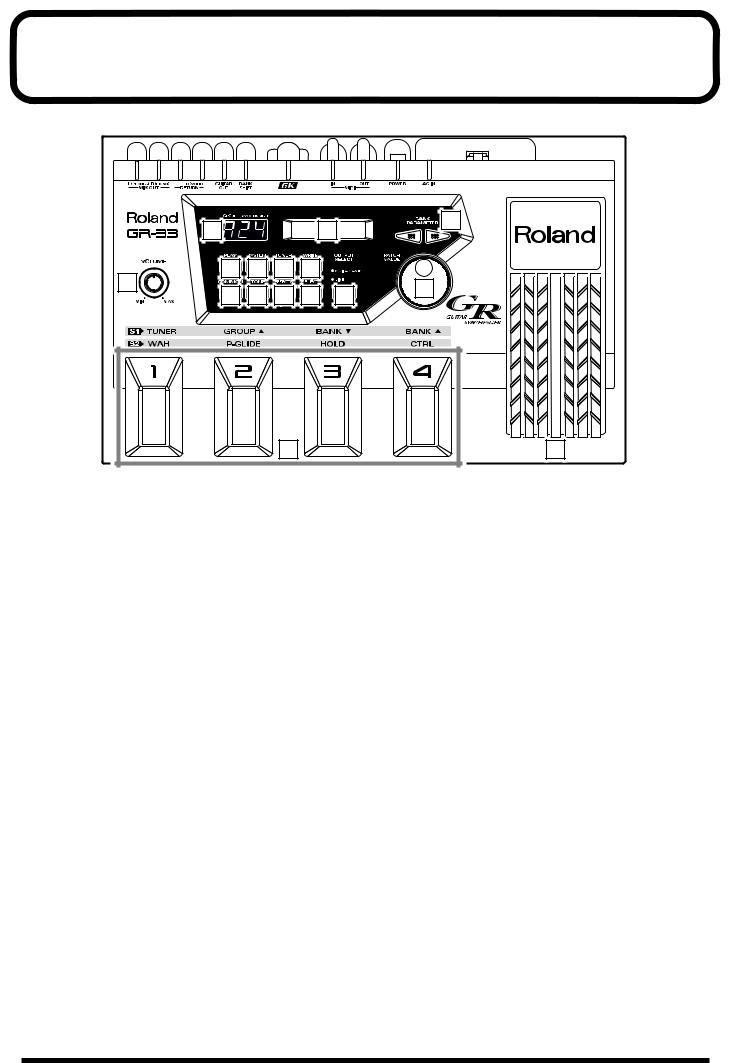
1 |
VOLUME Knob |
6 |
COMMON Button |
The VOLUME knob adjusts the signal volume output from the MIX OUT jack. The center mark provides an easy reference setting when connecting the GR-33 to an instrument amp or mixer.
*The output level from the GUITAR OUT jack is controlled separately.
2 PLAY Button
This button selects Play mode.
To play sounds, press this button to enter Play mode. (The GR-33 is in Play mode at start-up.)
3 SYSTEM Button
This button selects System mode.
Press this button to enter System mode. When you are in System mode, you can make settings to the GR-33 itself, as opposed to making settings for specific sounds.
4 TUNER Button
This button selects Tuner mode.
When you press this button, the Tuner function will be turned on, and you can tune your instrument.
5 WRITE Button
Use this button to write a patch (Patch Write).
This button also confirms the Factory Reset and Bulk Dump operations.
Press this button to access Patch Edit mode’s COMMON settings—COMMON settings apply to an entire patch, as opposed to the settings that apply to its individual tones or effects.
Press this button to enter Patch Edit mode and adjust settings such as the patch name and patch pedal functions.
7 TONE Button
Press this button to access Patch Edit mode’s TONE settings—TONE settings shape the sound of the individual tones that make up a patch.
8 EFFECTS Button
Press this button to access Patch Edit mode’s EFFECTS settings—these settings allow you to adjust the patch’s reverb, chorus, and multi-effect.
9 STRING SELECT Button
When selecting and activating the tones to be played in a patch (LAYER), and when setting transposition (TRANSPOSE) and other individual-string settings, use this knob to select the string you wish to set up.
10 OUTPUT SELECT Button
This button selects the output device connected to MIX OUT jacks.
10
Panel Descriptions
11 BANK/PARAMETER Button
Press these buttons in Play mode to switch patch banks.
In System mode and Patch Edit mode, these buttons select the parameter to be adjusted.
12 PATCH/VALUE Dial
In Play mode, turn this dial to scroll through the different patches or tones in order.
In System mode and Patch Edit mode, use this knob to adjust parameter values.
13 Three-digit Display
In Play mode, the three-digit display shows the currently selected patch’s number.
In System mode, Patch Edit mode, and Pedal Effect mode, this display shows “SYS,” “Edt,” or “PdL,” respectively, to indicate the current mode. For parameters that can be set independently for each string, the display indicates the currently selected string’s number.
14 Display
In Play mode, the main display shows the currently selected patch’s name and the current Harmonist/ Arpeggiator status.
In other modes, the display shows the value and status of the currently selected item, or “parameter.” Various messages also appear on this display.
15 Foot Pedal
These are four foot-operated switches. In Play mode, together with the GK-2A’s “S1,” they primarily switch patches. After pressing the GK-2A’s “S2” to go into Pedal Effect mode, you can step on a switch to activate performance effects such as wah, pitch glide, and hold.
16 Expression Pedal
Use this pedal to control a variety of things, including the volume, tone and pitch of the current synth sound, and the arpeggiator tempo.
● When you operate the expression pedal, please be careful not to get your fingers pinched between the movable part and the panel.
In households with small children, an adult should provide supervision until the child is capable of following all the rules essential for the safe operation of the unit.
11
Panel Descriptions
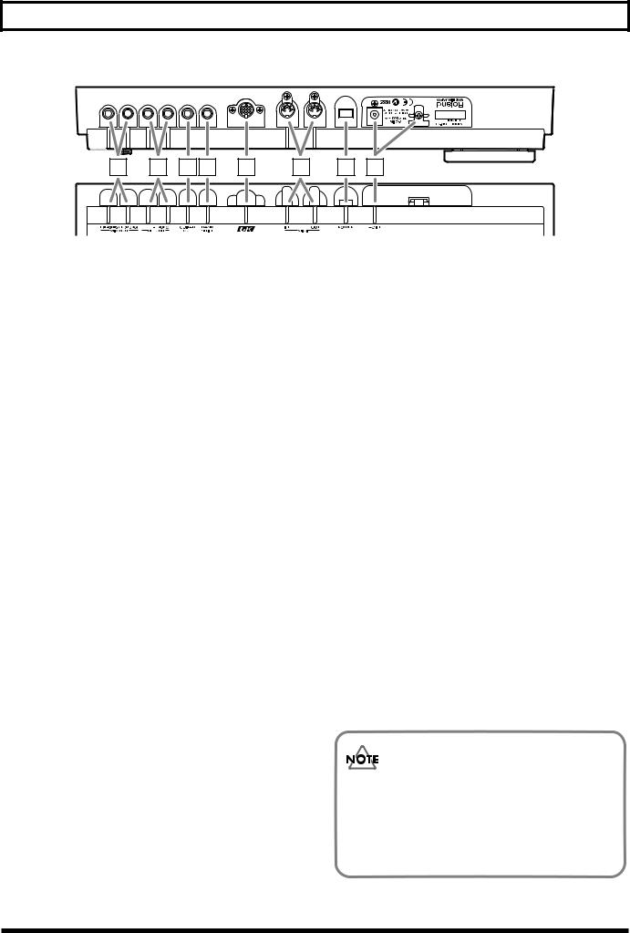
17 |
18 |
19 20 |
21 |
22 |
23 |
24 |
17 MIX OUT Jacks L(PHONES)/R(MONO) |
21 GK IN Connector |
The output of the synthesizer is sent out, or “output,” from here. Ordinarily, two cables are plugged into the L and R jacks, and the signal is then sent to a stereo amplifier.
You can use the L (PHONES) jack as a headphone jack for stereo headphones that have a standard 1/4” stereo plug—leave the R (MONO) jack unplugged.
You cannot simultaneously use the R (MONO) jack as a mono output while using the L (PHONES) jack as a headphone jack.
When there is nothing connected to the GUITAR OUT jack, the sound of the guitar itself is also mixed into these outputs.
*In order to fully experience the quality of the factory-installed patches, we recommend using a stereo amplifier or stereo headphones. When connecting the GR-33 to a mono amp, use only the R (MONO) jack.
Use this special 13-pin branch cable, included with the GR-33, to connect the GK-2A divided pickup (sold separately).
*For connection to a guitar designed for use with a synthesizer, consult the guitar’s manufacturer or your dealer.
22 MIDI Connectors (MIDI IN/OUT)
Plug MIDI cables into these jacks to connect the GR-33 to an external MIDI device. Do this when you want the GR-33 to control sounds in an external MIDI sound generator module, or to load tone data stored on an external MIDI storage device.
23 Power Switch
This is the switch that turns power to the GR-33 on and off.
18 GUITAR RETURN Jack L/R(MONO)
When using the GUITAR OUT jack (see below) as an external effect send, use this jack to return the signal. The synthesizer sound and the guitar sound with effects are output together from the MIX OUT jacks.
19 GUITAR OUT Jack
Use this jack when you want the guitar sound to be output from the GR-33 separately from the synth sound. Connect the jack to your guitar amp or guitar effects devices.
20 BANK SHIFT Jack
Use this jack for connecting a patch bank expansion foot switch to the GR-33.
You can connect two Boss FS-5U foot switches using a PCS-31 cable (each sold separately). Expansion foot switches control different functions in all modes except Play mode.
24 AC Adapter Jack/Cord Hook
Connect the AC adapter included with the GR-33 to this jack. Hang the adapter cord on the cord hook to help prevent the accidental pulling out of the cord from the jack while you are playing.
*Use ONLY the AC adapter included with this guitar synthesizer.
The explanations in this manual include illustrations that depict what should typically be shown by the display. Note, however, that your unit may incorporate a newer, enhanced version of the system (e.g., includes newer sounds), so what you actually see in the display may not always match what appears in the manual.
12
Chapter 1 Producing Sounds
What You Need
The following items are necessary for getting sounds from your GR-33:
●GR-33 base module, with included accessories (AC adapter, 13-pin cable)
●Amplifier, speakers, and cables—a completely stereophonic system is preferable—or stereo headphones
●GK-2A divided pickup
●Metal-stringed guitar with GK-2A properly installed
In addition to the above items, you should also have the following items on hand if needed:
●Guitar amplifier, guitar effects (for adding to guitar sounds)
●External bank shift switches (Boss FS-5U, optional) — to use two foot switches, a branch cable (stereo x 1 → mono x 2, 1/4” phone plugs) is required (p. 23)
●MIDI foot controller (FC-200 or similar unit, optional) (p. 24)
Installing the GK-2A
Before you can use your guitar with the GR-33, the GK-2A must first be properly installed on the guitar.
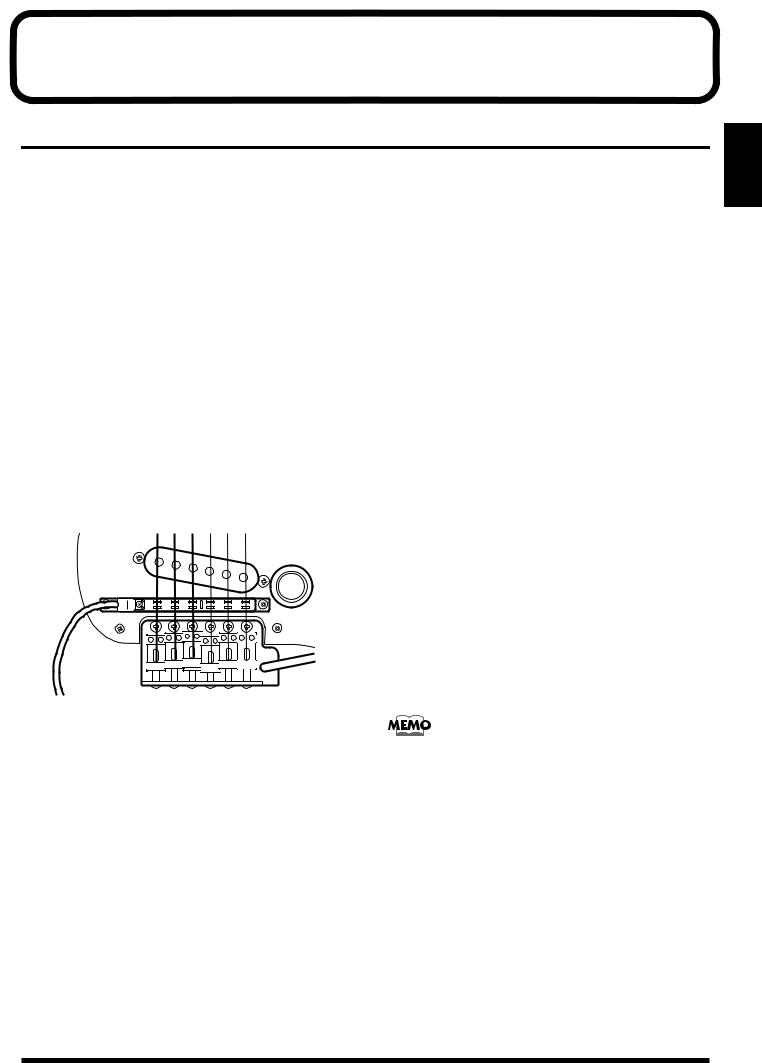
Following the procedure outlined in the GK-2A owner’s manual, attach the GK-2A’s pickup as shown in the picture.
*Be sure the Divided Pickup is correctly oriented: the cord from the Pickup should emerge from under the sixth string.
*Assembly instructions for use of the GK-2A with the other device may appear in the GK-2A owner’s manual. Installation for use with the GR-33 follows the same logic.
To confirm the quality of the GK-2A installation, please take special note of the following points:
●Make sure that the space between each string and its pickup is exactly 1 mm when you press the top fret. (Do not allow the string to get too close to the pickup.)
●Do not allow the space between the guitar bridge and the GK-2A pickups to exceed 20 mm.
●Make sure that the placement of each of the pickups’ six yokes (pole pieces) in relation to each string is correct.
For more detailed instructions, please refer to the GK-2A owner’s manual.
Guitars That Cannot Be Used with the GK-2A
While the compact design of the GK-2A allows its installation on many different guitars, please note the following types of guitars on which it cannot be used:
a.12-string, pedal steel, and other specially strung guitars; nylon-strung, gut-strung, and similar guitars; bass guitars. (The GK-2A will not operate successfully if installed on such instruments.)
b.Guitars which, due to their physical design, lack the space for proper mounting of the GK-2A.
Regarding situation “b.” above: You may be able to install the GK-2A after a minor modification of the guitar. Please consult the dealer where you purchased your GK-2A.
Some guitar manufacturers are currently shipping guitars that can be connected directly to the GR series with a 13-pin cable, without the use of a GK-2A. For more information, please ask your dealer or these guitar manufacturers.
*Take care when dealing with guitars that have more than 25 frets, or unusually high tunings, as the response around the upper frets may not be sufficient for taking full advantage of the GR-33.
1.Chap
13

Chapter 1 Producing Sounds
Making Connections
After setting up the guitar part of your system, connect your other equipment following the examples shown in the connection diagram below.
Stereo set, |
Synthesizer amp |
Guitar with GK-2A/ |
(keyboard amplifier, PA system, etc.) |
||
radio-cassette player, etc. |
|
other GR-compatible guitar |
To AUX, LINE IN
Guitar amp/
guitar effects processors
L R
L 
 R
R
See p. 15 See p. 23 |
AC adaptor |
|
|
|
(BRC series) |
Stereo headphones
The (L) MIX OUT jacks can also be used as dual stereo headphone jacks.
Also be aware that you cannot simultaneously use one jack as a LINE OUT while using the other as a headphone jack — that is, you can't use a monaural plug and a stereo plug at the same time.
*To prevent malfunction and/or damage to speakers or other devices, always turn down the volume and turn off the power on all devices before making any connections.
*Raise the volume of the amplifier only after you turn on the power to all connected devices.
*To prevent the inadvertent disruption of power to your unit— as a result of the plug being pulled out accidentally—and to avoid applying undue stress to the AC adapter jack, anchor the power cord using the cord hook as shown in the illustration.
*If you are outputting a mono signal from the GR-33, connect the cable to the R (MONO) jack of the MIX OUT jacks.
<Stereo Out>
To get the optimal performance from the GR-33, and to fully experience the quality of its patches, connect your setup to a stereo (two-channel) amplifier/speaker system, or to stereo headphones. Stereo equipment is the best way to hear the fullness of the GR-33’s sound.
14
Chapter 1 Producing Sounds
<Output>
Outputting the guitar sound and synth sound separately
You can connect a general-purpose shielded cable to the GUITAR OUT jack to add external guitar effects or to send your guitar sound to your guitar amplifier. With this arrangement, you can control the sound of the guitar exactly the same way you would if the guitar were not connected to the GR-33. The synthesizer sound — without the guitar sound mixed in—will be output from the MIX OUT jacks.
Outputting the guitar sound and synth sound together
Connect cables only to the MIX OUT jacks—do not connect a cable to the GUITAR OUT jack. The sound of the guitar itself will be output along with the synth sound from the MIX OUT jacks. This way, both guitar and synthesizer sounds can be played through a single stereo (or mono, if necessary) amp.
Applying an external effect only to the guitar sound and outputting it along with the synth sound
Necessary Steps—From Powering Up to Performance
*Once your connections have been completed (p. 14), turn on power to your various devices in the order specified. By turning on the devices in the wrong order, you risk causing malfunction and/or damage to speakers and other devices.
After you have finished checking your connections, turn the GR-33’s VOLUME knob all the way counterclockwise—thus turning its volume all the way down—and press the power switch on the rear panel to turn on the GR-33.
(Pressing the switch again turns the power off.)
If you wish, use the procedure described in “Reset to Default Factory Settings (Factory Reset)” (p. 16) to return the GR-33’s settings to their original values before beginning.
*This unit is equipped with a protection circuit. A brief interval (a few seconds) after power up is required before the unit will operate normally.
Make the following connections.
GR-33 GUITAR OUT Jack
↓
External Effect Input
External Effect Output
↓
GR-33 GUITAR RETURN Jack
The synthesizer sound and the guitar sound with effects are output together from the MIX OUT jacks.
Listening through headphones
Make sure nothing is plugged into the L (MONO) MIX OUT jack, and connect a set of stereo headphones to the R (PHONES) jack.
*You cannot simultaneously use the R (MONO) jack as a LINE OUT while using the L (PHONES) jack as a headphone jack—that is, you can’t use a monaural plug and a stereo plug at the same time.
For settings appropriate to your output device, refer to “Specifying the output device (OUTPUT SELECT)” (p. 19).
About Play Mode
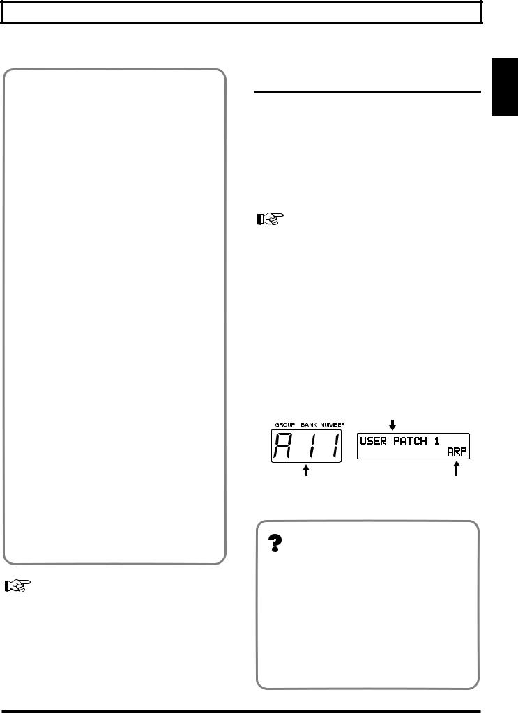
After turning on the GR-33, confirm that “A11” appears in the three-digit display window. This is the number of the currently selected patch. Each patch contains a pair of tones that can you can switch with a pedal, etc. during performance. (→ For details, see p. 21.)
Patch Name
Currently Selected Patch |
Harmonist (HAR) |
(A11) |
or |
|
Arpeggiator (ARP) |
<About Play Mode>
When a patch number—such as the “A11” that appears right after the power is turned on—is shown in the display, you are in Play mode. You will typically be in Play mode as you perform. Play mode is the basic state of the GR-33.
Until you are familiar with how everything in the GR-33 works, remember this: You can always return to Play mode by turning the power off and then on again.
(For more about how the dials and buttons work in Play mode, please see p. 30.)
1.Chap
15
Chapter 1 Producing Sounds
Reset to Default Factory Settings (Factory Reset)
<About Factory Reset>
The procedure for restoring the GR-33’s internal settings to the state they were in when the unit left the factory is called a “Factory Reset.”
At the time of purchase, the GR-33’s user patches (A11 to D84) are the same as preset patches E11 to H84. These patches, as well as the GR-33’s system settings— including pickup sensitivity and the MIDI channels used for sending and receiving MIDI data—can be returned to their original factory-fresh state.
The Factory Reset operation undoes any settings you have changed and discards any edits you have made to its patches. If you have settings or patches you wish to preserve, use the Bulk Dump operation (p. 37) to save them to an external MIDI device, such as a sequencer, before performing the Factory Reset operation.
■ Performing a Factory Reset
1.Press [SYSTEM] to enter System mode.
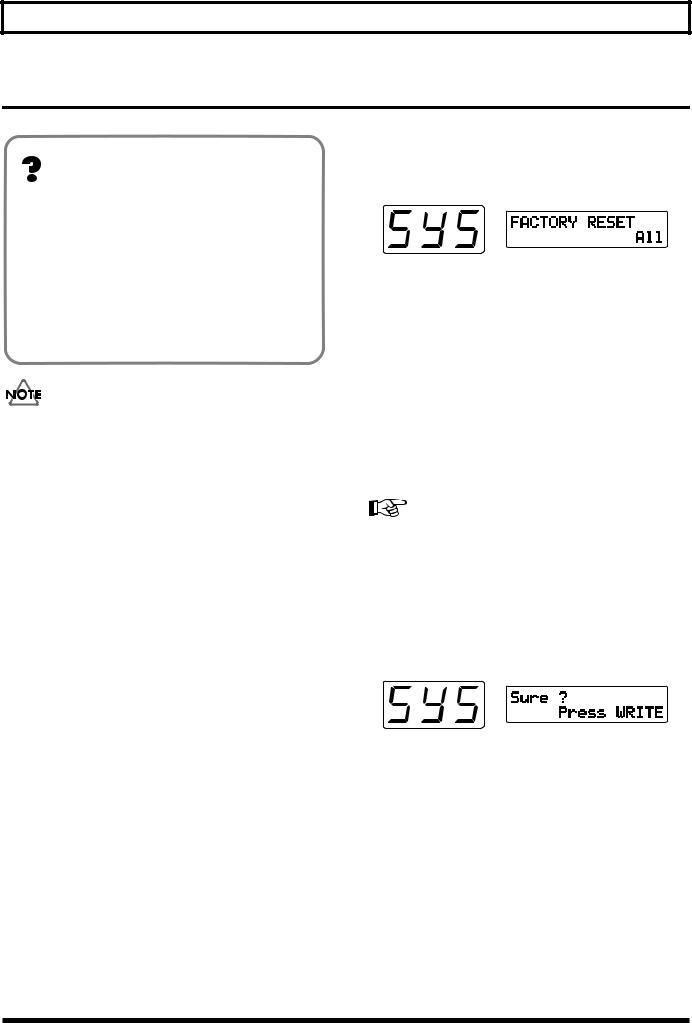
2.Press [PARAMETER] to select “FACTORY RESET.”
3.Turn [VALUE] to select the parameter—or group of parameters—you wish to reset.
•All:
Restores all settings to their original state.
• System:
The System settings will be restored to their factory settings.
• User Patch:
Patch settings will be restored to their original state.
• PC Number:
Program Change numbers are re-assigned according to the current order of the patches.
For more detailed information about the “PC Number,” refer to “Re-assigning Program Change Numbers in the Order of Patches” (p. 97).
4.When you have selected the desired parameters, press [WRITE].
The message “Sure ?” appears, asking you to confirm that you want to go ahead and perform the Factory Reset operation.
5.To execute the operation, press [WRITE] again.
“Now Writing...” appears in the display. In a moment, the GR-33 automatically returns to Play mode, completing the factory Reset.
To cancel the operation, press [PLAY].
*This means that the processing of data is in progress. Once you press [WRITE], be sure not to turn off the power until to return to Play mode.
16
Chapter 1 Producing Sounds
Overall Settings for the GR-33 (SYSTEM)
Adjusting the Brightness of the
Display (LCD Contrast)
■ Adjusting the Brightness of the Display
1.Press [SYSTEM] to enter System mode.
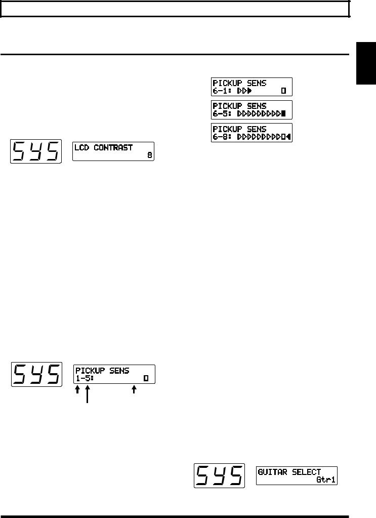
2.Press [PARAMETER] to select “LCD CONTRAST.”
3.Turn [VALUE] to adjust the contrast.
4.When you have finished adjusting the display, press [PLAY] to return to Play mode.
Sensitivity: lo
Sensitivity: hi
If the indicator furthest to the left is lit, the level is set too high, so turn [VALUE] to lower the sensitivity.
*If the sensitivity is set too high, there may be dropouts in the sound, or the response to dynamic changes in your playing may be reduced. Setting sensitivity too low may also result in problems, so make this adjustment carefully.
5. Adjust Strings 5 to 1 using the same technique.
Setting Input Sensitivity (PICKUP
SENS)
With the power turned on, adjust the input sensitivity of each string according to how the GK-2A is mounted and to match your own picking strength. Since these settings are stored automatically—and will not be lost even if the power is turned off—it is not necessary to reset the sensitivity each time you play.
■ Procedure for Setting Input Sensitivity
1.Press [SYSTEM] to enter System mode.
2.Press [PARAMETER] to select “PICKUP SENS.”
Sensitivity-setting is activated, and the following appears in the display window:
String Number |
Level Meter |
Input Sensitivity
3.When String 6 of the guitar is played, the string number in the display automatically switches to “6.”
The level meter shown in the display will light from the left, showing how strongly the string is played. The current input-sensitivity setting for the string will also be displayed next to the string number.
4.Use [VALUE] to adjust the sensitivity so that the square indicator lights when you play most strongly in actual performance.
6.When you have finished, press [PLAY] to return to Play mode.
In any of the following situations, please be sure to readjust the sensitivity settings!
•When using a guitar for which you have not yet made sensitivity adjustments
•After performing a Factory Reset (p. 16)
•When you change the mounting of the GK-2A to accommodate a change in the guitar, such as when string height has been readjusted
•When you replace a string with one of a different gauge
In some rare cases, the sensitivity meter may show too high a reading even with sensitivity at its lowest setting. If this does occur, widen the space slightly between the GK-2A’s separate pickups and the strings.
Using Multiple Guitars (GUITAR SELECT)
You can store four separate string-sensitivity setups that can be called up to match any of four guitars you are currently using.
■ Calling Up the Different Sensitivity Settings
1.Press [SYSTEM] to enter System mode.
2.Press [PARAMETER] to select “GUITAR SELECT.”
1.Chap
17
Chapter 1 Producing Sounds
3.Turn [VALUE] to select Gtr1–Gtr4.
The setting you select will be loaded.
*With the factory settings, this is set to “Gtr1.”
If you wish to create a new input-sensitivity setup, press [PARAMETER] to select “PICKUP SENS,” and then adjust the sensitivity settings for the current guitar’s six strings.
4.After setting each string’s sensitivity, press [PLAY] to return to Play mode.
Create four different input-sensitivity setups for Gtr1– Gtr4 to store the sensitivity settings for four different guitars.
* The last-selected sensitivity setup is the one currently in effect.
Matching Pitches of Other
Instruments
The master tuning (basic pitch) set at the factory for the GR33’s sounds and internal tuner is A = 440.0 Hz.
If you need to match the GR-33’s tuning to the tuning of another instrument—or if you want to change the master tuning for any other reason—perform the following steps.
■ Changing the Master Tune Setting
1.Press [SYSTEM] to enter System mode.
2.Press [PARAMETER] to select “MASTER TUNE.”
3.Turn [VALUE] to select the desired pitch. The pitch can be changed to any frequency from 427.4 to 452.6 Hz.
4.Press [PLAY] to return to Play mode.
*The pitch of the synthesizer sound does not change when you change the GR-33’s Master Tune setting—the synth sound continues to follow the tuning of the guitar. Therefore, after adjusting the master tuning, you should use the Tuner function to re-tune your guitar to the new basic pitch, and the pitch of the synth sounds will play in the new tuning.
Adjusting the Guitar Tuning
(Tuner Function)
To accurately set a guitar’s pitch, use the GR-33’s built-in tuner to tune the guitar. This tuner works exactly the same way other tuners on the market do.
■ Tuning the Guitar
1.While pressing [S1] on the GK-2A, step on the first foot pedal—[1] (TUNER) —or press [TUNER].
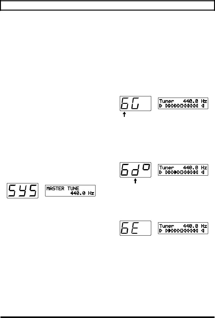
The Tuner function is called up, and the following appears in the display.
String Numbers 1 to 6
2.Play String 6 on the guitar.
The string number automatically switches to “6.”
The note to which String 6 is currently tuned—notes are tuned by semitones—is shown in the second position on the display. (“D#” in the figure shown below.)
Pitch name
(“D#” – The marking in the third place denotes sharp)
3.Turn the string’s tuning peg while playing String 6 until the screen shows the name of the note to which you want to tune the string.
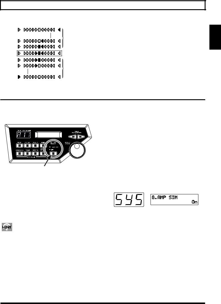
4.Make fine adjustments to the string’s tuning peg until the mark illuminated in the display moves to the center position and both side.
When the center indicator lights, String 6 is tuned precisely to “E.”
18
Chapter 1 Producing Sounds
too high
Just Tuned
too low
5.Tune each of the other strings, 5 to 1, to A, D, G, B, and E, respectively.
6.When you are finished tuning, press any foot pedal, [S1] or [S2] on the GK-2A, or [PLAY], to return to Play mode.
1.Chap
Selecting the output device (OUTPUT SELECT)
In order for the GR-33 to produce the correct output levels, you must select the type of device to which its outputs are connected (MIX OUT).
1.Press [OUTPUT SELECT] and select the appropriate setting.
The currently selected setting will light.
•GUITAR AMP:
Select this when using a dedicated guitar amp.
• LINE:
Select this when using a keyboard amp, general-purpose instrument amp, mixer, MTR, or headphones.
The GR-33’s sound generator is a PCM synthesizer that can reproduce a wide range of timbres. To optimally capture its rich synthesizer sounds, use a keyboard amp, other general instrument amplifier, PA system, or other such equipment instead of a guitar amplifier if possible.
*Changing the OUTPUT SELECT setting will not affect the settings that are stored in each patch.
Turning off the guitar amp simulator (G.AMP SIM)
The GR-33 has a built-in guitar amp simulator (G.AMP SIM). If OUTPUT SELECT is set to “LINE,” the guitar amp simulator will be applied only to the guitar sound itself. This allows you to create the illusion of the original guitar sound being played through a guitar amp, even when it is being fed directly into another device.
If you are not using the GR-33’s internal guitar amp simulator—if you are using an external amp simulator effect device, for example—set the GR-33 as follows.
■ Turning the Amp Simulator Off
1.Press [SYSTEM] to enter System mode.
2.Press [PARAMETER] to select “G.AMP SIM”
3.Turn [VALUE] to select “Off.”
•Off:
The amp simulator will not be used.
• On:
The amp simulator will be used when OUTPUT SELECT is set to “LINE.”
4. Press [PLAY] to return to Play mode.
*When you once again wish to use the amp simulator, select “On” in Step 3.
19
Chapter 1 Producing Sounds
Playing the Internal Synth Sounds with the Guitar
After checking the connections to the amplifier you are using, completing the sensitivity setup and tuning your guitar, try playing some sounds.
■How to Play the GR-33’s Sounds with the Guitar
1.Make sure that the display indicates Play mode (p. 15).
2.Set the GK-2A’s selector switch to “SYNTH.”
3.Turn SYNTH VOL on the GK-2A counterclockwise to raise the volume to a suitable level.
4.Set the VOLUME knob on the GR-33 to its center position.
5.When you press Pedal 3, the number in the display changes to “A13,” and the corresponding patch (sound) is selected.
You are now ready to play. Play your guitar while gradually turning up the volume on your amplifier, and you will hear the selected patch—patch A13—from the GR-33’s internal sound generator.
To Hear the Normal Guitar Sound...
Set the GK-2A’s selector switch to “MIX.” If you then switch to “GUITAR,” the synthesizer sound generator will be muted, and only the sound of the guitar will remain.
To Change the Volume of the Synth Sound Generator...
Adjust the volume using either the SYNTH VOL knob on the GK-2A or the GR-33’s VOLUME knob.
Turning the GR-33’s VOLUME knob changes the overall volume output from the MIX OUT jacks. Thus, when the guitar sound is included in the MIX OUT signal, both guitar and synthesizer sound levels are changed. (The guitar sound output from the GUITAR OUT jack is not affected. The guitar volume is also unchanged when you use the GK-2A’s SYNTH VOL knob.)
What To Do if There is No Sound When the Guitar is Played
First, check the following:
•Check to see that amplifier and other equipment volume levels are correct, and confirm that all the equipment is properly connected (p. 14).
•Make sure the volume on both the GR-33 and the GK-2A are up. Also, make sure that the guitar/synth switch is not set to GUITAR.
When the Sound of a Specified Patch Fails to Play on All the Strings (or on a Particular String)
•Try pressing the expression pedal (p. 11) as far down as it will go.
•When using a monaural connection to your amp, be sure to connect your cable to the R (MONO) jack of the GR-33 MIX OUT jacks.
•Confirm that the synth sounds have not been muted for any strings in the TONE “LAYER” parameter in Patch Edit mode (p. 51).
If the volume levels of the strings vary widely, please recheck your input sensitivity (PICKUP SENS) settings (p. 17).
20
Chapter 2 Selecting and Playing Sounds (Patches)
What Is a Patch?
“Patch” is the term for the GR-33’s tones that can be called up at any time with a foot switch or other device. There are 256 patches stored in the GR-33. As an example, the “A11” that appears in the display when the power is switched on indicates that patch number A11 has been called up, and that the unit is ready to be played.
This unit’s basic unit of sound is the “tone.” Tones consist of sound waveforms, such as “GR Piano,” “Pipe Organ,” and “Nylon Gtr mp” A total of 384 such tones are provided onboard. (How to choose tones → p. 49; list of tones → p. 122)
In any patch, up to two selected tones are combined, and then various settings and adjustments, such as brightness, attack, difference between synthesizer and guitar pitch, and the like are made. The user has full freedom to make these settings and adjustments so that the patch may best suit the song to be played.
Another result of changing these settings is that you can write and store 128 patches (in the first half of the patch bank). (For more detailed information about patches, please refer to p. 35.)
Patch numbers are indicated by a three-digit code: “a letter of the alphabet A–H (Group),” followed by “a numeral 1 to 8 (Bank),” and then “a numeral 1 to 4 (number on the pedal).”
(Example: A83, d24, F61, etc.)
Rewritable Patches (User Patches)
Patches in Groups A through d
(A11 to A84, b11 to b84, C11 to C84, and d11 to d84)
Here you can create patches to fit a song, or for other purposes, and then store those patches in memory.
(When you purchased your GR-33, the patches stored in these groups were the same as the following preset patches. If you want to reset the GR-33 patches to the original conditions, please carry out the Factory Reset operation explained on p. 16.)
Read-only Patches (Preset Patches)
Patches in Groups E through H
(E11 to E84, F11 to F84, G11 to G84, and H11 to H84)
This is a collection of 128 preset patches, which have already been completely prepared by Roland. These patches are read-only, so although they can be changed, they cannot be written over with another patch. However, this also means no worries that they might be erased accidentally.
Preset patches are called up and used in the manner as user patches. Furthermore, they are convenient as references and basic material for the user wishing to create original patches.
2.Chap
 Numerals 1 to 4 (Pedal Numbers)
Numerals 1 to 8 (Banks)
Letters A, b, C, d, E, F, G, H (Groups)
Consecutive numerals 001 to 256 can also be substituted (p. 24).
Selecting a Patch
Using the Guitar (GK-2A) to Select Patches
Sometimes (such as when you want to listen to all of the patches one after the order) you will want to select patches using only the guitar (GK-2A). In such cases, follow the steps below. (It is unnecessary to touch any pedal or anything else on the base module.)
■ How to Select a Patch Using the Guitar
1.Press [SYSTEM] to enter System mode.
2.Press [PARAMETER] to select “S1/S2 FUNCTION.”
21
Chapter 2 Selecting and Playing Sounds (Patches)
3.Use [VALUE] to select “Patch Select.”
•Patch Select:
You can continuously switch patches with [S1] and [S2] on the GK-2A.
•Normal:
Normal status. You cannot switch patches on the GK-2A.
4.Press [PLAY] to return to Play mode.
5.Pressing the GK-2A [UP/S2] once brings you to the next higher patch; by holding the switch down, you can switch continuously. Furthermore, when the other button (here the [DOWN/S1] button) is then also pressed, the switching occurs even faster. Pressing the [S1] and [S2] buttons in the reverse fashion will similarly return you to previous patches.
S1 
(Patch Number Down)
S2
(Patch Number Up)
Now, using the GK-2A buttons to switch patches, try playing the guitar to listen to the patches in sequence.
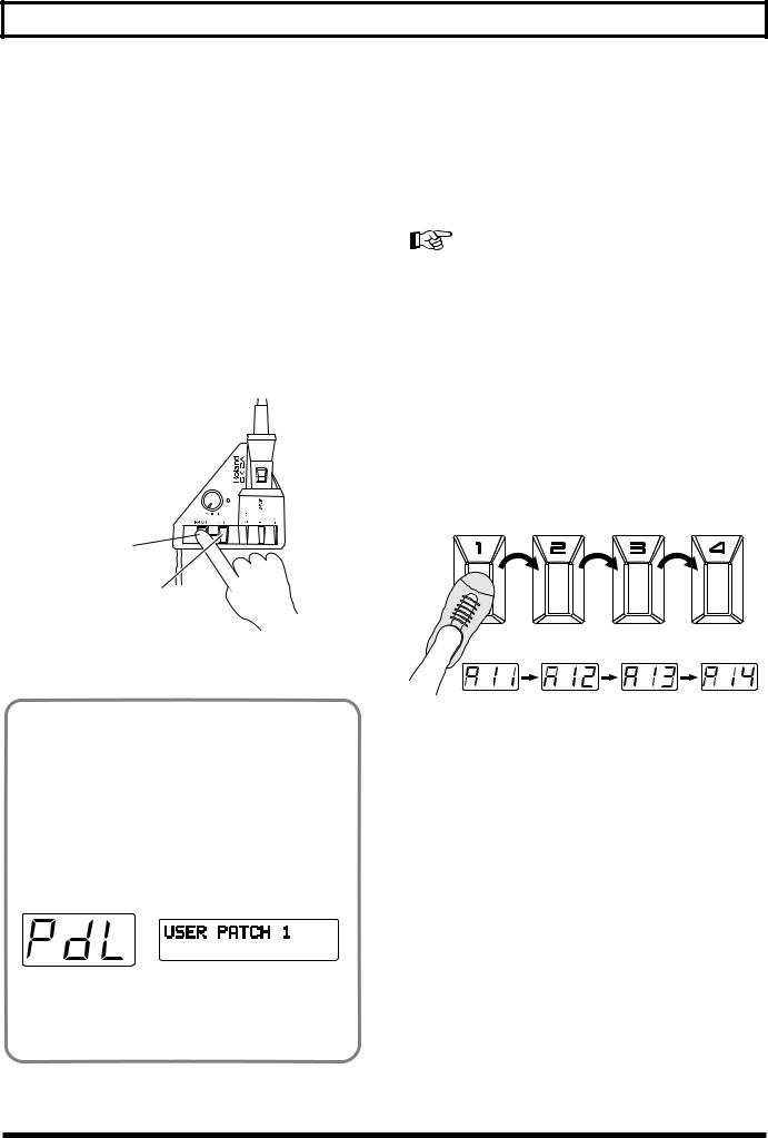
<Using the Pedal>
With the GR-33 in the state just described, you can get various pedal effects (explained later). For example hold, pitch glide, and the like can be obtained, by stepping on the base unit’s four pedals. (For details, see p. 28.) To indicate this status, when “S1/S2 FUNCTION” is selected in “Patch Select,” the “PdL” display appears (approximately once every four seconds) in the threedigit display, showing the patches and their corresponding numbers.
fig.2-04
Additionally, with the unit in this status, an external bank shift pedal can be used to change patch numbers, both up and down, just like the [S1] and [S2] buttons on the GK-2A.
Using the Base Module to Select Patches
Selecting Patches Using the Pedal
You can select patches using the pedal only when “S1/S2 FUNCTION” is set to “Normal.”
For the “S1/S2 FUNCTION” settings, refer to p. 21.
To Use the Pedal for Calling Up Patches from the Same Group or Bank
When playing live or in the studio, by using the pedal on the base module, you can instantly select one of four patches from the same group or bank.
1.Make sure that you are in the Play mode.
If you are not in the Play mode, press [PLAY].
2.When you press pedals 1 to 4, you can instantly select a patch from the same bank of four patches in a group, with the number at the right in the display changing to show the number of the pedal currently pressed.
To Use the Pedal for Calling Up Patches from a Different Group or Bank
Used together with the GK-2A’s [S1] button, you can use the pedal function to switch patches.
1.Make sure that you are in the Play mode.
If you are not in the Play mode, press [PLAY].
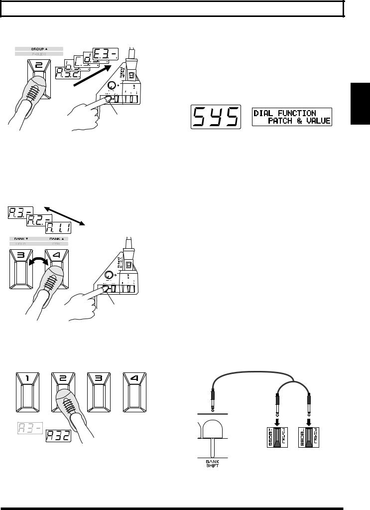
2.While pressing [S1] on the GK-2A, step on [GROUP ]
(pedal 2).
Pedal 2 continues switching to the next group only while [S1] is being held; pressing the pedal allows you to progress to the next group.
*If you wish to change only the bank without changing the group, omit step 2, and proceed to step 3.
22
Chapter 2 Selecting and Playing Sounds (Patches)
Selecting with the Dial
If you wish to use the dial to select patches, you must make the following setting for the dial.
1. Press [SYSTEM] to enter System mode.
2. Press [PARAMETER] to select “DIAL FUNCTION.”
While holding down S1
3.While pressing [S1] on the GK-2A, step on [BANK ▲] (pedal 4) or [BANK ▼] (pedal 3).
As long as the [S1] button is held down, pedal 4 works as a [BANK ▲] (BANK UP), and pedal 3 as a [BANK ▼] (BANK DOWN). The display starts to flash, and when you step on pedal 3 or 4, numbers for the bank digit (the middle number in the display) go down or up.
While holding down S1
4.After selecting the desired group/bank, release [S1], then step on the pedals.
When you press a pedal, the patch will be finalized, and the sound will change.
3.Use [VALUE] to select “PATCH&VALUE.”
•PATCH&VALUE:
The dial can be used both for selecting the patch number and for modifying values while editing.
•VALUE Only:
The dial can be used only for modifying values while editing.
4.After making the setting, press [PLAY] to return to Play mode.
In Play mode, you can rotate the [VALUE] dial to select all 256 patches A11–H84.
You can also use [BANK/PARAMETER] to move forward/backward through the banks.
Using the Base Module plus an External Foot Switch to Select Patches
By plugging a foot switch into the BANK SHIFT jack on the rear panel, you can switch banks without pressing [S1] on the GK-2A.
With one DP-5 (sold separately) to rise through patch bank numbers, or with two Boss FS-5U foot switches and a branch cable (sold separately) to move both up and down through the patch banks, it’s possible to perform this procedure using only your feet.
PCS-31
Red |
White |
2.Chap
BANK BANK DOWN UP
23
Chapter 2 Selecting and Playing Sounds (Patches)
*Sometimes when pressing and releasing the foot switch to switch banks, you may find that while the bank does change, the patch number may not (light will flash); however, this does not indicate any malfunction. You can also make the setting with the FS-5U polarity switch, as shown in the figure below.
Polarity switch
*If the “S1/S2 FUNCTION” has been set to “Patch Select,” the action of the foot switch just described changes to switching patches up and down (p. 21).
Selecting Patches with an External MIDI Foot Controller
While the base module’s four pedals are being used as designated pedals (p. 26) for such effects as hold and wah, you may also wish to switch patches using your foot.
In such cases, you should hook up an external MIDI foot controller (e.g. FC-200, Boss FC-50, and so on).
Make the settings, using the following procedure.
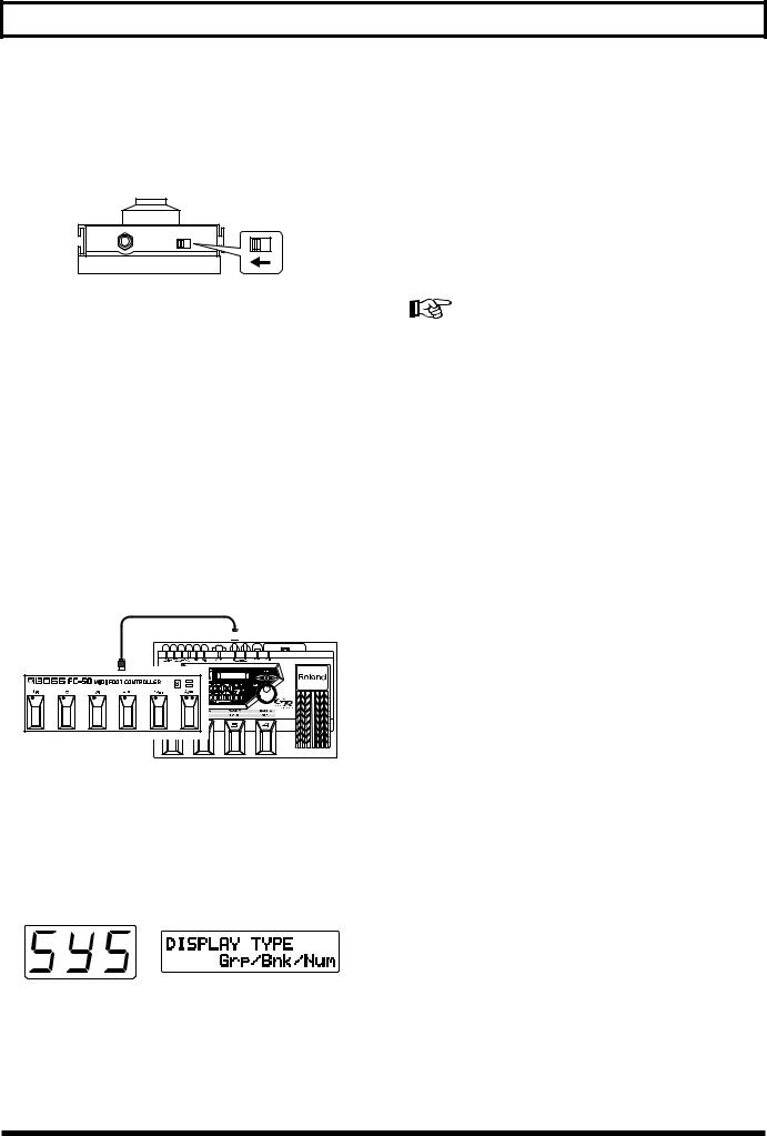
1. Connect equipment as shown in the figure below.
MIDI IN 
MIDI OUT
MIDI Foot Controller
2.Press [SYSTEM] to enter System mode.
The patch number display corresponds to the display on the MIDI foot controller, but with numbers 001 to 256 instead of the alphanumeric symbols in patch numbers used by the GR-33.
3.Press [PARAMETER] to select “DISPLAY TYPE.”
4.Use [VALUE] to select “Decimal.”
•Decimal:
Patch numbers will be displayed as a decimal number in the range of 001–256.
•Grp/Bnk/Num:
Patch numbers will be displayed as a group/bank/ number from A11–H84.
5.Press [PARAMETER] to select “S1/S2 FUNCTION.”
6.Use [VALUE] to select “Patch Select.”
For details, refer to “Selecting a Patch/Using the Guitar (GK2A) to Select Patches.”
7.Press [PLAY] to return to Play mode.
The patch number displayed will be “001,” rather than “A11.”
8.Set the MIDI send channel of the MIDI foot controller to match the channel of the GR-33 (p. 86; the factory setting is channel Mono 11).
9.Use the MIDI foot controller to switch patches externally, operating the controller according to the instructions in the owner’s manual.
*The patch number using the numeral-only format that was set in step 4 is stored in memory even after the power is turned off. If necessary, return the patch number display to the Group/bank/number format.
Additionally, user patches (001 to 128, or A11 to D84) can usually be selected when MIDI program change data is sent from the MIDI foot controller immediately after the power is turned on.
*MIDI program change numbers received by the GR-33 have a fixed one-to-one correspondence with the patches (001 to 128, or A11 to D84) they represent; this cannot be changed. (On the other hand, when patches are selected using the GR-33,
you have the freedom to change and save the MIDI program change numbers that send the data to outside equipment. → p.
88)
24
Chapter 2 Selecting and Playing Sounds (Patches)
Changing the Patch Order
When sequencing patches while performing a piece, or while you are on stage, if the patches are from the same group/ bank (for example A11 to A14), you can switch patches very smoothly by using the pedals on the base module.
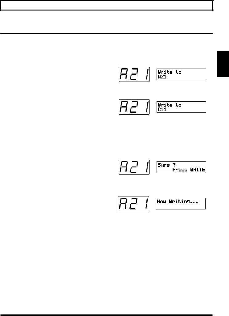
To change the order of the patches, perform the patch write (p. 36) operation. This designates the patch number (address) where the patch data from the present selection (or change) will be written.
Example: To change the contents of A21 and B62
First, to prevent the contents of patch A21 from being lost, clear a patch number that is not being used. (Since groups A through d of user patches are the same as groups E through H of preset patches, you may erase them without worry.) After that, by writing B62 → A21, then temporary placeholder → B62, the order of A21 and B62 can be swapped.
1.Select the “A21” patch.
2.Press [WRITE].
You enter Write mode, and the screen like the one below appears.
3. Use [VALUE] to select the patch you want to write to.
In this example, we will use “C11” as the writing destination patch.
4.After you have specified the writing destination patch, press [WRITE].
The following display will appear, asking you to confirm the operation.
2.Chap
5.After making sure that you want to execute this operation, press [WRITE] once again.
“Now Writing...” appears in the display, the unit automatically returns to the Play mode, completing the writing procedure.
6.Using steps 1 to 5 above, write B62 → A21 just as you did A21 → temporary place-holder (C11).
7.Complete the rearrangement by using the same process to write the temporary place-holder (C11) → B62.
*Since patch groups E through H are read-only, you cannot rearrange their order or create temporary place-holders with them. (However, you can copy them for reference or to use them as starting material when writing new patches.)
25
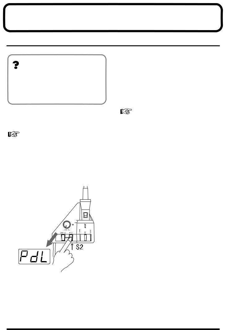
Chapter 3 Controlling Functions and Effects with the Base Module Pedals
“Pedal Effect Mode”: What It Is, and How to Call It Up
About Pedal Effect Mode
By using the four pedals on the GR-33, you can turn on and off the Arpeggiator (and Harmonist) function, and get effects such as synth sound hold and wah pedal.
This is called “Pedal Effect mode,” and along with the Play mode, is often used in performance.
■ How to Switch to Pedal Effect Mode
1.Press [SYSTEM] to enter System mode, and set the “S1/ S2 FUNCTION” to “Normal.”
For more detailed information and instructions for this procedure, refer to “Selecting a Patch/Using the Guitar (GK2A) to Select Patches” (p. 21).
2.Press [PLAY] to return to Play mode.
3.Press [S2] on the GK-2A once.
As you enter Pedal Effect mode, “PdL” (Pedal) will start to blink in the GR-33’s three-digit display.
Getting the Same Effect While in
Play Mode
If you have set “S1/S2 FUNCTION” in System mode to “Patch Select” in order to use the buttons of the GK-2A for selecting patches, you can use pedal effects in Play mode. The four pedals will act as they do in Pedal Effect mode instead of selecting patches as they normally would in Play mode. (“PdL” will appear once every four seconds or so in the 3-digit display, indicating that pedal effects are available.)
For more detailed information and instructions about this type of setup, refer to “Selecting a Patch/Using the Guitar (GK-2A) to Select Patches” (p. 21).
*With the exception of the arpeggio latch hold (p. 76), pressing more than one pedal at the same time can result in unexpected behavior, so please exercise due caution.
Press either [S1] or [S2] on the GK-2A to return to Play mode.
The same pedal can produce different effect amounts from patch to patch. These can be changed to suit a song—or for any other purpose—and can be saved as part of the patch.
For more information about each pedal effect function, and to learn how to change the effect amount, please see Chapter 5 (p. 35–52).
26
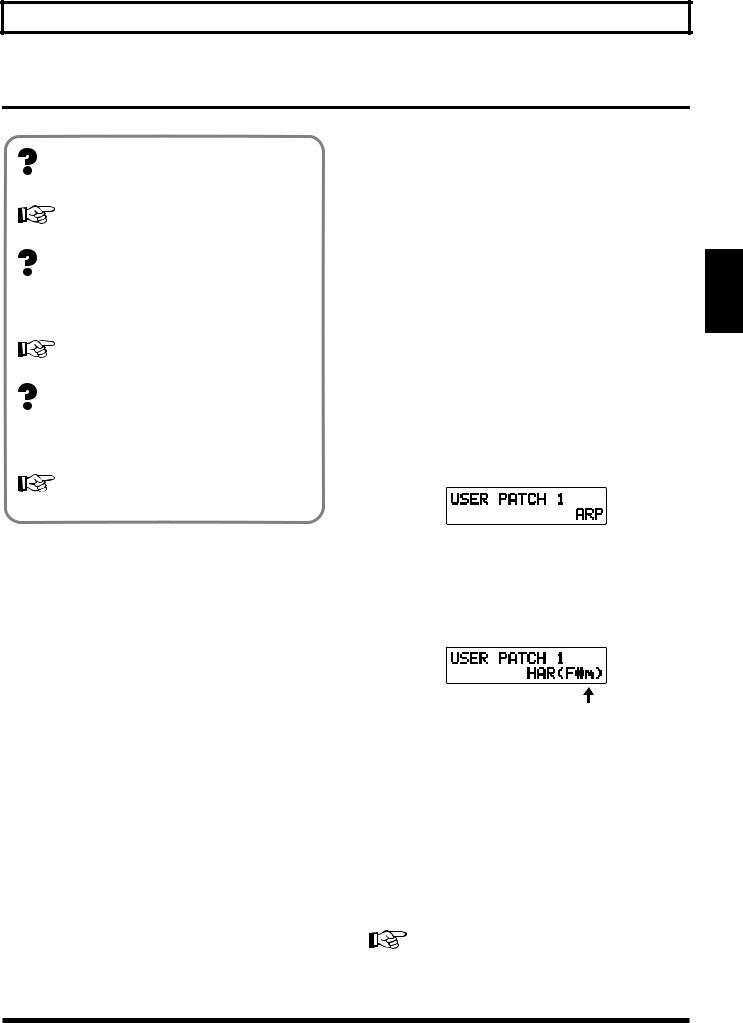
Chapter 3 Controlling Functions and Effects with the Base Module Pedals
Turning Arpeggiator and Harmonist On/Off
About MULTI-FX
These are effects for the synthesizer sound.
For details, refer to p. 53.
About Arpeggiator
This is a function that automatically creates arpeggios — chords whose notes are played in sequence, rather than simultaneously — when a chord is played.
For details, refer to p. 76.
About Harmonist
This creates harmonies in designated keys using either guitar and synthesizer sounds, or two synthesizer sounds together.
■ Using the pedals for on/off switching
1.Enter Pedal Effect mode (p. 26). (As an alternative, set System mode “S1/S2 ACTION” to “Patch Select” and return to Play mode.)
2.Press Pedal 4 (CTRL).
The specified function—MULTI-FX BYPASS, Arpeggiator, or Harmonist—will be switched on or off. This selection can be made by the Patch Edit mode “COMMON” setting “CTRL PEDAL” (p. 46).
<Some Notes About the Display> MULTI FX BYPASS On/Off
“bYP” or “oFF” appears for approximateryone second in the three-digit display.
Arpeggiator On/Off
“Arp” or “oFF” appears for approximateryone second in the three-digit display.
The display responds as shown below when the Arpeggiator is being turned on.
For details, refer to p. 80.
The GR-33 comes with Multi-Effects, Arpeggiator, and Harmonist functions that can be turned on and off using the pedals.
*The MULTI-FX Bypass, Arpeggiator and Harmonist can be turned on or off individually for each Patch. To learn about these settings, refer to p. 46.
*You may hear a noise when MULTI-FX BYPASS is switched on/off, but this does not indicate a malfunction.
Harmonist On/Off
“HAr” or “oFF” appears for approximatery one second in the three-digit display.
The display responds as shown below when the Harmonist is being turned on.
Key
Either the Arpeggiator or Harmonist—but not both—can be selected for a patch. Even when they are turned off, either the Arpeggiator or Harmonist is still selected. When the Arpeggiator (Harmonist) is turned on, the display of the Play mode shows “ARP” or “HAR” to indicate which one currently selected.. If the harmonist is selected, the currently selected key will also be displayed.
*When you want to switch from Arpeggiator in a certain patch to Harmonist (or vice versa), press [EFFECTS] to change the “HAR/ARP SELECT” setting.
For more detailed information and instructions for this procedure, refer to p. 78 and 82.
3.Chap
27
Chapter 3 Controlling Functions and Effects with the Base Module Pedals
Changing Effects with the Pedals
In Pedal Effect mode (p. 26), you can get different effects by pressing Pedals 1 to 4 in the follow way.
Getting a Pedal Wah Effect (Wah)
You can get several of the most commonly used wah effects by pressing Pedal 1 (WAH). Repeatedly pressing and releasing the pedal produces changes in the sound resembling those produced by a guitar wah-wah pedal, allowing you to apply this effect to synthesizer sounds.
You can choose from a number of pre-programmed variations that use different combinations of rate of sound change, degree of change, panning, how different the sound becomes, and so on. These can then be saved in each patch.
In addition, when you select “Modulation” in “WAH TYPE,” you will hear a deep vibrato (undulating or wavering pitch) when the pedal is pressed instead of wah-type effects. This creates the mechanical-sounding vibrato characteristic of synths — if you prefer, you can create a more naturalsounding vibrato using your guitar fingering.
For more detailed information and instructions for this procedure, refer to “Selecting Wah Types (WAH TYPE)” (p. 43).
*You may find that when you first press Pedal 1 (WAH), the sound is different than when the patch was first selected. The sound may be muffled, or have a strange quality to it. Return to the original patch, switch to a different patch, and then return to the original patch again. If a bank shift pedal is connected, you can return to the original patch by pressing the bank down pedal while still in Pedal Effect mode.
Holding a Synth Tone After the String is Stopped (Hold)
Press Pedal 3 (HOLD) to activate the Hold function. When you use this effect, the synthesizer sound continues to play even after the guitar string has stopped vibrating.
You can select from a number of variations — hold the synthesizer chord while the guitar plays a melody, hold only one of two layered tones, hold only Strings 5 and 6, and more
— and then save them in patches.
For more detailed information and instructions for this procedure, refer to “Selecting Hold Type (HOLD TYPE)” (p. 45).
*When the arpeggiator is on, the behavior and available variations for the Hold function are different than when the arpeggiator is off.
For more detailed information and instructions for this procedure, refer to “Effective Use of the Hold Function During Arpeggios” (p. 76).
<Some Notes About the Display>
When Pedal 1 (WAH) is pressed
“UAH” or “Mod” appears in the three-digit display.
When Pedal 2 (P-GLIDE) is pressed
“P.GL” appears in the three-digit display.
Changing Pitch Dynamically
(Pitch Glide)
Press Pedal 2 (P-GLIDE) to get a pitch glide effect. This effect creates continuous changes in pitch over variable time intervals, long or short. With chords—since you can glide while maintaining the harmonic intervals within the chord— this differs from a guitar’s vibrato arm/vibrato bar/ whammy bar, providing a unique effect.
As for the time duration and glide intervals, you can select from seven pre-programmed pitch rise and fall patterns, and then save them in patches.
For more detailed information and instructions for this procedure, refer to “Selecting Pitch Glide Type (GLIDE TYPE)” (p. 44).
*Depending on the selected tone, the tone settings, and performance conditions, the width of the effect may be limited.
When Pedal 3 (HOLD) is pressed
“HLd” appears in the three-digit display.
28
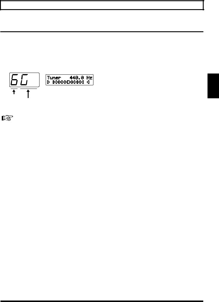
Chapter 3 Controlling Functions and Effects with the Base Module Pedals
Calling Up the Tuner Function with a Pedal
1.While pressing [S1] on the GK-2A, step on Pedal 1 (TUNER).
*Perform this operation with “S1/S2 FUNCTION” set to “Normal.”
The Tuner function is called up, and the following appears in the display.
3.Chap
String Number
Note Name
2. Adjust the tuning.
For more detailed information and instructions for tuning, refer to “Adjusting the Guitar Tuning (Tuner Function)” (p. 18).
3.After you have finished tuning, press any foot pedal or press [S1] or [S2] on the GK-2A.
You will return to Play mode.
29
Chapter 4 Five Basic Modes
The three main modes of the GR-33 allow you to:
•Select tones and perform “Play mode”
•Get effects such as wah or hold using the pedal on the base module “Pedal Effect mode”
•Create and modify patches, and write them into memory
“Patch Edit mode”
•Establish settings for the entire GR-33 “System mode”
•Adjusting the tuning “Tuner mode”
How buttons, dials, and knobs work varies depending on the mode you are in.
Play Mode
In Play mode, the buttons and dials work as follows:
[BANK/PARAMETER] Button
Moves you forward and back through patch banks.
[PLAY] Button
Has no function in this mode.
[SYSTEM] Button
Switches to System mode (settings for the GR-33 itself).
[TUNER] Button
Switches to Tuner mode (p. 18).
[WRITE] Button
Writes the contents of a patch (p. 36).
[COMMON] Button
Switches to Patch Edit mode, COMMON (overall patch settings).
[TONE] Button
Switches to Patch Edit mode, TONE (sound-related patch settings).
[EFFECTS] Button
Switches to Patch Edit mode, EFFECTS (effect-related patch settings).
[STRING SELECT] Button
Has no function in this mode.
[OUTPUT SELECT] Button
Changes the output device selection (p. 19).
[PATCH/VALUE] Dial
Moves forward and back through patches (p. 23).
*If the “DIAL FUNCTION” is set to “VALUE Only,” this will be ignored.
Pedal 1–4
Switches patches (p. 22).
Expression Pedal
Changes the value of the selected parameter (p. 47).
GK-2A [S1]
While this is held down, pedal workings can be changed (p. 22, 29). (TUNER, GROUP ▲, BANK ▲, BANK ▼)
GK-2A [S2]
Switches to Pedal Effect mode (p. 26).
External Bank Shift Pedal
For switching patch banks.
(This does the same thing as BANK ▼ and BANK ▲).
When “S1/S2 FUNCTION” is Set to “Patch Select”
When “S1/S2 FUNCTION” is set to “Patch Select,” use the GK-2A’s [S1] and [S2] buttons to move up and down through the patches. Operation of the following buttons will differ from normal Play mode as follows.
*Buttons and dials not listed here will function the same way as in normal Play mode.
Pedal 1–4
Function as in Pedal Effect mode (p. 31).
GK-2A [S1]
Advances through patches.
GK-2A [S2]
Goes back through patches.
External Bank Shift Pedal
Goes forward and back through patches.
When you want to check something by listening to patches played in order— or want to toggle between a pedal effect such as hold, and a patch—this is a convenient way to do so without having to switch modes. With PATCH INC/DEC BY S1/S2 selected, patch numbers are shown in the display, with “PdL” appearing about once every four seconds.
30
 Loading...