


 Loading...
Contents
USING THE UNIT SAFELY. . . . . . . . . . . . . . . . . . . . . . . . . . . . . |
4 |
IMPORTANT NOTES. . . . . . . . . . . . . . . . . . . . . . . . . . . . . . . . . . |
5 |
Main Features . . . . . . . . . . . . . . . . . . . . . . . . . . . . . . . . . . . . . . . |
6 |
Settings |
7 |
Preparations for Using the GR-55. . . . . . . . . . . . . . . . . . . . . 8
Connections. . . . . . . . . . . . . . . . . . . . . . . . . . . 8 Turning the Power On/Off. . . . . . . . . . . . . . . . . . . . . 8 Selecting Guitar or Bass (GUITAR<->BASS). . . . . . . . . . . . . . . . . . . . . . . . . 9 Adjusting the Pickups (GK SETTING). . . . . . . . . . . . . . . . . . . . . . . . . . . . . . . 9 Adjusting Your Guitar Pickup . . . . . . . . . . . . . . . . 10 Adjusting Your Bass Pickup . . . . . . . . . . . . . . . . . 11 Specifying the Output System (OUTPUT SELECT). . . . . . . . . 12 Tuning Your Instrument (the Tuner Function). . . . . . . . . . . 13
Reference |
19 |
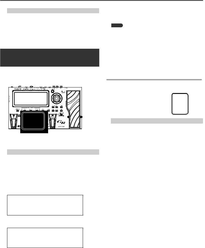
Panel Descriptions.. . . . . . . . . . . . . . . . . . . . . . . . . . . . . . . . . 20
Front Panel. . . . . . . . . . . . . . . . . . . . . . . . . . . . 20 About the Top Screen . . . . . . . . . . . . . . . . . . . 20 About the EDIT Screen. . . . . . . . . . . . . . . . . . . 20 Rear Panel . . . . . . . . . . . . . . . . . . . . . . . . . . . . 21
Side Panel. . . . . . . . . . . . . . . . . . . . . . . . . . . . 21
How the GR-55 Works. . . . . . . . . . . . . . . . . . . . . . . . . . . . . . . 22
Editing the Tones (TONE).. . . . . . . . . . . . . . . . . . . . . . . . . . . 23
Changing the Tone. . . . . . . . . . . . . . . . . . . . . . . . 23 Tone Category . . . . . . . . . . . . . . . . . . . . . . . 23 Editing the Tone. . . . . . . . . . . . . . . . . . . . . . . . . 24 Editing a Tone (Detailed Settings). . . . . . . . . . . . . . . . . 24 Parameter List (PCM TONE 1/PCM TONE 2) . . . . . . . . . . . . 25 Parameter List (MODELING TONE). . . . . . . . . . . . . . . . . 29
Quick Guide |
15 |
Selecting and Playing Sounds. . . . . . . . . . . . . . . . . . . . . . . 16
Adjusting the Output Level. . . . . . . . . . . . . . . . . . . . 16 Selecting a Sound (Patch) . . . . . . . . . . . . . . . . . . . . 16 Playing Your Guitar. . . . . . . . . . . . . . . . . . . . . . . . 17 Creating an Original Sound. . . . . . . . . . . . . . . . . . . . 18 Using the EZ EDIT Function to Create a Sound. . . . . . . . 18 Saving the Sound You Created. . . . . . . . . . . . . . . 18
38
Switching the Effect Type. . . . . . . . . . . . . . . . . . . . . 38 Editing the Effects. . . . . . . . . . . . . . . . . . . . . . . . 39 Effect Editing (Detailed Settings). . . . . . . . . . . . . . . . . 39 Changing the Structure/Specifying the Connection Destination . . 40 Parameter List (EFFECT) . . . . . . . . . . . . . . . . . . . . . 41
AMP. . . . . . . . . . . . . . . . . . . . . . . . . . . . 41 MOD. . . . . . . . . . . . . . . . . . . . . . . . . . . . 42 MFX . . . . . . . . . . . . . . . . . . . . . . . . . . . . 45 DELAY . . . . . . . . . . . . . . . . . . . . . . . . . . . 52 REVERB. . . . . . . . . . . . . . . . . . . . . . . . . . 52 CHORUS. . . . . . . . . . . . . . . . . . . . . . . . . . 53 EQ. . . . . . . . . . . . . . . . . . . . . . . . . . . . . 53
54
Pedal and GK Control Settings (PEDAL/GK CTL). . . . . . . . . . 54 Controller Settings (ASSIGN). . . . . . . . . . . . . . . . . . . 54 Patch Tempo Setting (PATCH TEMPO) . . . . . . . . . . . . . . . 54 GK Pickup Settings for Each Patch (GK SET). . . . . . . . . . . . 54 GUITAR OUT Jack Settings (GUITAR OUT). . . . . . . . . . . . . 54 Changing the Tuning of Each String (ALT-TUNING). . . . . . . . . 54 V-LINK Settings (V-LINK). . . . . . . . . . . . . . . . . . . . . 54 Parameter List (MASTER). . . . . . . . . . . . . . . . . . . . . 55
PEDAL/GK CTL . . . . . . . . . . . . . . . . . . . . . . . 55 ASSIGN . . . . . . . . . . . . . . . . . . . . . . . . . . 57 PATCH TEMPO. . . . . . . . . . . . . . . . . . . . . . . 58 GK SET. . . . . . . . . . . . . . . . . . . . . . . . . . . 58 GUITAR OUT. . . . . . . . . . . . . . . . . . . . . . . . 59 ALT-TUNING. . . . . . . . . . . . . . . . . . . . . . . . 59 V-LINK. . . . . . . . . . . . . . . . . . . . . . . . . . . 59
Before using this unit, carefully read the sections entitled: “USING THE UNIT SAFELY” (p. 4) and “IMPORTANT NOTES” (p. 5). These sections provide important information concerning the proper operation of the unit. Additionally, in order to feel assured that you have gained a good grasp of every feature provided by your new unit, Owner’s manual should be read in its entirety. The manual should be saved and kept on hand as a convenient reference.
Copyright © 2011 ROLAND CORPORATION All rights reserved. No part of this publication may be reproduced in any form without the written permission of ROLAND CORPORATION.
Roland and COSM are registered trademarks of Roland Corporation in the United States and/or other countries.
2

Contents
Saving a Patch (PATCH WRITE). . . . . . . . . . . . . . . . . . . . . . . 60
Saving a Patch (PATCH WRITE) . . . . . . . . . . . . . . . . . . 60 Renaming a Patch. . . . . . . . . . . . . . . . . . . . . 60 Changing the Order of Patches (PATCH EXCHANGE) . . . . . . . . 60 Initializing the Settings of a Patch (PATCH INITIALIZE). . . . . . . 60
61
Controllers Whose Assignment Can Be Changed . . . . . . . . . 61 Making a Pedal Have the Same Operation for All Patches. . 61 Changing the Pedal Assignments for Each Patch. . . . . . . 61
Specifying the Parameter to be Controlled by the
Controller. . . . . . . . . . . . . . . . . . . . . . . . . 62
64
65
Copying Audio Files From Your Computer to USB Memory. . . . . 65 Inserting the USB Memory. . . . . . . . . . . . . . . . . . . . 65 Playing Back Audio. . . . . . . . . . . . . . . . . . . . . . . . 65 Using the Pedal to Control the Audio Player. . . . . . . . . . . . 65
66
Connecting a Computer via USB. . . . . . . . . . . . . . . . . 66 Connecting the GR-55 to a Computer. . . . . . . . . . . . 66 USB function settings. . . . . . . . . . . . . . . . . . . . . . . . . . . . . . . . . . . . . . 66
Connecting the GR-55 to MIDI Devices. . . . . . . . . . . . . . 67 About the MIDI Connectors. . . . . . . . . . . . . . . . . 67 MIDI Settings. . . . . . . . . . . . . . . . . . . . . . . . 67
Connecting the GR-55 to V-LINK Devices (V-LINK) . . . . . . . . . 68 Turning V-LINK On/Off. . . . . . . . . . . . . . . . . . . 68 V-LINK Settings. . . . . . . . . . . . . . . . . . . . . . . 68
69
Setting the GK Pickups (GK SETTING). . . . . . . . . . . . . . . 69 Switching GK Sets. . . . . . . . . . . . . . . . . . . . . 70 Renaming a GK Set. . . . . . . . . . . . . . . . . . . . . 70 Specifying the Output Device (OUTPUT SELECT) . . . . . . . . . 70 Pedal and GK Control Settings (PEDAL/GK CTL). . . . . . . . . . 70 MIDI and USB Settings (MIDI/USB). . . . . . . . . . . . . . . . 70 GUITAR OUT Jack Settings (GUITAR OUT). . . . . . . . . . . . . 70
Always Outputting the Normal Pickup Sound from the GUITAR OUT Jack for All Patches . . . . . . . . . . . . . . 70
Always Outputting the Modeling Tone Sound from the GUITAR OUT Jack for All Patches . . . . . . . . . . . . . . 70
Changing the Output Sound from the GUITAR OUT Jack for Each Patch. . . . . . . . . . . . . . . . . . . . . . . . . 71
Tuning Your Guitar (TUNER). . . . . . . . . . . . . . . . . . . . 71 Adjusting the Display Contrast (LCD). . . . . . . . . . . . . . . 71 Auto Power Off Settings (POWER). . . . . . . . . . . . . . . . . 71 Switching Between Guitar and Bass (GUITAR<->BASS). . . . . . . 71 Saving GR-55 Settings to USB Memory (BACKUP). . . . . . . . . 72
Restoring GR-55 Settings from USB Memory (RESTORE). . . 72 Adjusting the Pedal Sensitivity (CALIB) . . . . . . . . . . . . . . 73 Restoring the Factory Settings (FACTORY RESET). . . . . . . . . 73
Parameter List (SYSTEM). |
. . . . . . . . . . . . . . . . . . . |
. |
74 |
GK SETTING. . . . |
. . . . . . . . . . . . . . . . . . . |
. |
74 |
OUTPUT SELECT. . |
. . . . . . . . . . . . . . . . . . . |
. |
75 |
PEDAL/GK CTL . . . |
. . . . . . . . . . . . . . . . . . . |
|
. 76 |
MIDI/USB . . . . . |
. . . . . . . . . . . . . . . . . . . |
. |
79 |
OTHER. . . . . . . |
. . . . . . . . . . . . . . . . . . . |
|
. 80 |
BACKUP/INITIALIZE |
. . . . . . . . . . . . . . . . . . . . |
|
. 80 |
Appendix |
81 |
|
|
|
|
|
GR-55 Patch List . . . . . . . . . . . . . . |
. . . . . . . . . . . . . . . . . . . . . . 82 |
|
GUITAR MODE. . . . . . . . |
. . . . . . . . . . . . . . . 82 |
|
BASS MODE. . . . . . . . . |
. . . . . . . . . . . . . . . 88 |
|
|
|
|
Troubleshooting.. . . . . . . . . . . . . |
. . . . . . . . . . . . . . . . . . . . . . 90 |
|
|
|
|
Error Messages. . . . . . . . . . . . . . . |
. . . . . . . . . . . . . . . . . . . . . . 92 |
|
|
|
|
Signal Flow.. . . . . . . . . . . . . . . . . . |
. . . . . . . . . . . . . . . . . . . . . . 93 |
|
|
|
|
MIDI Implementation Chart. . . |
. . . . . . . . . . . . . . . . . . . . . . 94 |
|
|
|
|
Main Specifications. . . . . . . . . . . |
. . . . . . . . . . . . . . . . . . . . . . 95 |
|
|
|
|
Index . . . . . . . . . . . . . . . . . . . . . . . . |
. . . . . . . . . . . . . . . . . . . . . . 96 |
|
|
|
3
USING THE UNIT SAFELY
About WARNING and
  CAUTION Notices
Used for instructions intended to alert the user to the risk of death or severe injury should the unit be used improperly.
Used for instructions intended to alert the user to the risk of injury or material damage should the unit be used improperly.
* Material damage refers to damage or other adverse effects caused with respect to the home and all its furnishings, as well to domestic animals or pets.
About the Symbols
The  symbol alerts the user to important instructions or warnings.The specific meaning of the symbol is determined by the design contained within the triangle. In the case of the symbol at left, it is used for general cautions, warnings, or alerts to danger.
The  symbol alerts the user to items that must never be carried out (are forbidden).The specific thing that must not be done is indicated by the design contained within the circle. In the case of the symbol at left, it means that the unit must never be disassembled.
The  symbol alerts the user to things that must be carried out.The specific thing that must be done is indicated by the design contained within the circle. In the case of the symbol at left, it means that the power-cord plug must be unplugged from the outlet.
ALWAYS OBSERVE THE FOLLOWING
 WARNING
Do not attempt to repair the unit, or replace parts within it (except when this manual provides specific instructions directing you to do so). Refer all servicing to your retailer, the nearest Roland Service Center, or an authorized Roland distributor, as listed on the “Information” page.
Never install the unit in any of the following locations.
 WARNING
In households with small children, an adult should provide supervision until the child is capable of following all the rules essential for the safe operation of the unit.
Protect the unit from strong impact. (Do not drop it!)
•Subject to temperature extremes (e.g., direct sunlight in an enclosed vehicle, near a heating duct, on top of heat-generating equipment); or are
•Damp (e.g., baths, washrooms, on wet floors); or are
•Exposed to steam or smoke; or are
•Subject to salt exposure; or are
•Humid; or are
•Exposed to rain; or are
•Dusty or sandy; or are
•Subject to high levels of vibration and shakiness.
Make sure you always have the unit placed so it is level and sure to remain stable. Never place it on stands that could wobble, or on inclined surfaces.
Be sure to use only the AC adaptor supplied with the unit. Also, make sure the line voltage at the installation matches the input voltage specified on the AC adaptor’s body. Other AC adaptors may use a different polarity, or be designed for a different voltage, so their use could result in damage, malfunction, or electric shock.
Use only the attached power-supply cord. Also, the supplied power cord must not be used with any other device.
Do not excessively twist or bend the power cord, nor place heavy objects on it. Doing so can damage the cord, producing severed elements and short circuits. Damaged cords are fire and shock hazards!
This unit, either alone or in combination with an amplifier and headphones or speakers, may be capable of producing sound levels that could cause permanent hearing loss. Do not operate for a long period of time at a high volume level, or at a level that is uncomfortable. If you experience any hearing loss or ringing in the ears, you should immediately stop using the unit, and consult an audiologist.
Do not place containers containing liquid on this product. Never allow foreign objects (e.g., flammable objects, coins, wires) or liquids (e.g., water or juice) to enter this product. Doing so may cause short circuits, faulty operation, or other malfunctions.
Immediately turn the power off, remove the AC adaptor from the outlet, and request servicing by your retailer, the nearest Roland Service Center, or an authorized Roland distributor, as listed on the “Information” page when:
•The AC adaptor, the power-supply cord, or the plug has been damaged; or
•If smoke or unusual odor occurs
•Objects have fallen into, or liquid has been spilled onto the unit; or
•The unit has been exposed to rain (or otherwise has become wet); or
•The unit does not appear to operate normally or exhibits a marked change in performance.
Do not force the unit’s power-supply cord to share an outlet with an unreasonable number of other devices. Be especially careful when using extension cords–the total power used by all devices you have connected to the extension cord’s outlet must never exceed the power rating (watts/ amperes) for the extension cord. Excessive loads can cause the insulation on the cord to heat up and eventually melt through.
Before using the unit in a foreign country, consult with your retailer, the nearest Roland Service Center, or an authorized Roland distributor, as listed on the “Information” page.
 CAUTION
The unit and the AC adaptor should be located so their location or position does not interfere with their proper ventilation.
Always grasp only the plug on the AC adaptor cord when plugging into, or unplugging from, an outlet or this unit.
At regular intervals, you should unplug the AC adaptor and clean it by using a dry cloth to wipe all dust and other accumulations away from its prongs. Also, disconnect the power plug from the power outlet whenever the unit is to remain unused for an extended period of time. Any accumulation of dust between the power plug and the power outlet can result in poor insulation and lead to fire.
Try to prevent cords and cables from becoming entangled. Also, all cords and cables should be placed so they are out of the reach of children.
Never climb on top of, nor place heavy objects on the unit.
Never handle the AC adaptor or its plugs with wet hands when plugging into, or unplugging from, an outlet or this unit.
Before moving the unit, disconnect the AC adaptor and all cords coming from external devices.
Before cleaning the unit, turn off the power and unplug the AC adaptor from the outlet (p. 8).
Whenever you suspect the possibility of lightning in your area, disconnect the AC adaptor from the outlet.
Keep the ground terminal screw and/or USB connector cap you may remove in a safe place out of children’s reach, so there is no chance of them being swallowed accidentally.
4
IMPORTANT NOTES
Power Supply
•Do not connect this unit to same electrical outlet that is being used by an electrical appliance that is controlled by an inverter (such as a refrigerator,
washing machine, microwave oven, or air conditioner), or that contains a motor. Depending on the way in which the electrical appliance is used, power supply noise may cause this unit to malfunction or may produce audible noise. If it is not practical to use a separate electrical outlet, connect a power supply noise filter between this unit and the electrical outlet.
•The AC adaptor will begin to generate heat after long hours of consecutive use. This is normal, and is not a cause for concern.
•Before connecting this unit to other devices, turn off the power to all units. This will help prevent malfunctions and/or damage to speakers or other devices.
Placement
•Using the unit near power amplifiers (or other equipment containing large power transformers) may induce hum. To alleviate the problem, change the orientation of this unit; or move it farther away from the source of interference.
•This device may interfere with radio and television reception. Do not use this device in the vicinity of such receivers.
•Noise may be produced if wireless communications devices, such as cell phones, are operated in the vicinity of this unit. Such noise could occur when receiving or initiating a call, or while conversing. Should you experience such problems, you should relocate such wireless devices so they are at a greater distance from this unit, or switch them off.
•Do not expose the unit to direct sunlight, place it near devices that radiate heat, leave it inside an enclosed vehicle, or otherwise subject it to temperature extremes. Excessive heat can deform or discolor the unit.
•When moved from one location to another where the temperature and/or humidity is very different, water droplets (condensation) may form inside the unit. Damage or malfunction may result if you attempt to use the unit in this condition. Therefore, before using the unit, you must allow it to stand for several hours, until the condensation has completely evaporated.
•Depending on the material and temperature of the surface on which you place the unit, its rubber feet may discolor or mar the surface.
You can place a piece of felt or cloth under the rubber feet to prevent this from happening. If you do so, please make sure that the unit will not slip or move accidentally.
•Do not put anything that contains water on this unit. Also, avoid the use of insecticides, perfumes, alcohol, nail polish, spray cans, etc., near the unit. Swiftly wipe away any liquid that spills on the unit using a dry, soft cloth.
Maintenance
•For everyday cleaning wipe the unit with a soft, dry cloth or one that has been slightly dampened with water. To remove stubborn dirt, use a cloth impregnated with a mild, non-abrasive detergent.
Afterwards, be sure to wipe the unit thoroughly with a soft, dry cloth.
•Never use benzine, thinners, alcohol or solvents of any kind, to avoid the possibility of discoloration and/or deformation.
Repairs and Data
•Please be aware that all data contained in the unit’s memory may be lost when the unit is sent for repairs. Important data should always be backed up on USB memories or written down on paper (when possible). During repairs, due care is taken to avoid the loss of data. However, in certain cases (such as when circuitry related to memory itself is out of order), we regret that it may not be possible to restore the data, and Roland assumes no liability concerning such loss of data.
Using External Memories
•Carefully insert the USB memories all the way in—until it is firmly in place.
•Never touch the terminals of the USB memories. Also, avoid getting the terminals dirty.
•USB memories are constructed using precision components; handle the cards carefully, paying particular note to the following.
•To prevent damage to the cards from static electricity, be sure to discharge any static electricity from your own body before handling the cards.
•Do not touch or allow metal to come into contact with the contact portion of the cards.
•Do not bend, drop, or subject cards to strong shock or vibration.
•Do not keep cards in direct sunlight, in closed vehicles, or other such locations.
•Do not allow cards to become wet.
•Do not disassemble or modify the cards.
•To avoid disturbing your neighbors, try to keep the unit’s volume at reasonable levels. You may prefer to use headphones, so you do not need to be concerned about those around you.
•When you need to transport the unit, package it in the box (including padding) that it came in, if possible. Otherwise, you will need to use equivalent packaging materials.
•The explanations in this manual include illustrations that depict what should typically be shown by the display. Note, however, that your unit may incorporate a newer, enhanced version of the system (e.g., includes newer sounds), so what you actually see in the display may not always match what appears in the manual.
Additional Precautions
•Please be aware that the contents of memory can be irretrievably lost as a result of a malfunction, or the improper operation of the unit. To protect yourself against the risk of loosing important data,
we recommend that you periodically save a backup copy of important data you have stored in the unit’s memory on USB memories.
•Unfortunately, it may be impossible to restore the contents of data that was stored in the unit’s memory or on USB memories once it has been lost. Roland Corporation assumes no liability concerning such loss of data.
•Use a reasonable amount of care when using the unit’s buttons, sliders, or other controls; and when using
its jacks and connectors. Rough handling can lead to malfunctions.
•Never strike or apply strong pressure to the display.
•When connecting / disconnecting all cables, grasp the connector itself—never pull on the cable. This way you will avoid causing shorts, or damage to the cable’s internal elements.
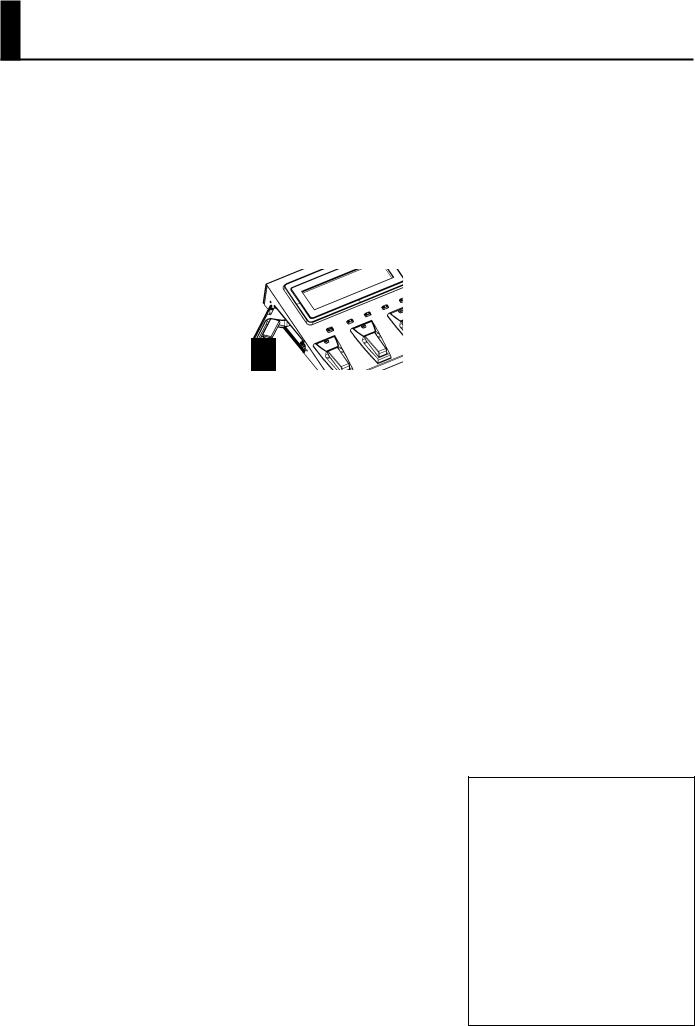
•When you operate the expression pedal, please be careful not to get your fingers pinched between the movable part and the panel.
In households with small children, an adult should provide supervision until the child is capable of following all the rules essential for the safe operation of the unit.
•Microsoft and Windows are registered trademarks of Microsoft Corporation.
•The screen shots in this document are used in compliance with the guidelines of the Microsoft Corporation.
•Windows® is known officially as: “Microsoft® Windows® operating system.”
•Apple and Macintosh are registered trademarks of Apple Inc.
•Mac OS is a trademark of Apple Inc.
•MMP (Moore Microprocessor Portfolio) refers to a patent portfolio concerned with microprocessor architecture, which was developed by Technology Properties Limited (TPL). Roland has licensed this technology from the TPL Group.
•All product names mentioned in this document are trademarks or registered trademarks of their respective owners.
5
Main Features
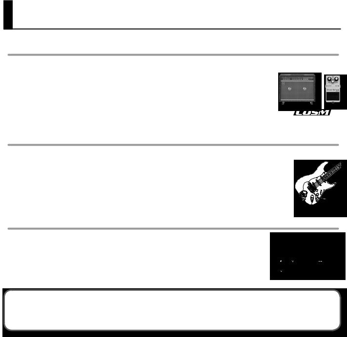
Sound: Sophisticated fusion of a PCM synthesizer and COSM modeling sound generator
Sounds produced by a high-quality PCM synthesizer and a realistic COSM modeling sound generator can be freely combined to take advantage of each method’s unique characteristics.
You can intuitively create new sound combinations with a high degree of freedom. For example, you could create a new lead guitar sound that’s based on a standard distorted guitar combined with a synth lead or organ. Alternatively, you might layer a flute or a synth bell sound with an acoustic guitar to create fantastic new tones.
COSM amps and various effects units are provided independently, allowing you to create an incredible variety ranging, from raw guitar amp sounds to tricky noise sounds.
Expressiveness: Newly developed guitar pitch detection technology
The independent pickup signal from each of the six strings is analyzed at high speed by a newly developed algorithm, ensuring quick and accurate response from the sound generator.
In addition, your picking position as well as the differences between notes played with a pick or with your fingers are also detected and transmitted to the sound generator, giving the GR-55 a range of performance expression that’s much broader and more natural than any previous guitar synthesizer.
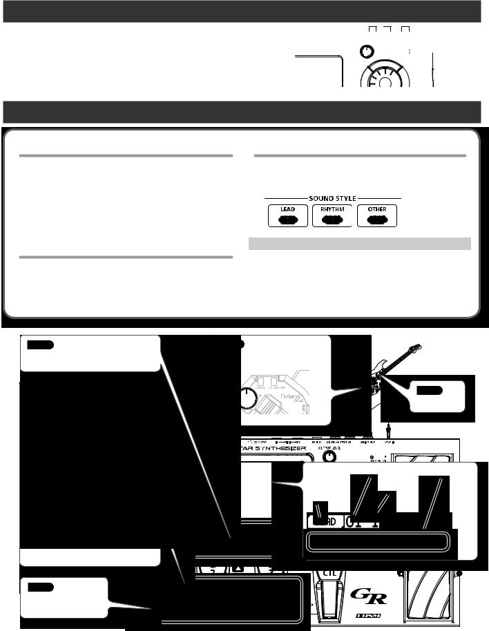
Easy use: Use SOUND STYLE to select a sound, and use EZ EDIT to edit it
The three SOUND STYLE buttons “LEAD,”“RHYTHM,” and “OTHER” provide performance-ready sounds in a wide range of musical styles. A large-screen LCD ensures excellent visibility at your feet.
Press the [EZ EDIT] button to make easy graphical adjustments to the sound; this is a great convenience especially when playing live.
What is the COSM?
Technology that simulates existing physical structures, materials, and the like using different, virtual means is called “modeling technology.” COSM (Composite Object Sound Modeling) is a technical innovation from Roland that combines a number of such sound-modeling technologies to create new and unique sounds.
6
Settings
This chapter explains how to make the necessary settings when using the GR-55 for the first time.
First, get your guitar/bass ready
•In order to use the GR-55, you’ll need a guitar or bass equipped with a divided pickup (GK pickup), which outputs a separate signal for each string.
You can use GK pickups such as the Roland GK-3 or GK-3B.
•For details on how to install a GK pickup, refer to the owner’s manual that came with your GK pickup.
MEMO
•Be aware that string buzz due to a warped neck or worn frets, or faulty octave adjustment, can cause problems such as wrong notes being produced.
•This unit does not support 7-string guitars/basses or other non-standard guitars/basses.
Check the Web for details about installing GK pickups
•On the Roland website, the “GK-3/3B Installation Tips” page provides an explanation and photos on how to attach a GK pickup. Be sure to take a look!
http://www.roland.com/GK/
Preparations for Using the GR-55
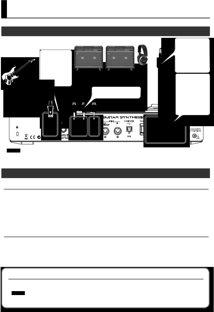
Connections
Guitar equipped with a GK-3/ GK-2A, bass equipped with a GK-3B/GK-2B, or a commercially available GK-ready guitar or bass
The GUITAR OUT jack outputs the sound of the normal pickups and the sound of the modeling tone (p. 22).
For details, refer to “GUITAR OUT Jack Settings (GUITAR OUT)” (p. 54).
Amp or PA (line) |
Headphones |
|
|||||
|
|
|
|
|
|
|
|
|
|
|
|
|
|
|
|
|
|
|
|
|
|
|
|
|
|
|
|
|
|
|
|
|
|
|
|
|
|
|
|
|
|
|
|
|
|
|
|
|
|
|
|
|
|
|
|
If you’re using monaural output, connect only to the L/MONO jack.
Place the AC adaptor so the side with the indicator (see illustration) faces upwards and the side with textual information faces downwards.
The indicator will light when you plug the AC adaptor into an AC outlet.
To prevent the inadvertent disruption of power to your unit (should the plug be pulled out accidentally), and to avoid applying undue stress to the AC adaptor jack, anchor the power cord using the cord hook, as shown in the illustration.
NOTE!
•To prevent malfunction and/or damage to speakers or other devices, always turn down the volume, and turn off the power on all devices before making any connections.
•Switch on the power to all of your equipment before you raise the volume of the amp.
Turning the Power On/Off
Turning the power on
Once the connections have been completed, turn on power to your various devices in the order specified. By turning on devices in the wrong order, you risk causing malfunction and/or damage to speakers and other devices.
*Always make sure to have the volume level turned down before switching on power.. Even with the volume all the way down, you may still hear some sound when the power is switched on, but this is normal, and does not indicate a malfunction..
*This unit is equipped with a protection circuit.. A brief interval (a few seconds) after power up is required before the unit will operate normally..
1.Press the GR-55’s [POWER] switch to turn the power on..
2.Turn on the power of your amp..
Turning the power off
1.Check the following before you turn the power off..
•Have you minimized the volume on the connected equipment?
•Have you saved the data (settings, sounds, etc.) that you want to keep?
2.Turn off the power of your guitar amp or other connected equipment..
3.Press the GR-55’s [POWER] switch to turn the power off..
If you don’t want the power to turn off automatically, turn the “AUTO POWER OFF” setting off!
With the factory settings, the GR-55’s power will automatically be switched off 10 hours after you stop playing or operating the unit. If you want to have the power remain on all the time, change the “AUTO POWER OFF” setting to “OFF” as described on p. 71.
NOTE!
The settings you were editing will be lost when the power is turned off. If you want to keep your settings, you must save your settings before turning the power off.
8
Preparations for Using the GR-55
Selecting Guitar or Bass (GUITAR<->BASS)
Before you use the GR-55, you must make a mode setting that specifies whether you’re using it with a guitar or with a bass.
*With the factory settings, this is set to “GUITAR..”
*If BASS MODE is selected, some parameter names are displayed differently than in GUITAR MODE..
(Example) String numbers “1, 2, 3, 4, 5, 6” --> “H, 1, 2, 3, 4, L..”
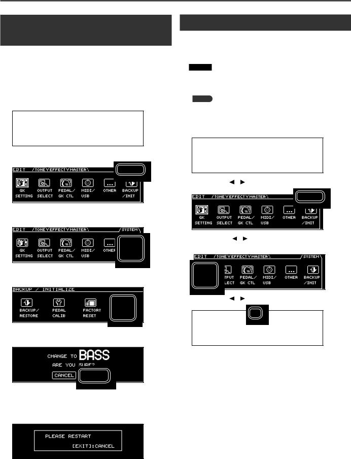
1.Press the [EDIT] button to access the EDIT screen..
Adjusting the Pickups (GK SETTING)
To ensure that the GR-55 is in the best possible playing condition, please make the appropriate adjustments for the divided pickup (GK settings). Making these settings will ensure that the GR-55 is operating optimally.
NOTE!
GK settings are extremely important in order to play the GR-55 with the best possible sound. You must be sure to make these settings correctly.
MEMO
If you connect different guitars to the GR-55 at different times, you can individually save settings for each guitar. For details, refer to “Setting the GK Pickups (GK SETTING)” (p. 69).
1.Press the [EDIT] button to access the EDIT screen..
2.Use the PAGE [ ] [
] [ ] buttons to select the SYSTEM tab..
2. Use the PAGE [ ] [ ] buttons to access the SYSTEM tab..
3.Use the cursor [ ] [
] [ ] buttons to select the BACKUP/INIT icon, and press the [ENTER] button..
4.Use the cursor [ ] [
] [ ] buttons to select the GUITAR<->BASS icon and press the [ENTER] button..
5.If you want to change the mode, use the cursor [ ] [
] [ ] buttons to select “OK,” and press the [ENTER] button..
If you decide not to change the mode, choose “CANCEL” and press the [ENTER] button.
6.When the following screen appears, turn the GR-55’s power off..
The next time you turn the GR-55’s power on, the screen will indicate the specified mode (“GUITAR MODE” or “BASS MODE”).
Once you’ve set the mode, the GR-55 will start up in the specified mode each time it’s powered up.
3. Use the cursor [ ] [ ] buttons to select the GK SETTING icon, and press the [ENTER] button..
4. Use the PAGE [ ] [ ] buttons to select the PU tab..
5.Adjust your pickup..
If you’re using a guitar |
“Adjusting Your Guitar Pickup” (p. 10) |
|
|
If you’re using a bass |
“Adjusting Your Bass Pickup” (p. 11) |
|
|
9
Preparations for Using the GR-55
Adjusting Your Guitar Pickup
1.Use the cursor [ ] [
] [ ] buttons to move the cursor to “PU TYPE,” and use the dial to select the type of pickup that’s installed on your guitar..
|
|
|
|
|
|
|
|
|
|
|
|
|
|
|
|
|
|
|
|
Value |
Description |
||
|
|
|
|
|
|
|
|
GK-3 |
Choose this if you’re using a GK-3. |
||
|
|
|
|
|
|
|
|
GK-2A |
Choose this if you’re using a GK-2A. |
||
|
|
|
|
|
|
|
|
PIEZO |
This setting is appropriate if you’re using a piezo pickup that |
||
|
|
has a flat response. |
|||
|
|
|
|||
|
|
|
|
|
|
|
|
PIEZO F |
This setting is appropriate for a Fishman piezo pickup. |
||
|
|
|
|
|
|
|
|
PIEZO G |
This setting is appropriate for a Graph Tech piezo pickup. |
||
|
|
|
|
|
|
|
|
PIEZO L |
This setting is appropriate for an L.R. Baggs piezo pickup. |
||
|
|
|
|
|
|
|
|
PIEZO R |
This setting is appropriate for an RMC piezo pickup. |
||
|
|
|
|
|
|
A piezo pickup is a type of pickup that is mounted on the bridge of the guitar, and uses a piezoelectric element to detect the vibrations of the strings.
If you’re using a guitar equipped with a GK pickup that’s not of the piezo type, choose “GK-2A.”
*If you’re not sure which piezo type setting is appropriate, try selecting different choices while you play your guitar, and choose the piezo type that produces the most natural sound.. In this case, the difference will be easier to notice if you turn off the PCM 1 and 2 tone switches (p.. 25)..
*If you’ve chosen PIEZO, PIEZO F, PIEZO G, PIEZO L, or PIEZO R as the PU Type setting, you’ll be able to make further adjustments to the tone quality of the high range and low range (p.. 75)..
2.Use the cursor [ ] [
] [ ] buttons to move the cursor to “SCALE,” and use the dial to specify your guitar’s scale length (the distance between the bridge and nut)..
Choose the closest value in the range of 500–660 mm.
Choose “ST” (648 mm) for a standard Stratocaster type, or choose “LP” (628 mm) for a Les Paul type. For details on the other parameters, refer to “GK SETTING” (p. 74).
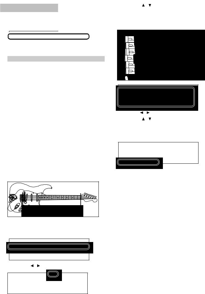
3. Use the PAGE [ ] [ ] buttons to select the DIS tab..
4. Use the cursor [ ] [ ] buttons to select each string, and for each string, specify the distance from the center of the pickup to the bridge saddle..
*If PU TYPE is set to one of the piezo-type pickups, this setting is not necessary..
5. |
Use the PAGE [ |
] [ |
] buttons to select the SEN tab.. |
6. |
Use the cursor [ |
] [ |
] buttons to move the cursor to 6TH |
|
STRING SENS.. |
|
|
Play the 6th string as strongly as you ever expect to play it in actual performance, and use the dial to adjust the sensitivity as high as possible without allowing the meter to reach the full-scale position.
*If the level meter reaches the full-scale position, the level is excessive.. Lower the sensitivity..
*Depending on the guitar you’re using, the level meter might reach full-scale even if the sensitivity is at minimum.. If this is the case, adjust the distance between the divided pickup and the string so it’s somewhat greater than the recommendation..
7.In the same way, adjust the sensitivity for the 5th through 1st strings as well..
8.Check the volume balance of the six strings..
Play each of the strings 6–1 at normal strength; if a string sounds unusually loud, lower the sensitivity of that string to minimize any discrepancy in volume between the strings.
9.Press the [EXIT] button a number of times to return to the top screen..
These settings are required when you’ve newly installed a divided pickup on your guitar, or when you’ve adjusted the height of the divided pickup. These settings will be retained even while the power is switched off. Once you’ve made them correctly, there’s no need to make them again each time you perform. For details on the other parameters, refer to “GK SETTING” (p. 74).
10
Preparations for Using the GR-55
Adjusting Your Bass Pickup
1. Use the cursor [ ] [ ] buttons to move the cursor to “PU TYPE,” and use the dial to select the type of pickup that’s installed on your bass..
3. Use the cursor [ ] [ |
] buttons to move the cursor to “GK PU |
|
POS,” and use the dial to select the position of the divided |
||
pickup.. |
|
|
For a 4-string bass: |
|
|
4STR-1 |
4STR-2 |
4STR-3 |
1st string |
|
|
2nd string |
|
|
3rd string |
|
|
4th string |
|
|
Value |
Description |
|
|
|
|
GK-3B |
Choose this if you’re using a GK-3B. |
|
|
|
|
GK-2B |
Choose this if you’re using a GK-2B. |
|
|
|
|
PIEZO |
This setting is appropriate if you’re using a piezo pickup that |
|
has a flat response. |
||
|
||
|
|
|
PIEZO G |
This setting is appropriate for a Graph Tech piezo pickup. |
|
|
|
|
PIEZO R |
This setting is appropriate for an RMC piezo pickup. |
|
|
|
A piezo pickup is a type of pickup that is mounted on the bridge of the bass, and uses a piezoelectric element to detect the vibrations of the strings.
If you’re using a bass equipped with a GK pickup that’s not of the piezo type, choose “GK-2B.”
*If you’re not sure which piezo type setting is appropriate, try selecting different choices while you play your bass, and choose the piezo type that produces the most natural sound..
*If you’ve chosen “PIEZO,”“PIEZO G,” or “PIEZO R” as the PU Type setting, you’ll be able to make further adjustments to the tone quality of the high range and low range (p.. 75)..
2.Use the cursor [ ] [
] [ ] buttons to move the cursor to “SCALE,” and use the dial to specify your bass’s scale length (the distance between the bridge and nut)..
Choose the closest value in the range of 710–940 mm. For a standard Jazz Bass type or Precision Bass type, choose LONG JB/PB (864 mm).
For details on the other parameters, refer to “GK SETTING” (p. 74).
For a 5-string bass
5STR Lo1 |
5STR Lo2 |
5STR Hi1 |
5STR Hi2 |
1st string |
|
Hi C string |
|
2nd string |
|
1st string |
|
3rd string |
|
2nd string |
|
4th string |
|
3rd string |
|
Low B string |
|
4th string |
|
For a 6-string bass:
6STR
Hi C string 1st string
 2nd string
 3rd string
 4th string
Low B string
4.Use the PAGE [ ] [
] [ ] buttons to select the DIS tab..
5.Use the cursor [ ] [
] [ ] buttons to select each string, and for each string, specify the distance from the center of the divided pickup to the bridge saddle..
*If PU TYPE is set to one of the piezo-type pickups, this setting is not necessary..
6. Use the PAGE [ ] [ ] buttons to select the SEN tab..
11
Preparations for Using the GR-55
7.Use the cursor [ ] [
] [ ] buttons to move the cursor to the STRING SENS field for the lowest string..
Play the lowest string as strongly as you ever expect to play it in actual performance, and use the dial to adjust the sensitivity as high as possible without allowing the meter to reach the full-scale position.
*If the level meter reaches the full-scale position, the level is excessive.. Lower the sensitivity..
*Depending on the bass you’re using, the level meter might reach full-scale even if the sensitivity is at minimum.. If this is the case, adjust the distance between the divided pickup and the string so it’s somewhat greater than the recommendation..
8.In the same way, adjust the sensitivity of the remaining strings as well..
9.Check the volume balance of the strings..
Play each of the strings at normal strength; if a string sound unusually loud, lower the sensitivity of that string to minimize any discrepancy in volume between the strings.
10.Press the [EXIT] button a number of times to return to the top screen..
These settings are required when you’ve newly installed a divided pickup on your bass, or when you’ve adjusted the height of the divided pickup. These settings will be retained even while the power is switched off. Once you’ve made them correctly, there’s no need to make them again each time you perform. For details on the other parameters, refer to “GK SETTING” (p. 74).
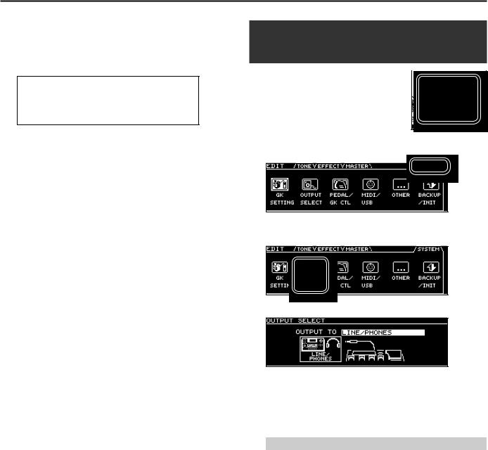
Specifying the Output System
(OUTPUT SELECT)
Here’s how to specify the device (amp) that’s 


 connected to the OUTPUT jacks. The tone will


 be adjusted within the GR-55 to ensure that


the optimal sound is produced on the device  you specified.
1. Press the [EDIT] button to access the EDIT screen..
2.Use the PAGE [ ] [
] [ ] buttons to select the SYSTEM tab..
3.Use the cursor [ ] [
] [ ] buttons to select the OUTPUT SELECT icon, and press the [ENTER] button..
The OUTPUT SELECT screen will appear.
4.Use the dial to select the type of device (amp) that’s connected to the OUTPUT jacks..
*With the factory settings, this is set to “LINE/PHONES..”
*If headphones are connected, this will automatically be “LINE/ PHONES” regardless of the OUTPUT SELECT setting..
Setting |
Description |
|
|
|
|
LINE/PHONES |
This is the appropriate setting when using headphones, |
|
or for when the GR-55 is connected to a keyboard amp, |
||
|
mixer, or digital recorder. |
|
|
|
|
JC-120 |
Choose this setting if the GR-55 is connected to the guitar |
|
input of a Roland JC-120 guitar amp. |
||
|
||
|
|
|
SMALL |
Choose this setting if the GR-55 is connected to a small |
|
guitar amp. |
||
|
||
|
|
|
|
Choose this setting if the GR-55 is connected to the |
|
COMBO |
guitar input of a combo-type guitar amp (i.e., an amp that |
|
contains the amp and speaker in a single unit) other than |
||
|
the JC-120. Depending on the guitar amp you’re using, |
|
|
using the “JC-120” setting might produce better results. |
|
|
|
|
STACK |
Choose this setting if the GR-55 is connected to the guitar |
|
input of a stack-type guitar amp (i.e., an amp in which the |
||
|
amp and speaker are separate units). |
|
|
|
|
JC-120 RETURN |
Choose this setting if the GR-55 is connected to the |
|
JC-120’s RETURN jack. |
||
|
||
|
|
|
COMBO |
Choose this setting if the GR-55 is connected to the |
|
RETURN |
RETURN jack of a combo-type guitar amp. |
|
|
Choose this setting if the GR-55 is connected to the |
|
STACK RETURN |
RETURN jack of a stack-type guitar amp. You should also |
|
choose the “STACK RETURN” setting when using the GR-55 |
||
|
||
|
with a guitar power amp and a speaker cabinet. |
|
|
|
12
Preparations for Using the GR-55
Setting |
Description |
|
|
|
|
B-AMP WITH |
Choose this setting if the GR-55 is connected to a bass |
|
TWEETER |
amp that has a tweeter. |
|
|
|
|
B-AMP NO |
Choose this setting if the GR-55 is connected to a bass |
|
amp that does not have a tweeter. The high-frequency |
||
TWEETER |
||
range will be corrected appropriately. |
||
|
||
|
|
5.Press the [EXIT] button a number of times to return to the top screen..
Tuning Your Instrument
(the Tuner Function)
Here’s how you can use the GR-55’s Tuner function to tune your guitar or bass.
1.Press the [2] pedal and [3] pedal simultaneously..
4.Watch the screen, and tune your instrument so that only the center indicator is lit..
Repeat steps 3 and 4 until all of the strings are tuned.
MEMO
When tuning a guitar that’s equipped with a vibrato arm, tuning one string may cause other strings to drift out of tune. In this case, start by tuning each string approximately, so that the correct note name is shown, and then retune each string repeatedly until all strings are tuned correctly.
5.When you’ve finished tuning, press a pedal (any one of the [1]–[3] pedals or the [CTL] pedal)..
You will return to the original screen.
You can also return to the original screen by pressing the [EXIT] button.
Settings in the TUNER screen
In the TUNER screen you can use the cursor buttons and the dial to make the following settings.
The TUNER screen will appear.
2.Use the PAGE [ ] [
] [ ] buttons to switch between the tabs to choose the mode of the Tuner function..
Tab |
Description |
|
MULTI MODE |
Allows you to tune six strings at the same time. |
|
|
|
|
SINGLE MODE |
Allows you to tune by playing a single note on the |
|
specific string you’re tuning. |
||
|
||
|
|
3.Play an unfretted note on the string that you want to tune, and tune the string so that the desired note name is shown in the display..
When using MULTI MODE
When using SINGLE MODE
|
|
|
|
|
|
|
|
|
|
|
|
Parameter |
Value |
Description |
|||
|
|
|
|
||
|
435 Hz |
Specifies the reference pitch. |
|||
MASTER TUNE |
* With the factory settings this is set to |
||||
–445 Hz |
|||||
|
“440 Hz..” |
||||
|
|
||||
|
|
|
|
||
|
OFF |
Sound will be output while you’re tuning. |
|||
TUNER MUTE |
|
|
|
||
ON |
Sound will not be output while you’re tuning. |
||||
|
* The factory setting is “ON..” |
||||
|
|
||||
*In SYSTEM parameter GK SETTING, if DOWN TUNE (p.. 75) is set to a value other than “0,” the tuner screen will indicate the note names as if they were not down tuned..
13
MEMO
14

Quick Guide
This chapter explains basic operation.
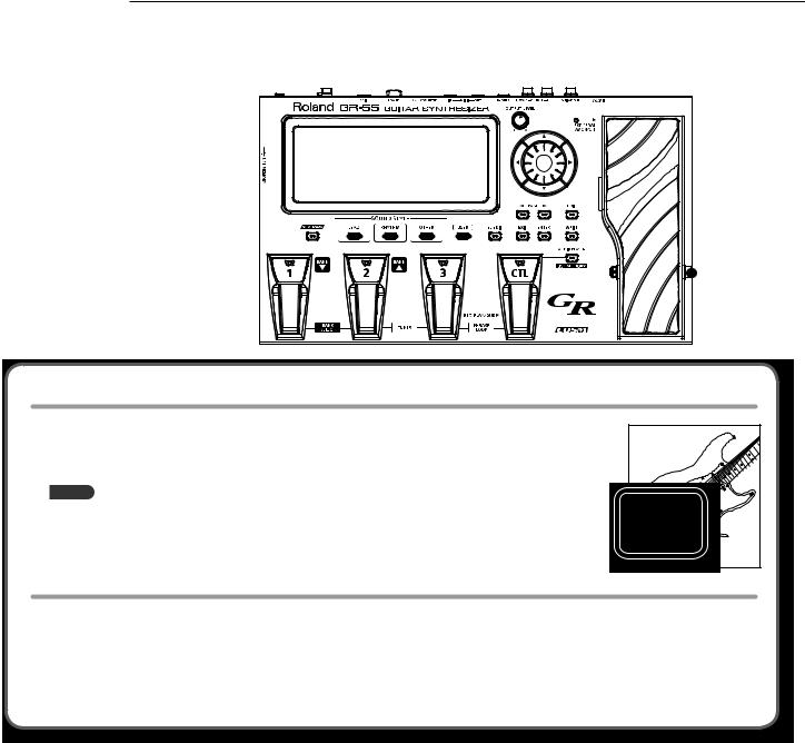
Before you play, you should set your GK pickup’s select switch to “MIX”!
If a different setting is selected, the sound might not be output correctly.
Selecting and Playing Sounds
Now that you’ve finished with preparations, here’s how to operate the GR-55 while you play.
Adjusting the Output Level
1.Adjust the GR-55’s output level by turning the [OUTPUT LEVEL] knob..
Turning the knob toward the right will increase the volume;
turning the knob all the way toward the left will set the volume to zero. Normally, you can place the knob near the center position.
Step on the expression pedal. Raise the GK pickup’s volume knob.
Selecting a Sound (Patch)
What is a Patch?
A “patch” is a unit of sound on the GR-55; in addition to settings determining the type of sound, the patch also includes effect settings.
You are free to modify (edit) the settings of a patch and store it in the GR-55 as a “user patch.” (Patches that are already built into the GR-55 are called “preset patches.”)
For more about patches, refer to “How the GR-55 Works” (p. 22).
What is a Bank?
A “bank” is a collection of three patches.
What is a Sound Style?
The GR-55 lets you select preset patches from three “sound styles.” First select the style of sound that you want to play, and then select a patch from within that style.
Sound style |
Summary |
|
LEAD |
Sound styles suitable for soloing, such as lead guitar |
|
sounds and wind instruments. |
||
|
||
|
|
|
RHYTHM |
Sound styles suitable for backing, such when comping |
|
chords or playing arpeggios. |
||
|
||
|
|
|
OTHER |
Sound styles that include effective, characteristic |
|
synthesized sounds. |
||
|
||
|
|
Step 1
Choose the sound style of the sound you want to play.
the GK pickup [S1]/[S2] buttons to switch banks. 

Step 3
Use the [1]–[3] pedals to select a patch.
4
the GK-3’s volume knob to adjust volume of the patch.
Step 5
Play.
Patch bank |
Patch name |
Patch number |
|
Sound style |
|
16
Selecting and Playing Sounds
Selecting a User Patch
New patches that you create are saved in the GR-55 as “user patches” (p. 18).
Press the [USER] button to select user patches in Step 1 of “Selecting a Sound (Patch).”
The rest of the procedure is the same as when selecting a preset patch.
Playing Your Guitar
You can apply effects to the sound by pressing the following pedals while you play.
[CTL] pedal
When you press this pedal while playing, an effect specified for each patch will be applied; for example, raising the synthesizer sound by an octave, or extending the decay of the synthesizer note you’re playing.
You are also free to change this effect to your taste (p. 61).
Expression pedal
When you operate this pedal while playing, the effect assigned to each patch will be applied.
Normally, the volume will change, but depending on the patch, a variety of other effects may be assigned.
If you depress this pedal completely, placing your weight on the toe, the EXP PEDAL SW indicator will light, and the expression pedal will switch to a different function. Normally, it will control an effect such as wah pedal, but this too may be assigned to a different effect depending on the patch.
You can change each of these effects according to your taste (p. 61).
*When operating the expression pedal, be careful so as not to get your toes pinched between the moving portion and the main part of the GR-55.. If there are young children in your household, don’t let them use or play with the GR-55 without adult supervision..
17

Selecting and Playing Sounds
Creating an Original Sound
Using the EZ EDIT Function to Create a Sound
You can easily edit the selected patch to your taste by using the GR-55’s EZ EDIT function.
Step 1 |
Step 2 |
Select a patch (p. 16). |
Press the [EZ EDIT] button to access |
|
the EZ EDIT screen. |
Step 3
Edit the sound by using [ ] [
] [ ] [
] [ ] [
] [ ] (cursor buttons) to move the cursor within the grid.
Step 4
Turn the dial to adjust the volume of the overall patch.
Display |
Parameter |
Description |
||
|
|
|
|
|
|
|
|
WET |
Gives the sound richer ambience (reverb/delay). |
|
|
|
|
|
|
|
|
DRY |
Gives the sound less ambience (reverb/delay). |
|
|
|
|
|
|
|
|
MILD |
Helps the sound blend in with the mix. |
|
|
|
|
|
|
|
|
BRIGHT |
Helps the sound stand out from the mix. |
|
|
|
||
|
|
|
|
|
Saving the Sound You Created
When you’ve created a sound that you like, you should save it as a user patch.
Be aware that if you switch to another patch without saving the patch you edited, the changes you made will be lost.
Step 1
Press the [WRITE] button. The WRITE screen will appear. |
Step 2 |
|
Turn the dial to specify the save-destination patch number.
* For more about saving patches, refer to “Saving a Patch (PATCH WRITE)” (p.. 60)..
18
Reference
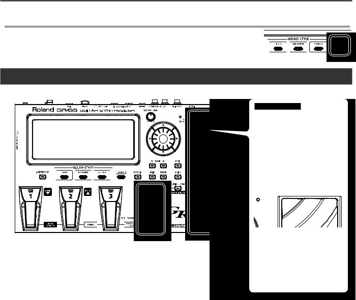
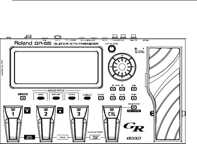
Panel Descriptions
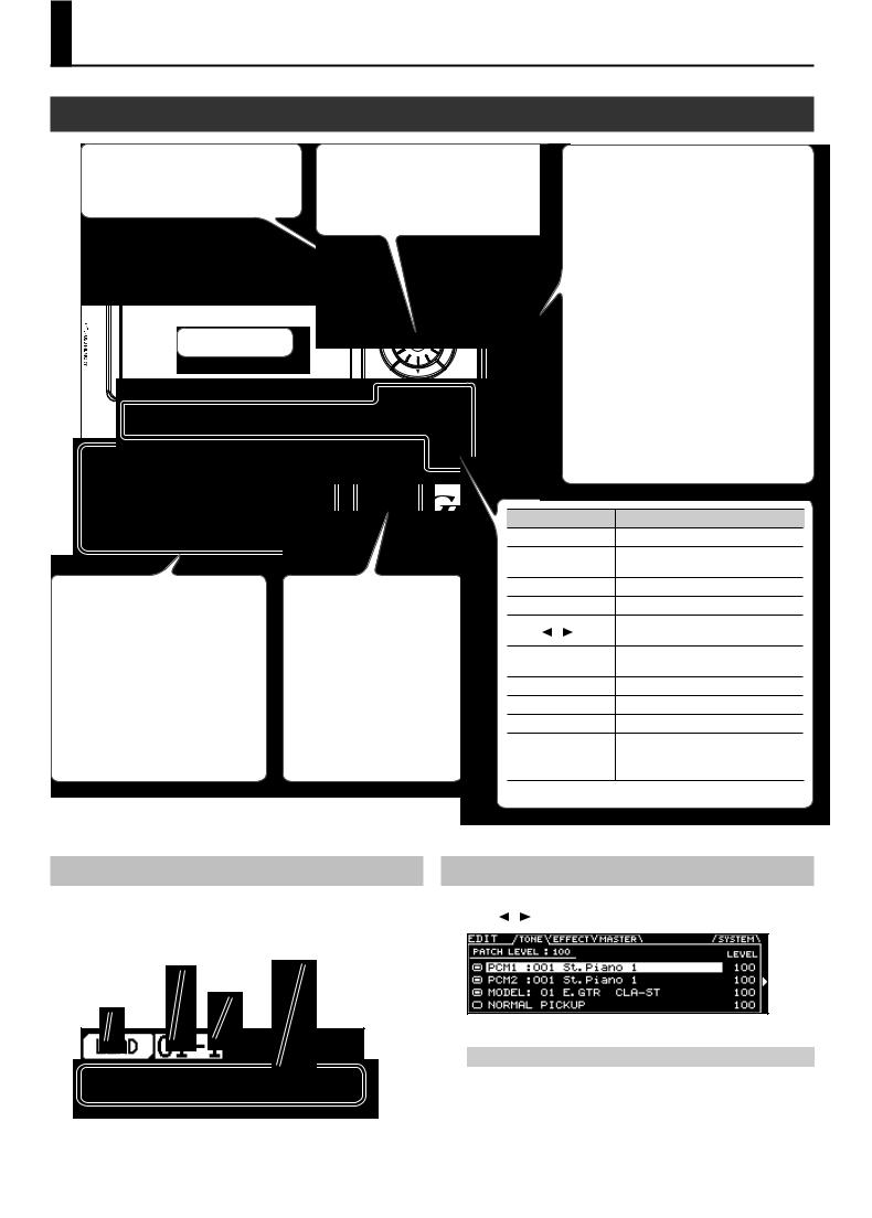
Front Panel
[OUTPUT LEVEL] knob
Adjusts the volume of the output jacks and the headphone jack.
Display
[1]([BANK  ]),
]),
[2]([BANK  ]), [3] pedals
Press these pedals to select patches or patch banks.
By pressing the [BANK  ] pedal and [BANK
  ] pedal simultaneously, you can turn “Bank Select” on/off, allowing you to select the desired patch bank (p. 16).
By pressing the [2] pedal and [3] pedal simultaneously, you can tune your guitar (p. 13).
Dial
Use this to switch patches or edit values.
[ ] [
] [ ] [
] [ ] [
] [ ] (cursor buttons)
Use these to move the cursor up/down/ left/right.
Expression pedal
When you operate this pedal while playing, the effect assigned to each patch will be applied.
Normally, the volume will change, but depending on the patch, a variety of other effects may be assigned.
If you depress this pedal completely, placing your weight on the toe, the EXP PEDAL SW indicator will light, and the expression pedal will switch to a different function. Normally, it will control an effect such as wah pedal, but this too may be assigned to a different effect depending on the patch.
You can change each of these effects according to your taste (p. 61).
[CTL] (control) pedal
By holding down this pedal you can apply the effect that is assigned by the patch, such as sustaining or modifying the currently playing note.
You are also free to assign other functions (p. 61).
By pressing the [3] pedal and [CTL] pedal simultaneously, you can use the PHRASE LOOP function (p. 64).
* When operating the expression pedal, be careful so as not to get your toes pinched between the
moving portion and the main part of the GR-55.. If there are young children in your household,
don’t let them use or play with the GR-55 without adult supervision..
Button |
Description |
|
[V-LINK] |
Switches V-LINK on/off (p. 68). |
|
[LEAD]/[RHYTHM]/ |
Switches the sound style (p. 16). |
|
[OTHER] |
||
|
||
[USER] |
Selects user patches (p. 17). |
|
[EZ EDIT] |
Accesses the EZ EDIT screen (p. 18). |
|
PAGE [ ] [ ] |
Pressed to navigate to the next left/right |
|
tab in the screen. |
||
|
||
[EXIT] |
Cancels an operation, or takes you to the |
|
next higher level in the screen. |
||
|
||
[ENTER] |
Confirms an operation. |
|
[EDIT] |
Accesses the EDIT screen (p. 20). |
|
[WRITE] |
Saves the patch (p. 60). |
|
|
Accesses the AUDIO PLAYER screen (p. 65). |
|
[AUDIO PLAYER] |
The AUDIO PLAYER is available only if |
|
|
USB memory is inserted in the GR-55. |
About the Top Screen
A short while after you turn on the power of the GR-55, this screen will appear. In this manual, the explanations of various procedures will start from this screen unless otherwise specified.
Patch bank |
Patch name |
|
|
Patch number |
|
Sound style
About the EDIT Screen
The EDIT screen will appear when you press the [EDIT] button. Use the PAGE [ ] [ ] buttons to switch between tabs in the EDIT screen.
For details on each screen, refer to the following pages.
Screen |
Description |
Page |
|
|
|
TONE |
Edit the tone settings. |
p. 23 |
|
|
|
EFFECT |
Edit the effect settings. |
p. 38 |
|
|
|
MASTER |
Edit overall settings for the patch. |
p. 54 |
SYSTEM |
Edit settings for the entire GR-55. |
p. 69 |
|
|
|
20
Panel Descriptions
Rear Panel
1 |
2 |
3 |
4 |
5 |
6 |
7 |
8 |
9 |
10 |
11 |
1.Security Slot ( ) http://www.kensington.com/
2.GK IN connector
Use the included GK cable (or a separately sold GKC-5 or GKC-10) to connect your divided pickup to this connector.
*For details on connecting a commercially available GK-equipped guitar, refer to the guitar manufacturer or your dealer..
3.GUITAR OUT jack
This jack outputs the sound of the guitar’s normal pickup and the sound of the GR-55’s modeling tone (p. 22). Connect it to your guitar amp.
For details on settings for the sound that is output from the GUITAR OUT jack, and how to make connections, refer to “GUITAR OUT Jack Settings (GUITAR OUT)” (p. 70).
4.OUTPUT R, L/MONO jacks
These jacks output the sound of your performance using the GR-55. If connecting to a monaural amp, use the L/MONO jack.
Set the OUTPUT SELECT setting to specify the type of device (amp) that’s connected to these jacks, as described in “Specifying the Output System (OUTPUT SELECT)” (p. 12).
5.PHONES jack
Connect headphones (sold separately) to this jack (p. 8).
6.MIDI connectors (OUT, IN)
Connect other MIDI equipment to these connectors (p. 67).
7.USB COMPUTER connector
Use a USB cable to connect the GR-55 to your computer (p. 66).
8.[POWER] switch
This turns the power on/off (p. 8).
9.DC IN (AC adaptor) jack
Connect the included AC adaptor here (p. 8).
10.Cord hook
Use this to fasten the AC adaptor cord so that it will not be unplugged accidentally (p. 8).
11.Functional ground terminal
Depending on the circumstances of a particular
setup, you may experience a discomforting sensation, or perceive that the surface feels gritty to the touch when you touch this device or the 
 metal portions of other objects connected to it, such as guitars. This is due to an infinitesimal
  electrical charge, which is absolutely harmless.
However, if you are concerned about this,
connect the ground terminal (see figure) with an external ground. When the unit is grounded, a slight hum may occur, depending on the particulars of your installation. If you are unsure of the connection method, contact the nearest Roland Service Center, or an authorized Roland distributor, as listed on the “Information” page.
Unsuitable places for connection
•Water pipes (may result in shock or electrocution)
•Gas pipes (may result in fire or explosion)
•Telephone-line ground or lightning rod (may be dangerous in the event of lightning)
Side Panel


 1
1
1.USB MEMORY connector
Connect USB memory (sold separately) here.
*Never insert or remove a USB memory while this unit’s power is on.. Doing so may corrupt the unit’s data or the data on the USB memories..
*Carefully insert the USB memory all the way in-until it is firmly in place..
21
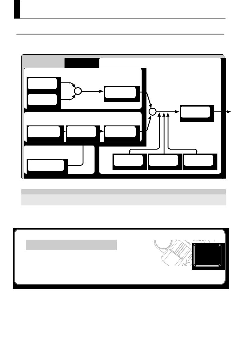
How the GR-55 Works
What is a Patch?
A “patch” is a unit of sound on the GR-55. In addition to settings determining the type of sound, a patch also contains effect settings.
You can modify (edit) the settings of a patch, and save it as a “user patch.” (The patches already built into the GR-55 are called “preset patches.”) The following illustration shows how a patch is structured internally.
PATCH
Synthesizer sound
PCM TONE 1
PCM TONE 2
Modeling sound
MODELING TONE
Effects
This is a synthesizer sound that plays according to the performance data from your guitar. Two PCM tones can be layered.
+ |
MFX |
|
Multi-effect |
This is a modeled sound based on the audio from each guitar string.
AMP |
MOD |
Preamp |
Guitar effects |
Normal pickup sound
This is the sound of the guitar’s normal pickup.
CHORUS
NORMAL PICKUP
These effects processors apply various effects to the sound.
MFX is a stereo-in multi-effects processor.
AMP uses COSM technology to simulate the response of the preamp, the size of the speakers, and the shape of the cabinet.
MOD is a monaural-input guitar effects processor used in conjunction with AMP.
+ |
EQ |
|
|
|
Equalizer |
DELAY |
REVERB |
There are some restrictions on the functions that can be used with each tone and with the normal pickup; please refer to the following table.
Parameter |
HOLD |
ALTERNATE TUNING |
TONE EDIT |
GUITAR OUT |
|
|
|
|
|
Description |
Sustain the sound (Hold) |
Change the tuning of each string |
Edit the tone |
Output from GUITAR OUT jack |
|
|
|
|
|
Page |
p. 55, p. 76 |
p. 54 |
p. 24 |
p. 54 |
|
|
|
|
|
PCM tones 1, 2 |
√ |
√ |
√ |
× |
|
|
|
|
|
Modeling tone |
× |
√ |
√ |
√ |
|
|
|
|
|
Normal pickup |
× |
× |
× |
√ |
|
|
|
|
|
The available tones will depend on the position of the GK pickup’s select switch.
|
GK pickup select switch |
|
|
|
|
|
GK |
MIX |
|
|
|
PCM tones 1, 2 |
√ |
√ |
|
|
|
Modeling tone |
√ |
√ |
|
|
|
Normal pickup |
× |
√ |
|
|
|
*Even if a tone is available, there will be no sound if its tone switch (p.. 23) is “OFF..” Normally, you should use the “MIX” setting..
22
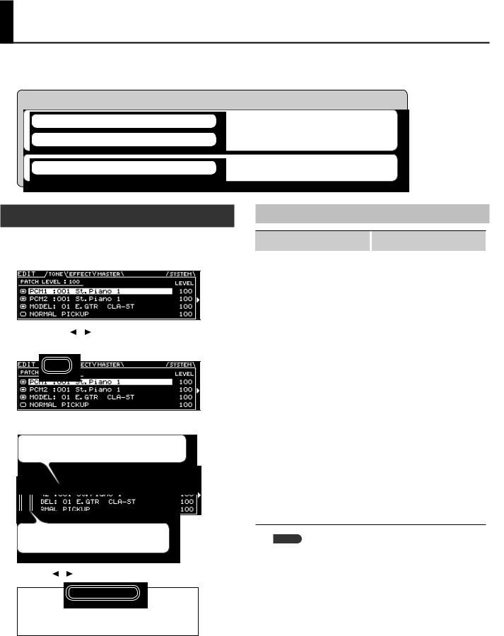
Editing the Tones (TONE)
As shown in the illustration below, a GR-55 patch consists of several tones.
You can create a new patch by selecting different tones or by editing the detailed settings of each tone.
PATCH
PCM TONE 1
PCM TONE 2
MODELING TONE
Synthesizer sound
This is a synthesizer sound that plays according to the performance data from your guitar. Two tones can be layered.
Modeling sound
This is a modeled sound based on the audio from each guitar string.
Changing the Tone
Here’s how to create a new sound by changing the tone that’s selected.
1.Press the [EDIT] button to access the EDIT screen..
2. Use the PAGE [ ] [ ] buttons to access the TONE tab..
The screen shows the structure of the currently selected patch.
3.Select a different tone..
Use the cursor buttons to select the tone that you want to change, and use the dial to select a different tone.
Move the cursor to the tone switch, and turn the tone on
 /off
/off
 .
.
The available tones are listed as shown in the illustration. You can use the cursor [ ] [ ] buttons to select the tone category (p. 23).
4.Press the [ENTER] button..
5.When you’ve finished making settings, press the [EXIT] button..
6.If you want to keep your settings, save the patch (p.. 60)..
Tone Category
Tone category |
Number |
|
of tones |
||
|
||
|
|
|
Ac.Piano |
16 |
|
|
|
|
Pop Piano |
3 |
|
|
|
|
E.Grand Piano |
2 |
|
|
|
|
E.Piano1 |
25 |
|
|
|
|
E.Piano2 |
13 |
|
|
|
|
E.Organ |
32 |
|
|
|
|
Pipe Organ |
5 |
|
|
|
|
Reed Organ |
1 |
|
|
|
|
Harpsichord |
5 |
|
|
|
|
Clav |
8 |
|
Celesta |
1 |
|
|
|
|
Accordion |
6 |
|
|
|
|
Harmonica |
2 |
|
|
|
|
Bell |
21 |
|
|
|
|
Mallet |
22 |
|
|
|
|
Ac.Guitar |
18 |
|
|
|
|
E.Guitar |
18 |
|
|
|
|
Dist.Guitar |
11 |
|
|
|
|
Ac.Bass |
4 |
|
|
|
|
E.Bass |
14 |
|
|
|
|
Synth Bass |
87 |
|
|
|
|
Plucked/Stroke |
18 |
|
|
|
|
Solo Strings |
9 |
|
|
|
Tone category |
Number |
|
of tones |
||
|
||
|
|
|
Ensemble Strings |
22 |
|
|
|
|
Orchestral |
4 |
|
|
|
|
Solo Brass |
11 |
|
|
|
|
Ensemble Brass |
7 |
|
|
|
|
Wind |
7 |
|
|
|
|
Flute |
12 |
|
|
|
|
Sax |
7 |
|
|
|
|
Recorder |
4 |
|
|
|
|
Vox/Choir |
28 |
|
|
|
|
Scat |
2 |
|
Synth Lead |
123 |
|
|
|
|
Synth Brass |
40 |
|
|
|
|
Synth Pad/Strings |
84 |
|
|
|
|
Synth Bellpad |
17 |
|
|
|
|
Synth PolyKey |
45 |
|
|
|
|
Synth FX |
31 |
|
|
|
|
Synth Seq/Pop |
11 |
|
|
|
|
Pulsating |
32 |
|
|
|
|
Beat&Groove |
11 |
|
|
|
|
Hit |
7 |
|
|
|
|
Sound FX |
37 |
|
|
|
|
Percussion |
13 |
|
|
|
|
Drums |
14 |
|
|
|
MEMO
If you select the “Drums” tone category, there will be fewer editable parameters than those listed in this manual.
23
Editing the Tones (TONE)
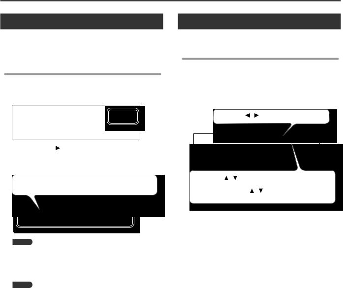
Editing the Tone
Here’s how to make various settings for the tone.
If you want to edit detailed settings, refer to “Editing a Tone (Detailed Settings)” (p. 24).
Basic operation
1.In step 3 of “Changing the Tone” (p.. 23), move the cursor to the TONE LEVEL field..
You can use the dial to edit the volume of the tone.
2. Press the cursor [ ] button..
The screen shows the parameters that can be edited for each tone.
3.Edit the parameter settings..
Use the cursor buttons to select the tone parameter that you want to edit, and use the dial to edit the value.
MEMO
This screen shows the parameters that are marked by a “#” symbol in the parameter list (p. 25 –). The parameters that you can edit will differ for each tone.
4.When you’ve finished editing, press the [EXIT] button..
5.If you want to keep your settings, save the patch (p.. 60)..
MEMO
If you want to adjust the overall volume of the patch, use the cursor buttons to select the PATCH LEVEL field, and use the dial to edit the value.
Value: 0–200
Editing a Tone (Detailed Settings)
Here’s how to edit the tone settings in detail.
Basic operation
1.In step 3 of “Changing the Tone” (p.. 23), select the tone that you want to edit..
2.Press the [ENTER] button..
The TONE EDIT screen will appear.
3.Edit the parameter settings..
Use the PAGE ] ] buttons to switch between tabs.
Use the cursor |
] |
] buttons to select the parameter that you want |
||
to edit, and use the dial to edit the value of the parameter. |
||||
By holding down the cursor |
] |
] buttons simultaneously you can |
||
make the cursor move faster. |
|
|
||
For details on each parameter, refer to “Parameter List (PCM TONE 1/ PCM TONE 2)” (p. 25).
4.When you’ve finished editing, press the [EXIT] button..
5.If you want to keep the changes you made, save the patch (p.. 60)..
24
Editing the Tones (TONE)
Parameter List (PCM TONE 1/PCM TONE 2)
Group |
Parameter |
Value |
Description |
|||||||||||||||
|
|
|
|
|
|
|
|
|
|
|
|
|
|
|
|
|
|
|
|
SWITCH |
OFF, ON |
Turns the tone on/off. |
|||||||||||||||
|
Tones that are turned “OFF” will not sound (they are muted). |
|||||||||||||||||
|
|
|
||||||||||||||||
|
|
|
|
|
|
|
|
|
|
|
|
|
|
|
|
|
|
|
|
TONE CATEGORY |
Selects the category (group) of tones. |
||||||||||||||||
|
|
|
|
|
|
|
|
|
|
|
|
|
|
|
|
|
|
|
|
TONE NUMBER |
Selects the tone number. |
|
|
|
|
|
|
|
|
|
|
|
|
|
|
|
|
|
|
|
|
|
|
|
|
|
|
|
|
|
|
|
|
|
|
|
|
LEVEL |
0–100 |
Adjusts the volume of the tone. |
|||||||||||||||
|
|
|
|
|
|
|
|
|
|
|
|
|
|
|
|
|
|
|
|
OCTAVE # |
-3–+3 |
Shifts the tone’s pitch in steps of an octave. |
|||||||||||||||
|
|
|
|
|
|
|
|
|
|
|
|
|
|
|
|
|
|
|
|
CHROMATIC |
OFF, ON |
Turn this “ON” if you want the tone to sound in chromatic steps. |
|||||||||||||||
|
If this is “ON,” the pitch will change only in semitone steps even if you “bend” a string. |
|||||||||||||||||
|
|
|
||||||||||||||||
|
|
|
|
|
|
|
|
|
|
|
|
|
|
|
|
|
|
|
|
|
OFF |
Turns the Legato function off. |
|||||||||||||||
|
|
|
|
|
|
|
|
|
|
|
|
|
|
|
|
|
|
|
|
LEGATO |
|
When you play notes in a smoothly connected manner by hammering-on or pulling- |
|||||||||||||||
|
ON |
off, only the pitch will change, and no attack will be heard for the subsequently played |
||||||||||||||||
|
|
note. |
||||||||||||||||
|
|
|
||||||||||||||||
|
|
|
The legato function can be used if CHROMATIC is ON. |
|||||||||||||||
|
|
|
|
|
|
|
|
|
|
|
|
|
|
|
|
|
|
|
TONE |
|
|
Adjusts the amount by which the tone’s volume will be affected by your playing |
|||||||||||||||
LEVEL VELOCITY SENS |
-50–+50 |
strength. |
||||||||||||||||
|
||||||||||||||||||
|
|
|
With positive “+” values, the volume will increase as you play more strongly. |
|||||||||||||||
|
|
|
|
|
|
|
|
|
|
|
|
|
|
|
|
|
|
|
|
|
|
Specifies the curve by which your playing strength will affect the tone’s volume. |
|||||||||||||||
|
|
|
Normally, you should choose “TONE.”The optimal curve for each tone will be used. |
|||||||||||||||
|
|
|
If you don’t want the tone’s volume to change, choose “FIX.” |
|||||||||||||||
|
VELOCITY CURVE TYPE |
FIX, 1–7, TONE |
|
|
|
|
|
|
|
|
|
|
|
|
|
|
|
|
|
|
|
|
|
|
|
|
|
|
|
|
|
|
|
|
|
|
|
|
|
|
1 |
2 |
3 |
4 |
5 |
6 |
7 |
|
|
|
|
||||||
|
NUANCE SW |
OFF, ON |
Specifies whether nuances of your performance (p. 28) will produce tonal change. |
||||||
|
|
|
|
|
|
|
|
|
|
|
PAN |
L50–R50 |
Specifies the pan setting. |
|
|
|
|
|
|
|
|
|
Adjusts the volume of each string. |
|
|
|
|
||
|
STRING LEVEL1–6 |
1–100 |
For the PCM1, PCM2, and MODELING tones, you can specify a value of “0” for each |
||||||
|
string that you don’t want to be sounded for that tone; this allows you to create “split” |
||||||||
|
|
|
|||||||
|
|
|
setups. |
|
|
|
|
|
|
|
|
|
|
|
|
||||
|
PITCH SHIFT |
-24–+24 |
Specifies the tone’s pitch (semitone steps, +/-2 octaves). |
|
|
||||
|
|
|
|
|
|||||
|
PITCH FINE |
-50–+50 |
Specifies the tone’s pitch (in one cent steps; equivalent to 1/100 semitone). |
|
|||||
|
|
|
|
|
|
|
|
||
|
|
OFF |
Portamento will not be applied. |
|
|
|
|
||
|
PORTAMENTO SW |
|
|
|
|
|
|
|
|
|
ON |
Portamento will be applied. |
|
|
|
|
|
||
|
|
|
|
|
|||||
PITCH |
TONE |
The setting most appropriate for the tone will be used. |
|
|
|||||
|
|
RATE |
The time required for the pitch change is proportionate to the amount of pitch |
||||||
|
|
change. |
|
|
|
|
|
|
|
|
PORTAMENTO TYPE |
|
|
|
|
|
|
|
|
|
TIME |
The pitch change will occupy the same length of time regardless of the amount of |
|||||||
|
|
||||||||
|
|
pitch change. |
|
|
|
|
|
|
|
|
|
|
|
|
|
|
|
|
|
|
|
|
|
|
|||||
|
PORTAMENTO TIME |
0–100 |
Specifies the time required for the pitch change when using portamento. |
|
|||||
25
Editing the Tones (TONE)
Group |
Parameter |
Value |
Description |
||||||||||||||
|
|
|
|
|
|
|
|
|
|
|
|
|
|
|
|
|
|
|
|
OFF |
The filter will not be used. |
||||||||||||||
|
|
|
|
|
|
|
|
|
|
|
|
|
|
|
|
|
|
|
|
LPF |
Low Pass Filter. |
||||||||||||||
|
|
The region above the cutoff frequency will be cut, making the sound more mellow. |
|||||||||||||||
|
|
|
|||||||||||||||
|
|
|
Band Pass Filter. |
||||||||||||||
|
|
BPF |
The region around the cutoff frequency will remain, and the regions above and below |
||||||||||||||
|
|
|
will be cut. This is a useful way to create a distinctive sound. |
||||||||||||||
|
|
|
|
|
|
|
|
|
|
|
|
|
|
|
|
|
|
|
|
|
High Pass Filter. |
||||||||||||||
|
|
HPF |
The region below the cutoff frequency will be cut. This is appropriate for percussive |
||||||||||||||
|
|
|
sounds with a distinctive high-frequency component. |
||||||||||||||
|
|
|
|
|
|
|
|
|
|
|
|
|
|
|
|
|
|
|
|
|
Peaking Filter. |
||||||||||||||
|
|
PKG |
The region around the cutoff frequency will be emphasized. You can produce a wah |
||||||||||||||
|
FILTER TYPE |
|
effect by using an LFO to cyclically change the cutoff frequency. |
||||||||||||||
|
|
|
Low Pass Filter 2. |
||||||||||||||
|
|
LPF2 |
The region above the cutoff frequency will be cut, but the filter sensitivity will be half |
||||||||||||||
|
|
that of LPF. This is suitable for simulating instruments such as acoustic piano. |
|||||||||||||||
|
|
|
|||||||||||||||
|
|
|
* If “LPF2” is selected, the RESONANCE setting will be unavailable.. |
||||||||||||||
|
|
|
|
|
|
|
|
|
|
|
|
|
|
|
|
|
|
|
|
|
Low Pass Filter 3. |
||||||||||||||
|
|
|
The region above the cutoff frequency will be cut, but the filter sensitivity will change |
||||||||||||||
|
|
LPF3 |
according to the cutoff frequency. This is suitable for simulating acoustic instruments, |
||||||||||||||
|
|
but even with the same TVF ENVELOPE settings, it will produce a sound with a |
|||||||||||||||
FILTER |
|
|
|||||||||||||||
|
|
different nuance than LPF2. |
|||||||||||||||
|
|
|
* If “LPF3” is selected, the RESONANCE setting will be unavailable.. |
||||||||||||||
|
|
|
|
|
|
|
|
|
|
|
|
|
|
|
|
|
|
|
|
TONE |
The setting most appropriate for the tone will be used. |
||||||||||||||
|
|
|
|
|
|
|
|
|
|
|
|
|
|
|
|
|
|
|
CUTOFF # |
-50–+50 |
Specifies the frequency at which the filter will begin to be applied. |
||||||||||||||
|
|
|
|
|
|
|
|
|
|
|
|
|
|
|
|
|
|
|
RESONANCE |
-50–+50 |
Boosts the region near the cutoff frequency, giving the sound a distinctive character. |
||||||||||||||
|
Raising this value excessively may cause oscillation and distortion. |
||||||||||||||||
|
|
|
|||||||||||||||
|
|
|
|
|
|
|
|
|
|
|
|
|
|
|
|
|
|
|
CUTOFF VELOCITY SENS |
-50–+50 |
Specifies the amount by which your playing strength will vary the cutoff frequency. |
||||||||||||||
|
With positive “+” values, stronger playing will raise the cutoff frequency. |
||||||||||||||||
|
|
|
|||||||||||||||
|
|
|
|
|
|
|
|
|
|
|
|
|
|
|
|
|
|
|
CUTOFF NUANCE SENS |
-50–+50 |
Specifies how nuances of your performance (p. 28) will affect the filter cutoff frequency. |
||||||||||||||
|
|
|
|
|
|
|
|
|
|
|
|
|
|
|
|
|
|
|
|
|
Specifies the curve by which your playing strength will affect the cutoff frequency. |
||||||||||||||
|
|
|
Normally, you should choose “TONE.”The optimal curve for each tone will be used. |
||||||||||||||
|
|
FIX, |
If you don’t want the cutoff frequency to be affected, choose “FIX.” |
||||||||||||||
|
CUTOFF VELOCITY CURVE |
|
|
|
|
|
|
|
|
|
|
|
|
|
|
|
|
|
1–7, |
|
|
|
|
|
|
|
|
|
|
|
|
|
|
|
|
|
|
TONE |
|
|
|
|
|
|
|
|
|
|
|
|
|
|
|
|
|
|
|
|
|
|
|
|
|
|
|
|
|
|
|
|
|
|
|
|
1 |
2 |
3 |
4 |
5 |
6 |
7 |
|
|
|
|
|
|||||
|
CUTOFF KEYFOLLOW |
-200–+200 |
Specifies how the pitch of the note you play will affect the cutoff frequency. |
|
|||||
|
With positive “+” values, the cutoff frequency will rise as you player higher notes. |
||||||||
|
|
|
|||||||
|
|
|
|
|
|
|
|
||
|
TVF ENV DEPTH |
-50–+50 |
Adjusts the depth of the TVF envelope. |
|
|
|
|
||
|
Higher values will increase the change produced by the TVF envelope. |
|
|||||||
|
|
|
|
||||||
|
|
|
|
|
|
|
|||
|
TVF ATTACK TIME |
-50–+50 |
Adjusts the attack time of the filter envelope. |
|
|
|
|||
|
|
|
|
|
|
|
|||
|
TVF DECAY TIME |
-50–+50 |
Adjusts the decay time of the filter envelope. |
|
|
|
|||
TVF |
|
|
|
|
|
|
|||
TVF SUSTAIN LEVEL |
-50–+50 |
Adjusts the sustain level of the filter envelope. |
|
|
|
||||
|
|
|
|
|
|
|
|||
|
TVF RELEASE TIME |
-50–+50 |
Adjusts the release time of the filter envelope. |
|
|
|
|||
|
|
|
|
|
|||||
|
TVF ATTACK VEL SENS |
-50–+50 |
Specifies how your playing strength will affect the filter attack time. |
|
|||||
|
With positive “+” values, stronger playing will shorten the attack time. |
|
|||||||
|
|
|
|
||||||
|
TVF ATK NUANCE SENS |
-50–+50 |
Specifies how nuances of your performance (p. 28) will affect the filter attack time. |
||||||
26
Editing the Tones (TONE)
Group |
Parameter |
Value |
|
|
|
|
|
|
|
|
|
Description |
||
|
|
|
|
|
|
|
|
|
|
|
|
|
||
|
TVA ATTACK TIME # |
-50–+50 |
Adjusts the attack time of the amp envelope. |
|||||||||||
|
|
|
|
|
|
|
|
|
|
|
|
|
||
|
TVA DECAY TIME |
-50–+50 |
Adjusts the decay time of the amp envelope. |
|||||||||||
|
|
|
|
|
|
|
|
|
|
|
|
|
||
|
TVA SUSTAIN LEVEL |
-50–+50 |
Adjusts the sustain level of the amp envelope. |
|||||||||||
|
|
|
|
|
|
|
|
|
|
|
|
|
||
|
TVA RELEASE TIME # |
-50–+50 |
Adjusts the release time of the amp envelope. |
|||||||||||
|
|
|
|
|
|
|
|
|
|
|
|
|
|
|
|
TVA ATTACK VEL SENS |
-50–+50 |
Specifies how your playing strength will affect the attack time. |
|||||||||||
TVA |
With positive “+” values, stronger playing will shorten the attack time. |
|||||||||||||
|
|
|
|
|
|
|
|
|
|
|
|
|||
|
|
|
|
|
|
|
|
|
|
|
|
|
||
|
TVA ATK NUANCE SENS |
-50–+50 |
Specifies how nuances of your performance (p. 28) will affect the attack time of the level. |
|||||||||||
|
|
|
|
|
|
|
|
|
|
|
|
|
||
|
LEVEL NUANCE SENS |
-50–+50 |
Specifies how nuances of your performance (p. 28) will affect the volume. |
|||||||||||
|
|
|
|
|
|
|
|
|
|
|
|
|
|
|
|
|
1 |
|
|
|
|
|
|
|
|
|
|
The next note will be sounded while maintaining the release of a previously played |
|
|
|
|
|
|
|
|
|
|
|
|
|
note sounding on the same string. |
||
|
RELEASE MODE |
|
|
|
|
|
|
|
|
|
|
|
||
|
|
|
|
|
|
|
|
|
|
|
|
|
||
|
2 |
|
|
|
|
|
|
|
|
|
|
Any previously played note sounding on the same string will be forcibly decayed |
||
|
|
|
|
|
|
|
|
|
|
|
|
|||
|
|
|
|
|
|
|
|
|
|
|
|
before the next note is sounded. |
||
|
|
|
|
|
|
|
|
|
|
|
|
|
||
|
|
|
|
|
|
|
|
|
|
|
|
|
|
|
|
|
|
|
|
|
|
|
|
|
|
|
|
Specifies how your playing strength will affect the depth of the pitch envelope. |
|
|
PITCH ENV VEL SENS |
-50–+50 |
With positive “+” values, stronger playing will increase the change produced by the |
|||||||||||
|
|
|
|
|
|
|
|
|
|
|
|
|
pitch envelope. |
|
|
|
|
|
|
|
|
|
|
|
|
|
|
|
|
PITCH ENV |
PITCH ENV DEPTH |
-12–+12 |
Adjusts the depth of the pitch envelope. |
|||||||||||
|
Higher settings will increase the change produced by the pitch envelope. |
|||||||||||||
|
|
|
|
|
|
|
|
|
|
|
|
|
||
|
|
|
|
|
|
|
|
|
|
|
|
|
||
|
PITCH ATTACK TIME |
-50–+50 |
Adjusts the attack time of the pitch envelope. |
|||||||||||
|
|
|
|
|
|
|
|
|
|
|
|
|
||
|
PITCH DECAY TIME |
-50–+50 |
Adjusts the decay time of the pitch envelope. |
|||||||||||
|
|
|
|
|
|
|
|
|
|
|
|
|
|
|
|
|
0–100 |
|
|
|
|
|
|
|
|
|
Specifies the LFO rate (speed). |
||
|
LFO1 RATE |
BPM |
|
– |
|
|
|
|
|
|
|
|
Makes the LFO rate synchronize to the tempo in units of the note value you specify. |
|
|
|
|
|
|
|
|||||||||
|
|
|
|
|
|
|
|
|
|
|
|
|
|
|
|
|
TONE |
|
|
|
|
|
|
|
|
|
The LFO rate will be set appropriately for the tone. |
||
|
|
|
|
|
|
|
|
|
|
|
|
|
|
|
|
LFO1 PITCH DEPTH |
OFF, -50–+50 |
Specifies how the LFO will affect the pitch. |
|||||||||||
|
Choose “OFF” if you don’t want the LFO to affect the pitch. |
|||||||||||||
|
|
|
|
|
|
|
|
|
|
|
|
|
||
LFO1 |
|
|
|
|
|
|
|
|
|
|
|
|
|
|
LFO1 TVF DEPTH |
OFF, -50–+50 |
Specifies how the LFO will affect the cutoff frequency. |
||||||||||||
|
||||||||||||||
|
Choose “OFF” if you don’t want the LFO to affect the TVF. |
|||||||||||||
|
|
|
|
|
|
|
|
|
|
|
|
|
||
|
|
|
|
|
|
|
|
|
|
|
|
|
|
|
|
LFO1 TVA DEPTH |
OFF, -50–+50 |
Specifies how the LFO will affect the volume. |
|||||||||||
|
Choose “OFF” if you don’t want the LFO to affect the TVA. |
|||||||||||||
|
|
|
|
|
|
|
|
|
|
|
|
|
||
|
|
|
|
|
|
|
|
|
|
|
|
|
|
|
|
LFO1 PAN DEPTH |
OFF, -50–+50 |
Specifies how the LFO will affect pan (stereo position). |
|||||||||||
|
Choose “OFF” if you don’t want the LFO to affect pan. |
|||||||||||||
|
|
|
|
|
|
|
|
|
|
|
|
|
||
|
|
|
|
|
|
|
|
|
|
|
|
|
|
|
|
|
0–100 |
|
|
|
|
|
|
|
|
|
Specifies the LFO rate (speed). |
||
|
LFO2 RATE |
|
|
|
|
|
|
|
|
|
|
|
|
|
|
BPM |
|
– |
|
|
|
|
|
|
|
|
Makes the LFO rate synchronize to the tempo in units of the note value you specify. |
||
|
|
|
|
|
|
|||||||||
|
|
|
|
|
|
|
|
|
|
|
|
|
|
|
|
|
TONE |
|
|
|
|
|
|
|
|
|
The LFO rate will be set appropriately for the tone. |
||
|
|
|
|
|
|
|
|
|
|
|
|
|
|
|
|
LFO2 PITCH DEPTH |
OFF, -50–+50 |
Specifies how the LFO will affect the pitch. |
|||||||||||
|
Choose “OFF” if you don’t want the LFO to affect the pitch. |
|||||||||||||
|
|
|
|
|
|
|
|
|
|
|
|
|
||
LFO2 |
|
|
|
|
|
|
|
|
|
|
|
|
|
|
LFO2 TVF DEPTH |
OFF, -50–+50 |
Specifies how the LFO will affect the cutoff frequency. |
||||||||||||
|
||||||||||||||
|
Choose “OFF” if you don’t want the LFO to affect the TVF. |
|||||||||||||
|
|
|
|
|
|
|
|
|
|
|
|
|
||
|
|
|
|
|
|
|
|
|
|
|
|
|
|
|
|
LFO2 TVA DEPTH |
OFF, -50–+50 |
Specifies how the LFO will affect the volume. |
|||||||||||
|
Choose “OFF” if you don’t want the LFO to affect the TVA. |
|||||||||||||
|
|
|
|
|
|
|
|
|
|
|
|
|
||
|
|
|
|
|
|
|
|
|
|
|
|
|
|
|
|
LFO2 PAN DEPTH |
OFF, -50–+50 |
Specifies how the LFO will affect pan (stereo position). |
|||||||||||
|
Choose “OFF” if you don’t want the LFO to affect pan. |
|||||||||||||
|
|
|
|
|
|
|
|
|
|
|
|
|
||
27

Editing the Tones (TONE)
Using the Nuance parameters
The Nuance parameters detect when you play your guitar/bass with a soft touch, and apply a corresponding change to the sound of the PCM tone.
For example, if CUTOFF NUANCE SENS is set to a positive “+” value, the cutoff frequency of the PCM tone will be lowered when you play a muted or a finger-picked note, producing a softer tone quality.
As another example, you might use PCM TONE 1 to create the sound that will be heard when you pluck the string with a pick, and PCM TONE 2 to create the sound that will be heard when you pluck the string with your finger. Then set the Nuance parameters as follows, allowing you to switch between PCM TONE 1 and 2 by alternating your performance technique.
•PCM TONE 1 settings
TONE CATEGORY/NUMBER: the tone sounded for a note played with a pick LEVEL NUANCE SENS: +50
•PCM TONE 2 settings
TONE CATEGORY/NUMBER: the tone sounded for a note played with your finger LEVEL NUANCE SENS: -50
To enable the Nuance parameters, turn NUANCE SW “ON” and adjust each NUANCE SENS parameter as desired.
If you want to adjust the nuance so it’s appropriate for the guitar or bass you’re using, set the SYSTEM - GK SETTING parameters NUANCE DYNAMICS and NUANCE TRIM (p. 75).
28

|
|
|
|
|
|
Editing the Tones (TONE) |
|
|
|
|
|
|
|
Parameter List (MODELING TONE) |
|
|
|
|||
|
|
|
|
|
|
|
|
Group |
Parameter |
Value |
Description |
|
|
|
|
|
|
|
|
|
|
|
SWITCH |
OFF, ON |
Turns the tone on/off. Tones turned “OFF” will not sound (i.e., they are muted). |
||
|
|
|
|
|
|
|
|
|
|
If GUITAR<->BASS is set to “GUITAR” (p. 9) |
|
|
|
|
|
|
|
|
|
|
|
|
|
E.GTR, |
|
|
|
|
|
|
AC, |
Selects the category (group) of tones. |
|
|
|
|
|
E.BASS, |
|
|
|
|
|
|
|
|
|
|
|
|
TONE CATEGORY |
SYNTH |
|
|
|
|
|
|
If GUITAR<->BASS is set to “BASS” (p. 9) |
|
|
|
|
|
|
|
|
|
|
|
TONE |
|
E.BASS, |
|
|
|
|
|
SYNTH, |
Selects the category (group) of tones. |
|
|
|
|
|
|
|
|
||
|
|
|
E.GTR |
|
|
|
|
|
TONE NUMBER |
001– |
Selects the tone. For an explanation, refer to the following table (TONE CATEGORY: |
||
|
|
E.GTR–SYNTH). |
|
|
||
|
|
|
|
|
|
|
|
|
|
|
|
|
|
|
|
LEVEL |
0–100 |
Adjusts the volume of the tone. |
|
|
|
|
|
|
Adjusts the volume of each string. |
|
|
|
|
STRING LEVEL1–6 |
0–100 |
For the PCM1, PCM2, and MODELING tones, you can specify a value of “0” for each |
||
|
|
string that you don’t want to be sounded for that tone; this allows you to create “split” |
||||
|
|
|
|
|||
|
|
|
|
setups. |
|
|
|
|
|
|
|
|
|
|
PITCH |
PITCH SHIFT |
-24–+24 |
Adjusts the pitch of the tone (in semitone steps, +/-2 octaves). |
||
|
|
|
|
|
|
|
|
PITCH FINE |
-50–+50 |
Adjusts the pitch of the tone (in one cent steps; equivalent to 1/100 semitone). |
|||
|
|
|||||
|
|
|
|
|
|
|
|
|
12STR SW |
|
Turn this on if you want to produce the sound of a 12-string guitar. The sound of a |
||
|
|
OFF/ON |
conventional 6-string guitar will be transformed to the sound of a 12-string guitar |
|||
|
|
|
|
with its supplementary strings. |
|
|
|
|
|
|
|
|
|
|
|
DIRECT LEVEL |
0–100 |
Specifies the volume of the main strings. |
|
|
|
|
|
|
|
|
|
|
|
|
|
Adjusts the pitch difference of each |
* |
On a conventional 12-string guitar, |
|
|
SHIFT1–6 |
-24–+24 |
supplementary string relative to |
|
supplementary strings 1 and 2 are tuned |
|
|
the corresponding main string, in |
|
to the same pitch (SHIFT = 0) as the corre- |
||
|
|
|
|
|
||
|
|
|
|
semitone steps. |
|
sponding main string, and supplementary |
|
|
|
|
|
|
strings 3–6 are tuned one octave higher |
|
|
|
|
Adjusts the pitch of each |
|
(SHIFT = +12) than the corresponding |
|
12STR |
FINE1–6 |
-50–+50 |
supplementary string in cents |
|
main string.. Slightly raising each string’s |
|
|
|
|
(1/100 semitone steps). |
|
FINE setting will produce a more realistic |
|
|
|
|
|
|
12-string guitar tone.. |
|
|
|
|
|
|
|
*12STR cannot be used with any of the following settings (the parameters will not be shown)..
•MODELING TONE parameters
TONE CATEGORY=E.BASS (if set to GUITAR input) or E.GTR (if set to BASS input) PITCH SHIFT≠0
PITCH FINE≠0
•MASTER parameters
ALTERNATE TUNING “SWITCH” =ON
29

Editing the Tones (TONE)
*Company names and product names appearing in this document are the registered trademarks or trademarks of their respective owners.. This document uses these names in order to appropriately describe the sounds simulated by COSM technology..
TONE CATEGORY: E.GTR |
|
||
|
|
|
|
|
TONE NUMBER (PICKUP) |
Description |
|
|
|
|
|
|
GUITAR |
BASS |
|
|
|
||
|
|
|
|
|
01: CLA-ST |
16: ST |
This models a Fender Stratocaster, a guitar with three traditional single-coil pickups. |
|
|
|
|
|
02: MOD-ST |
— |
This models a guitar with three EMG active single-coil pickups. |
|
|
|
|
|
03: H&H-ST |
— |
This models a Stratocaster-type guitar with humbucking pickups. |
|
|
|
|
|
04: TE |
— |
This models a Fender Telecaster, a guitar with two single-coil pickups often used in blues and country music. |
|
|
|
|
|
05: LP |
17: LP |
This models a Gibson Les Paul Standard, a guitar with two humbucking pickups often used in rock. |
|
|
|
|
|
06: P-90 |
— |
This models a Gibson Les Paul Junior, a guitar with two single-coil pickups affectionately referred to as “dog ear” or “soap bar” |
|
pickups. |
||
|
|
|
|
|
|
|
|
|
07: LIPS |
— |
This models a Danelectro 56-U3, a guitar with three pickups with a distinctive silver “lipstick-style” appearance. |
|
|
|
|
|
08: RICK |
— |
This models a Rickenbacker 360, a semi-hollow body guitar with two unique single-coil pickups. |
|
|
|
|
09: 335 |
— |
This models a Gibson ES-335 Dot, a well-known semi-acoustic guitar with two humbucking pickups. |
|
|
|
|
|
|
10: L4 |
— |
This models a Gibson L-4 CES, a acoustic-body guitar suitable for jazz, equipped with two humbucking pickups and strung with |
|
flat-wound strings. |
||
|
|
|
|
|
|
|
|
TONE CATEGORY: E.BASS |
|
||
|
|
|
|
|
TONE NUMBER (PICKUP) |
Description |
|
|
|
|
|
|
GUITAR |
BASS |
|
|
|
||
|
— |
01: VINT JB |
This models a Fender Jazz Bass made in the 1960s. |
|
|
|
|
|
16: JB |
02: JB |
This models a Fender Jazz Bass. |
|
|
|
|
|
— |
03: VINT PB |
This models a Fender Precision Bass made in the early 1960s. |
|
|
|
|
|
17: PB |
04: PB |
This models a Fender Precision Bass. |
|
|
|
|
|
— |
05: M-MAN |
This models a Music Man StingRay Bass made in the 1970s. |
|
|
|
|
|
— |
06: RICK |
This models a Rickenbacker 4001. |
|
|
|
|
|
— |
07: T-BIRD |
This models a Gibson Thunderbird. |
|
|
|
|
|
— |
08: ACTIVE |
This models a typical bass equipped with active pickups. |
|
|
|
|
|
— |
09: VIOLIN |
This models a Höfner violin bass. |
|
|
|
|
TONE CATEGORY: AC |
|
||
|
|
|
|
|
TONE NUMBER (PICKUP) |
Description |
|
|
|
|
|
|
GUITAR |
BASS |
|
|
|
||
|
11: STEEL |
— |
This models a steel-string guitar. |
|
|
|
|
|
12: NYLON |
— |
This models a nylon-string guitar. |
|
|
|
|
|
13: SITAR |
— |
This models a Coral electric sitar. The sitar’s distinctive buzz and tonal change are modeled. |
|
|
|
|
|
14: BANJO |
— |
This models a conventional five-string banjo. |
|
|
|
|
|
15: RESO |
— |
This models a Dobro-type resonator guitar. |
|
|
|
|
30
Loading...