


 Loading...
N∫m-Û.,,
ORDER NO.
RRV2599
VSX-D511-K
AUDIO/VIDEO MULTI-CHANNEL RECEIVER
VSX-D511-K
VSX-D511-S
THIS MANUAL IS APPLICABLE TO THE FOLLOWING MODEL(S) AND TYPE(S).
Model |
Type |
Power Requirement |
Remarks |
|
|
|
|
VSX-D511-K |
MVXJI |
AC230V |
|
|
|
|
|
VSX-D511-S |
MYXJIEW |
AC220-230V |
|
|
|
|
|
VSX-D511-K |
MYXJIEW |
AC220-230V |
|
|
|
|
|
VSX-D511-K |
MYXJIGR |
AC220-230V |
|
|
|
|
|
For details, refer to "Important symbols for good services" on the next page.
PIONEER CORPORATION 4-1, Meguro 1-chome, Meguro-ku, Tokyo 153-8654, Japan
PIONEER ELECTRONICS (USA) INC. P.O. Box 1760, Long Beach, CA 90801-1760, U.S.A.
PIONEER EUROPE NV Haven 1087, Keetberglaan 1, 9120 Melsele, Belgium
PIONEER ELECTRONICS ASIACENTRE PTE. LTD. 253 Alexandra Road, #04-01, Singapore 159936
 PIONEER CORPORATION 2002
T-ZZR APR.2002.printed in Japan
1 |
2 |
3 |
4 |
SAFTY INFORMATION
A
This service manual is intended for qualified service technicians; it is not meant for the casual do-it-yourselfer. Qualified technicians have the necessary test equipment and tools, and have been trained to properly and safely repair complex products such as those covered by this manual.
Improperly performed repairs can adversely affect the safety and reliability of the product and may void the warranty. If you are not qualified to perform the repair of this product properly and safely, you should not risk trying to do so and refer the repair to a qualified service technician.
WARNING
BThis product contains lead in solder and certain electrical parts contain chemicals which are known to the state of California to cause cancer, birth defects or other reproductive harm.
Health & Safety Code Section 25249.6 – Proposition 65
NOTICE
(FOR CANADIAN MODEL ONLY)
Fuse symbols  (fast operating fuse) and/or
  (slow operating fuse) on PCB indicate that replacement parts must be of identical designation.
REMARQUE
(POUR MODÈLE CANADIEN SEULEMENT)
C Les symboles de fusible  (fusible de type rapide) et/ou
  (fusible de type lent) sur CCI indiquent que les pièces de remplacement doivent avoir la même désignation.
(FOR USA MODEL ONLY)
1. SAFETY PRECAUTIONS
The following check should be performed for the continued protection of the customer and ser vice technician.
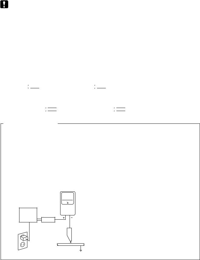
LEAKAGE CURRENT CHECK
Measure leakage current to a known earth ground (water pipe, conduit, etc.) by connecting a leakage
Dcurrent tester such as Simpson Model 229 - 2 or equivalent between the earth ground and all exposed metal parts of the appliance (input/output terminals, screwheads, metal overlays, control shaft, etc.). Plug the AC line cord of the appliance directly into a 120V AC 60 Hz outlet and turn the AC power switch on. Any current measured must not exceed 0.5 mA.
|
|
|
Reading should |
|
|
Leakage |
not be above |
|
|
0.5 mA |
|
|
|
current |
|
|
|
|
|
E |
Device |
tester |
|
under |
|
|
|
|
|
|
|
|
test |
|
|
|
Test all |
|
|
|
exposed metal |
|
|
|
surfaces |
|
|
|
Also test with |
|
|
|
plug reversed |
|
|
|
(Using AC adapter |
|
Earth |
|
plug as required) |
|
ground |
AC Leakage Test
ANY MEASUREMENTS NOT WITHIN THE LIMITS OUTLINED ABOVE ARE INDICATIVE OF A POTENTIAL SHOCK HAZARD AND MUST BE CORRECTED BEFORE RETURNING THE APPLIANCE TO THE CUSTOMER.
2. PRODUCT SAFETY NOTICE
Many electrical and mechanical parts in the appliance have special safety related characteristics. These are often not evident from visual inspection nor the protection afforded by them necessarily can be obtained by using replacement components rated for voltage, wattage, etc. Replacement par ts which have these special safety characteristics are identified in this Service Manual.
Electrical components having such features are identified by marking with a  on the schematics and on the parts list in this Service Manual.
The use of a substitute replacement component which does not have the same safety characteristics as the PIONEER recommended replacement one, shown in the parts list in this Service Manual, may create shock, fire, or other hazards.
Product Safety is continuously under review and new instructions are issued from time to time. For the latest information, always consult the current PIONEER Service Manual. A subscription to, or additional copies of, PIONEER Service Manual may be obtained at a nominal charge from PIONEER.
F
2 |
|
VSX-D511-K |
|
|
1 |
2 |
|
3 |
4 |

5 |
6 |
7 |
8 |
[ Important symbols for good services ]
In this manual, the symbols shown-below indicate that adjustments, settings or cleaning should be made securely. When you find the procedures bearing any of the symbols, be sure to fulfill them:
1. Product safety
You should conform to the regulations governing the product (safety, radio and noise, and other regulations), and should keep the safety during servicing by following the safety instructions described in this manual.
2. Adjustments
To keep the original performances of the product, optimum adjustments or specification confirmation is indispensable. In accordance with the procedures or instructions described in this manual, adjustments should be performed.
3. Cleaning
For optical pickups, tape-deck heads, lenses and mirrors used in projection monitors, and other parts requiring cleaning, proper cleaning should be performed to restore their performances.
4. Shipping mode and shipping screws
To protect the product from damages or failures that may be caused during transit, the shipping mode should be set or the shipping screws should be installed before shipping out in accordance with this manual, if necessary.
5. Lubricants, glues, and replacement parts
Appropriately applying grease or glue can maintain the product performances. But improper lubrication or applying
 glue may lead to failures or troubles in the product. By following the instructions in this manual, be sure to apply the
 prescribed grease or glue to proper portions by the appropriate amount.For replacement parts or tools, the prescribed ones should be used.
A
B
C
D
E
F
|
|
|
|
|
|
|
|
|
VSX-D511-K |
7 |
3 |
||
5 |
6 |
|
|
|
8 |
|
1 2 3 4
CONTENTS
|
SAFTY INFORMATION . . . . . . . . . |
. . . . . . . . . . . . . . . . . . . . . . . . . . . . . . . . . . . . 2 |
||
A |
1. |
SPECIFICATIONS . . . . . . . . . . . |
. . . . . . . . . . . . . . . . . . . . . . . . . . . . . . . . . . . . 5 |
|
2. |
EXPLODED VIEWS AND PARTS LIST |
. . . . . . . . . . . . . . . . . . . . . . . . . . . . . . . . . . . . 6 |
||
|
||||
|
|
2.1 PACKING . . . . . . . . . . . . . |
. . . . . . . . . . . . . . . . . . . . . . . . . . . . . . . . . . . . 6 |
|
2.2EXTERIOR SECTION . . . . . . . . . . . . . . . . . . . . . . . . . . . . . . . . . . . . . . . . . . . 8
2.3FRONT PANEL SECTION . . . . . . . . . . . . . . . . . . . . . . . . . . . . . . . . . . . . . . . . 10
3.BLOCK DIAGRAM AND SCHEMATIC DIAGRAM . . . . . . . . . . . . . . . . . . . . . . . . . . . . . . 12
3.1BLOCK DIAGRAM . . . . . . . . . . . . . . . . . . . . . . . . . . . . . . . . . . . . . . . . . . . . 12
3.2OVERALL WIRING CONNECTION DIAGRAM . . . . . . . . . . . . . . . . . . . . . . . . . . . . . 14
3.3D.D & INPUT(1/4) ASSY . . . . . . . . . . . . . . . . . . . . . . . . . . . . . . . . . . . . . . . . . 16
3.4D.D & INPUT(2/4) ASSY . . . . . . . . . . . . . . . . . . . . . . . . . . . . . . . . . . . . . . . . . 18
B3.5 D.D & INPUT(3/4) ASSY . . . . . . . . . . . . . . . . . . . . . . . . . . . . . . . . . . . . . . . . . 20
3.6D.D & INPUT(4/4) ASSY . . . . . . . . . . . . . . . . . . . . . . . . . . . . . . . . . . . . . . . . . 22
3.7AMP & PRIMARY(1/2), TRANS2 and TRANS3 ASSYS . . . . . . . . . . . . . . . . . . . . . . . . . 24
3.8 AMP & PRIM.(2/2), REG., HASHIGETA, B TO B and MECH SW ASSYS |
. . . . . |
. . . . . |
. . . . |
. 26 |
3.9 VIDEO, 6CH IN and S.VIDEO ASSYS. . . . . . . . . . . . . . . . . . . |
. . . . . |
. . . . . |
. . . . |
. 28 |
3.10 |
FRONT, R.ENCODER and POWER SW ASSYS . . . . . . . . . . . . . . . . . . . . . . . . . . . 30 |
3.11 |
DIGITAL IN, H.P. and KAWA ASSYS . . . . . . . . . . . . . . . . . . . . . . . . . . . . . . . . . . 32 |
3.12 |
FM/AM TUNER MODULE . . . . . . . . . . . . . . . . . . . . . . . . . . . . . . . . . . . . . . . 34 |
4.PCB CONNECTION DIAGRAM . . . . . . . . . . . . . . . . . . . . . . . . . . . . . . . . . . . . . . . 36
4.1TRANS1, TRANS2 and TRANS3 ASSYS . . . . . . . . . . . . . . . . . . . . . . . . . . . . . . . . 37
C |
4.2 |
D.D & INPUT ASSY . . . . . . . . . . . . . . . . . . . . . . . . . . . . . . . . . . . . . . . . . . . 38 |
|
|
|||
|
4.3 |
AMP INPUT, AMP & PRIMARY and MECHA SW ASSYS. . . . . . . . . . . . . . . . . . . . . . . . 42 |
|
|
4.4 |
FRONT, POWER SW, H.P. and R.ENCODER ASSYS |
. . . . . . . . . . . . . . . . . . . . . . . . . 44 |
|
4.5 |
REGULATOR, HASHIGETA and KAWA ASSYS. . . . . . . . . . . . . . . . . . . . . . . . . . . . . 48 |
|
|
4.6 |
DIGITAL IN, 6CH IN, VIDEO and BOARRO TO BOARD ASSYS . . . . . . . . . . . . . . . . . . . . 50 |
|
|
4.7 |
FM/AM TUNER MODULE . . . . . . . . . . . . . . . . . . . . . . . . . . . . . . . . . . . . . . . . 52 |
|
5. |
PCB PARTS LIST . . . . . . . . . . . . . . . . . . . . . |
. . . . . . . . . . . . . . . . . . . . . . . . . 53 |
|
6. |
ADJUSTMENT . . . . . . . . . . . . . . . . . . . . . . . |
. . . . . . . . . . . . . . . . . . . . . . . . . 58 |
|
7. |
GENERAL INFORMATION . . . . . . . . . . . . . . . . . |
. . . . . . . . . . . . . . . . . . . . . . . . . 59 |
|
D7.1 DISASSEMBLY and DIAGNOSI . . . . . . . . . . . . . . . . . . . . . . . . . . . . . . . . . . . . . 59
7.1.1DISASSEMBLY and PCB LOCATION . . . . . . . . . . . . . . . . . . . . . . . . . . . . . . . . . 59
7.1.2U-COM BLOCKDIAGRAM . . . . . . . . . . . . . . . . . . . . . . . . . . . . . . . . . . . . . . . 60
7.1.3PROTECTION CIRCUIT . . . . . . . . . . . . . . . . . . . . . . . . . . . . . . . . . . . . . . . . 61
7.1.4POWER ON SEQUENCE . . . . . . . . . . . . . . . . . . . . . . . . . . . . . . . . . . . . . . . 62
7.1.5 POWER OFF SEQUENCE |
. . . . . . . . . . . . . . . . . . . . . . . . . . . . . . . . . . . . . . 63 |
|||||||
7.2 PARTS . . . . . . . . . . . . . . . . . . . . . . . . . . . . . . . . . . . . . . . . . . . . |
. . |
. |
. . . 64 |
|||||
7.2.1 IC . . . . . . . . . . . . . |
. . . . . . . . . . . . . . . . . . . . . . . . . . . . . . . . |
. . |
. |
. . . 64 |
||||
7.2.2 DISPLAY . . . . . . . . . . . . . . . . . . . . . . . . . . . . . . . . . . . . . . . . . |
. . . . . |
. |
. |
73 |
||||
8. PANEL FACILITIES . . . . . . . |
. . . . . . . . . . . . . . . . . . . . . . . . . . . . . . . |
. . . . . |
. |
. |
75 |
|||
E
F
4 |
|
VSX-D511-K |
|
|
1 |
2 |
|
3 |
4 |
5 |
6 |
1. SPECIFICATIONS
Amplifier Section
Continuous Power Output (STEREO mode)
Front .................................... |
80 W per channel |
|
(DIN 1kHz, THD 1.0 %, 8 Ω) |
Continuous Power Output |
|
Front ..................................................... |
80 W per channel |
|
(1kHz, THD 1.0 %, 8 Ω) |
Center ......................................... |
80 W (1kHz, THD 1.0 %, 8 Ω) |
Surround .................... |
80 W per channel (1kHz, THD 1.0 %, 8 Ω) |
Above specifications are applicable when the power supply is 230V.
Input (Sensitivity/Impedance)
CD, VCR/DVR, CD-R/TAPE/MD, DVD/LD, TV/SAT ... 200 mV/47 kΩ
Frequency Response
CD, VCR/DVR, CD-R/TAPE/MD, DVD/LD,TV/SAT
.................................................................. |
|
5 Hz to 100,000 Hz –+03 dB |
Output (Level/Impedance) |
|
|
VCR/DVR REC, CD-R/TAPE/MD REC |
.................... 200 mV/2.2 kΩ |
|
Tone Control |
|
|
BASS ...................................................................... |
|
± 6 dB (100 Hz) |
TREBLE .................................................................. |
|
± 6 dB (10 kHz) |
LOUDNESS ..................................... |
+9 dB/+9 dB (100 Hz/10 kHz) |
|
Signal-to-Noise Ratio [DIN (Continuous rated power output/50 mW)]
CD, VCR/DVR, CD-R/TAPE/MD,DVD/LD, TV/SAT ............. 88/64 dB
Video Section
Input (Sensitivity/Impedance) |
|
VCR/DVR, DVD/LD, TV/SAT ......................................... |
1 Vp-p/75 Ω |
Output (Level/Impedance) |
|
VCR/DVR ...................................................................... |
1 Vp-p/75 Ω |
Frequency Response |
|
VCR/DVR, DVD/LD,TV/SAT ] MONITOR |
+0 |
5 Hz to 7 MHz – 3 dB |
|
Signal-to-Noise Ratio .............................................................. |
55 dB |
Cross Talk ............................................................................... |
55 dB |
Manufactured under license from Dolby Laboratories.
“Dolby”, “Pro Logic II” and the double D symbol 2 are trademarks of Dolby Laboratorories.
"DTS" ,“ES” and "DTS Digital Surround" are trademarks of Digital Theater Systems, Inc.
7 |
8 |
FM Tuner Section
Frequency Range .......................................... |
87.5 MHz to 108 MHz |
|||
Usable Sensitivity ....................... |
Mono:13.2 dBf, IHF (1.3 µV/ 75 Ω) |
|||
50 dB Quieting Sensitivity ......................................... |
|
Mono: 20.2 dB |
||
|
|
|
Stereo: 38.6 dBf |
|
Signal-to-Noise Ratio ................................. |
Mono: 73 dB (at 85 dBf) |
|||
|
|
Stereo: 70 dB (at 85 dBf) |
||
Signal-to-Noise Ratio (DIN) ....................................... Mono: 62 dB |
||||
|
........................................................ |
Stereo: 58 dB |
||
Distortion |
Stereo: 0.5 % (1 kHz) |
|||
|
|
|||
Alternate Channel Selectivity ................................. |
|
60 dB (400 kHz) |
||
Stereo Separation ...................................................... |
|
40 dB (1 kHz) |
||
Frequency Response ................................. |
30 Hz to 15 kHz (±1 dB) |
|||
Antenna Input (DIN) .............................................. |
|
75 Ω unbalanced |
||
AM Tuner Section
Frequency Range ........................................... |
531 kHz to 1,602 kHz |
Sensitivity (IHF, Loop antenna) ......................................... |
350 µV/m |
Selectivity ................................................................................ |
25 dB |
Signal-to-Noise Ratio .............................................................. |
50 dB |
Antenna ...................................................................... |
Loop antenna |
Miscellaneous
Power Requirements |
|
AC 230 V, 50/60Hz |
UK model ............................................... |
|
|
European model ......................................... |
AC 220-230 V, 50/60 Hz |
|
Power Consumption |
|
|
....................................................................... 220W |
||
In Standby ............................................................................. |
|
1 W |
Dimensions ................................... |
420 (W) x 158 (H) x 393 (D) mm |
|
Weight (without package) |
|
|
.......................................................................... |
|
9.0 kg |
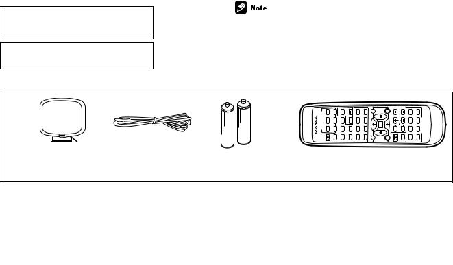
Furnished Parts |
|
|
AM loop antenna ............................................................................ |
|
1 |
FM wire antenna ............................................................................ |
|
1 |
Dry cell batteries (AA size IEC R6P) .............................................. |
2 |
|
Remote control ............................................................................... |
|
1 |
Operating instructions .................................................................... |
|
1 |
Specifications and the design are subject to possible modifications without notice, due to improvements.
A
B
C
D
 Accessories
E
INPUTSELECTOR DVD/LDRECEIVERTV/SAT CD |
VCR/ DVR |
MASTER |
FLINPUT DIMMERATT MUTE |
TUNING STATION |
CLASSBAND MPX DISPLAY |
MENU TOPMENU |
RECEI- |
DVD VER |
DVD |
EFFECT |
TITLESUB 1 3 ¡ |
87 4 ¢ |
DVDCONTROL |
AVRECEIVER Î |
MIDNIGHT/ LOUDNESS |
ADVANCED SURROUNDSTANDARDSTEREOVOLUME |
TUNER EDIT ENTER |
AUDIO |
|||||||||||
|
R/ - CD TAPE/MD |
|
|
|
|
|
SETUP |
|
SELECTCH |
LEVEL |
|
|
|
|
|
TUNER |
|
|
|
|
|
|
TEST TONE |
|
|
|
|
AM loop antenna |
FM wire antenna |
AA size IEC R6P |
Remote control unit |
(ATB7009) |
(ADH7005) |
Dry cell batteries (x2) |
(XXD3039) |
F
|
|
|
|
|
|
|
|
|
VSX-D511-K |
7 |
5 |
||
5 |
6 |
|
|
|
8 |
|

1 |
2 |
3 |
4 |
2. EXPLODED VIEWS AND PARTS LIST
NOTES:  Parts marked by "NSP" are generally unavailable because they are not in our Master Spare Parts List.
A
 The
The  mark found on some component parts indicates the importance of the safety factor of the part. Therefore, when replacing, be sure to use parts of identical designation.
 Screws adjacent to
  mark on product are used for disassembly.
 For the applying amount of lubricants or glue, follow the instructions in this manual. (In the case of no amount instructions, apply as you think it appropriate.)
2.1 PACKING
B
1
3 
2
4
5
C
/MYXJIEW Type |
6 |
14 |
7
8
9
11
10
12
D
13
E
F
6 |
|
VSX-D511-K |
|
|
1 |
2 |
|
3 |
4 |

5 6 7 8
PACKING parts List
Mark No. |
Description |
Part No. |
Mark No. |
Description |
Part No. |
|
|
1 |
FM wire antenna |
ADH7005 |
8 |
Battery Cover |
AZA7378 |
NSP |
2 |
Warranty Card |
ARY7022 |
NSP 9 |
Polyethylene Bag |
Z21-038 |
|
3 |
AM loop antenna |
ATB7009 |
10 |
Packing Sheet |
AHG7069 |
NSP |
4 |
Dry cell batteries (AA/R6P) |
VEM-013 |
|
|
|
|
5 |
Operating instructions |
XRE3057 |
11 |
Left Pad R5 |
XHA3032 |
|
|
(English/German) |
|
12 |
Right Pad R5 |
XHA3033 |
|
|
|
|
13 |
Packing Case |
See Contrast table(2) |
|
6 |
Operating instructions |
See Contrast table(2) |
14 |
Operating instructions |
See Contrast table(2) |
|
7 |
Remote Control Unit |
XXD3039 |
|
|
|
(2) CONTRAST TABLE
VSX-D511-K/MVXJI, /MYXJIEW, /MYXJIGR and VSX-D511-S/MYXJIEW are constructed the same except for the following :
Mark |
NO |
Symbol and Description |
VSX-D511-K/ |
VSX-D511-S/ |
VSX-D511-K/ |
VSX-D511-K/ |
|
MVXJI |
MYXJIEW |
MYXJIEW |
MYXJIGR |
||||
|
|
|
|||||
|
|
|
|
|
|
|
|
|
6 |
Operating Instructions (French,Italian) |
Not used |
XRC3056 |
XRC3056 |
Not used |
|
|
13 |
Packing Case |
XHD3204 |
XHD3205 |
XHD3204 |
XHD3204 |
|
|
14 |
Operating Instructions (Spanish,Dutch) |
Not used |
XRC3070 |
XRC3070 |
Not used |
|
|
|
|
|
|
|
|
A
B
C
D
E
F
|
|
|
|
|
|
|
|
|
VSX-D511-K |
7 |
7 |
||
5 |
6 |
|
|
|
8 |
|

1 |
2 |
3 |
4 |
2.2 EXTERIOR SECTION
A |
|
|
|
|
|
|
|
|
|
|
|
|
|
|
|
|
|
|
|
|
|
|
|
|
|
35 |
|
42 |
|
|
|
|
|
|
|
|
|
|
|
42 |
|
|
|
|
|
|
|
|
|
|
|
|
|
|
|
|
|
|
|
|
|
|
|
|
|
|
|
|
|
|
|
53 |
|
|
|
|
|
|
|
|
|
|
|
|
|
41 |
|
53 |
|
|
|
|
|
|
|
|
|
|
|
|
|
|
|
|
|
|
|
56 |
|
|
|
|
|
57 |
|
|
|
|
|
|
53 |
|
|
|
|
||
|
|
|
|
|
|
|
|
|
|
|
|
|
|||
B |
|
|
|
|
|
|
|
|
|
|
|
|
|
|
|
|
|
|
|
21 |
22 |
|
|
|
|
|
23 |
|
|
|
|
|
|
|
|
|
|
|
|
24 |
|
|
|
|
|||
|
|
|
|
|
|
I |
|
|
|
|
|
|
|
|
|
|
|
|
|
|
|
|
|
|
|
|
|
|
53 |
|
|
|
|
|
|
53 |
54 |
22 |
|
|
|
40 |
|
|
53 |
53 |
|
|
|
|
|
|
53 |
|
|
|
|
|
|
||||
|
|
|
|
|
|
|
|
|
|
|
|
|
|
||
|
|
|
|
|
|
|
57 |
|
|
|
|
|
53 |
53 |
|
|
|
B 2 |
|
|
|
|
C |
I |
|
|
|
|
|||
|
50 |
|
J |
|
|
|
|
|
|
|
|
|
|||
|
|
|
|
|
|
9 J |
|
|
|
|
|
|
53 |
||
|
|
|
|
53 |
|
|
30 |
|
|
|
|
|
|
53 |
|
|
|
|
|
|
|
|
|
|
|
|
|
|
|||
C |
|
|
|
H |
|
50 |
|
|
|
|
|
|
|
|
53 |
|
53 |
54 |
|
|
G |
|
|
|
N |
|
|
|
|
|
|
|
|
|
|
|
|
|
|
|
53 |
|
|
53 |
|||
|
H 4 |
|
|
M |
|
|
|
46 |
N |
31 |
|
|
|
||
|
K |
|
|
|
53 |
10 |
|
|
|
|
|
||||
|
|
|
|
|
|
|
|
|
|
||||||
|
|
L |
|
|
|
|
|
G 7 |
|
27 |
E |
N |
8 M |
|
|
|
|
|
|
|
|
|
|
49 |
|
34 |
|
|
|||
|
|
|
|
|
|
|
|
|
|
|
39(1/2) |
|
|||
|
|
|
|
|
|
|
|
|
|
|
|
|
|
||
|
|
|
D |
|
|
53 |
|
48 |
|
|
|
|
|
53 |
|
|
|
|
|
|
|
|
|
L 15 |
|
|
|
|
|
||
|
|
|
|
|
|
|
|
|
|
|
|
|
|
|
|
|
17 D |
I |
16 |
J |
53 |
|
|
53 |
|
|
|
|
|
||
|
|
|
47 |
53 |
|
|
43 |
|
|
||||||
|
|
|
|
|
|
H |
|
53 |
|
|
|
28 |
|||
|
|
|
|
|
|
|
|
|
|
|
|
|
|
||
|
M |
|
|
|
|
|
|
|
|
|
A 1 |
|
|
F |
|
D |
L |
|
|
|
|
|
|
|
|
|
|
|
|||
|
|
|
5 C |
|
|
|
|
25 |
|
|
|
|
|||
K |
|
|
|
|
|
|
|
|
|
|
|
||||
|
|
|
|
|
|
|
|
|
|
|
|
||||
|
|
|
|
|
|
55 |
51 |
44 |
|
|
A |
53 |
|
|
|
|
|
|
|
|
|
|
|
53 |
29 |
C |
|
|
|
|
|
|
|
|
|
|
|
|
|
|
D |
53 |
|
|
|
|
|
|
|
|
|
|
|
55 |
|
|
|
|
|
39(2/2) |
|
||
|
|
|
|
|
|
|
|
|
|
|
|
|
|
||
|
20 |
|
|
|
|
|
|
|
|
|
|
|
|
|
18 X |
|
|
|
|
|
|
|
|
|
|
|
|
|
|
|
E |
|
|
|
|
|
|
|
|
|
|
|
|
|
|
F |
|
|
|
|
|
|
|
|
|
|
|
|
|
3 E |
13 K |
|
|
|
|
|
|
|
|
|
|
|
|
|
|
|
|
||
|
|
|
|
G |
|
|
|
|
|
|
|
26 |
|
|
|
|
|
|
|
|
|
|
|
|
|
|
|
|
|
|
|
|
53 |
|
|
|
|
|
|
|
|
|
|
B |
|
53 |
|
|
|
|
|
|
|
|
|
|
|
|
|
|
|||
E |
|
|
|
|
|
Accessory of |
|
|
|
|
|
6 |
F |
|
53 |
|
|
|
|
|
|
|
|
|
|
|
|
|
|
||
|
|
|
|
|
|
Front Panel |
|
|
|
|
|
|
|
|
|
|
|
|
|
|
|
|
|
|
37 |
38 |
|
|
|
|
|
|
|
|
|
|
|
|
53 |
|
|
|
|
|
45 |
||
|
|
|
|
|
|
|
|
|
53 |
|
|
|
|
||
|
|
|
|
|
|
|
A |
|
|
|
|
|
|
|
|
|
|
|
|
|
|
|
|
|
|
NON-CONTACT |
|
|
|||
|
|
|
|
|
|
|
|
|
|
|
|
|
|||
|
|
|
|
|
|
|
|
|
|
|
SIDE |
CONTACT |
|
|
|
|
|
|
|
|
|
|
|
B |
|
|
|
|
|
||
|
53 |
|
|
|
|
|
|
|
|
|
SIDE |
|
|
|
|
|
|
|
|
|
|
|
38 |
|
|
|
|
|
|
||
|
|
|
|
|
|
|
53 |
|
|
|
|
|
|
|
|
|
|
|
|
|
|
|
53 |
|
|
|
|
|
|
|
|
|
Refer to |
|
|
|
|
|
|
|
|
|
|
|
|
|
|
|
"2.3 FRONT PANEL SECTION". |
|
|
|
|
|
|
|
|
|
|||||
F |
|
|
|
|
|
|
|
|
|
|
|
|
|
|
|
|
8 |
|
|
|
|
|
|
VSX-D511-K |
|
|
|
|
|
|
|
|
1 |
|
|
|
|
|
2 |
|
|
3 |
|
|
|
|
4 |

|
5 |
6 |
EXTERIOR SECTION parts List |
|
|
Mark No. |
Description |
Part No. |
1 |
D.D & INPUT ASSY |
XWX3044 |
2 |
AMP ASSY |
XWZ3533 |
3 |
REGULATOR ASSY |
XWZ3544 |
4 |
AMP INPUT ASSY |
XWZ3547 |
5 |
TRANS2 ASSY |
XWZ3555 |
6 |
HASHIGETA ASSY |
XWZ3566 |
7 |
BOARD TO BOARD ASSY |
XWZ3527 |
8 |
6CH IN ASSY |
XWZ3507 |
9 |
DIGITAL IN ASSY |
XWZ3518 |
10 |
S. VIDEO ASSY |
XWZ3521 |
11• • • • •
12• • • • •
|
13 |
KAWA ASSY |
XWZ3529 |
|
14 |
• • • • • |
|
|
15 |
VIDEO ASSY |
XWZ3490 |
NSP 16 |
TRANS1 ASSY |
XWZ3552 |
|
NSP 17 |
TRANS3 ASSY |
XWZ3560 |
|
|
18 |
FM/AM TUNER MODULE |
AXQ7232 |
|
19 |
• • • • • |
|
> |
20 |
Power Transformer (T1) |
ATS7259 |
|
21 |
• • • • • |
|
> |
22 |
Fuse (FU1:T2.5A) |
REK1026 |
> |
23 |
Power Cord |
See Contrasttable(2) |
|
24 |
Cord Stopper |
CM-22B |
|
25 |
28P F•F•C/30V (J31) |
XDD3097 |
|
|
DD CN102 - FRONT CN402 |
|
|
26 |
17P F•F•C/30V (J32) |
XDD3098 |
|
|
KAWA CN5001 - FRONT CN401 |
|
|
27 |
7P F•F•C/30V (J33) |
XDD3099 |
|
|
KAWA CN5004 - VIDEO CN503 |
|
|
28 |
13P F•F•C/30V (J34) |
XDD3100 |
|
|
KAWA CN5005 - FM/AM TUNER CN201 |
|
|
29 |
19P F•F•C/30V (J35) |
XDD3101 |
|
7 |
8 |
Mark No. |
Description |
Part No. |
DD CN106 - AMP INPUT CN254
30 23P F•F•C/30V (J36) XDD3102 AMP CN53 - REGULATOR CN801
31 7P F•F•C/30V (J37) |
XDD3103 |
DD CN9101 - DIGITAL IN CN1901
32• • • • •
33• • • • •
34 |
9P F•F•C/30V (J48) |
XDD3106 |
|
DD CN104 - 6CH IN CN307 |
|
35 |
Top Cover |
See Contrast table(2) |
36 |
• • • • • |
|
NSP 37 |
Under Base 409 |
ANA7094 |
38 |
Insulator |
PNW2766 |
39 |
FFC Cover R5 |
XMR3047 |
40 |
Rear Panel |
XNC3143 |
41 |
Bonnet D510 |
See Contrast table(2) |
42 |
Push Rivet |
See Contrast table(2) |
43 |
Tuner Shield R5 |
XNG3072 |
44 |
PCB Angle R5 |
XNG3073 |
45 |
Reg Support R5 |
XNG3074 |
NSP 46 |
Heat Sink Assy 0.8 |
ANH7118 |
47 |
Heat Sink Angle F |
ANG7251 |
48 |
Heat Sink Angle R |
ANG7252 |
NSP 49 |
Heat Sink 0.8 |
ANH7110 |
50 |
Screw 3x23 |
ABA7043 |
51 |
PCB Mold |
AMR2533 |
52 |
Screw |
See Contrast table(2) |
53 |
Screw |
BBZ30P080FMC |
54 |
Screw |
BBZ30P200FMC |
55 |
Screw |
FBT40P080FZK |
56 |
Tuner Sheet |
XEC3031 |
57 |
Screw |
See Contrast table(2) |
(2) CONTRAST TABLE
VSX-D511-K/MVXJI, /MYXJIEW, /MYXJIGR and VSX-D511-S/MYXJIEW are constructed the same except for the following :
Mark |
NO |
Symbol and Description |
VSX-D511-K/ |
VSX-D511-S/ |
VSX-D511-K/ |
VSX-D511-K/ |
|
MVXJI |
MYXJIEW |
MYXJIEW |
MYXJIGR |
||||
|
|
|
|||||
|
|
|
|
|
|
|
|
> |
23 |
AC Power Cord |
VDG1076 |
VDG1077 |
VDG1077 |
VDG1077 |
|
|
35 |
Top Cover |
XME3004 |
XME3006 |
XME3004 |
XME3004 |
|
|
41 |
Bonnet |
XZN3111 |
XZN3122 |
XZN3111 |
XZN3111 |
|
|
42 |
Push Rivet |
AEC7025 |
XEC3026 |
AEC7025 |
AEC7025 |
|
|
57 |
Screw |
FBT40P080FZK |
FBT40P080FNI |
FBT40P080FZK |
FBT40P080FZK |
|
|
|
|
|
|
|
|
A
B
C
D
E
F
|
|
|
|
|
|
|
|
|
VSX-D511-K |
7 |
9 |
||
5 |
6 |
|
|
|
8 |
|
1 |
2 |
3 |
4 |
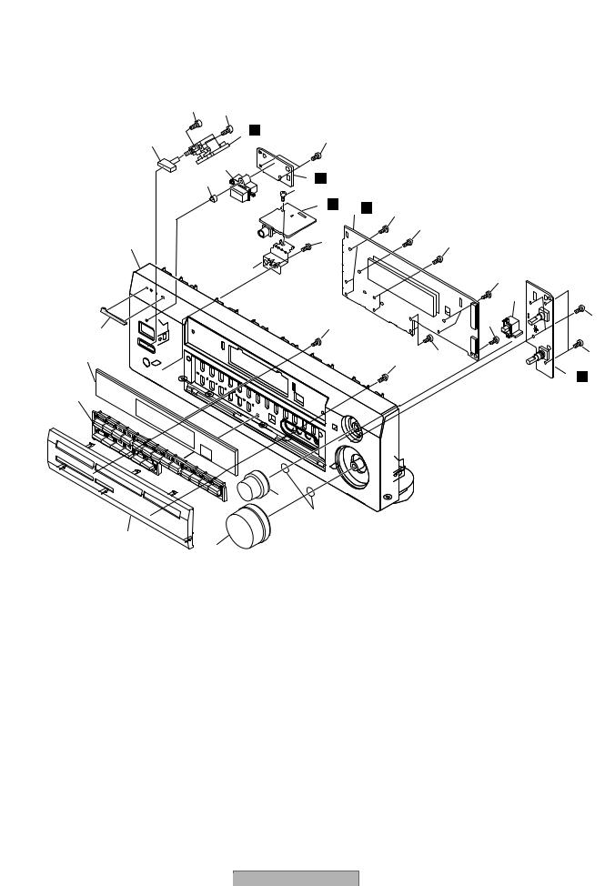
2.3 FRONT PANEL SECTION
A |
|
|
|
|
|
|
|
|
|
16 |
16 |
|
|
|
|
|
|
|
|
|
|
|
|
|
|
|
|
|
5 |
Y |
|
|
|
|
|
|
19 |
|
16 |
|
|
|
|
|
|
|
|
|
|
|
|
|
|
|
|
13 |
|
|
|
|
|
|
B |
|
10 |
2 Q |
|
|
|
|
|
|
|
17 |
|
|
|
|
|
|
|
|
|
|
|
|
|
|
|
|
|
|
3 |
U |
1 O |
16 |
|
|
|
|
|
|
|
|
|
||
|
|
|
|
|
|
|
16 |
|
|
6 |
|
16 |
|
|
16 |
|
|
|
|
8 |
|
|
|
|
16 |
|
|
|
|
|
|
|
|
|
|
|
|
|
|
|
|
|
|
15 |
|
9 |
|
|
16 |
|
|
16 |
16 |
|
|
|
|
|
|
|
|
|
C |
|
|
|
|
|
|
16 |
|
|
18 |
|
|
|
|
16 |
16 |
|
|
|
|
|
|
|
|
||
|
|
|
|
|
|
|
|
4 P |
|
7 |
|
|
|
|
|
|
|
D |
|
|
11 |
|
|
|
|
|
|
|
|
|
|
|
|
|
|
|
|
|
20 |
|
|
|
|
|
|
14 |
|
|
|
|
|
|
|
|
|
12 |
|
|
|
|
|
|
E |
|
|
|
|
|
|
|
|
F |
|
|
|
|
|
|
|
|
10 |
|
|
VSX-D511-K |
|
|
|
|
|
1 |
|
2 |
|
|
3 |
|
|
4 |
5 6 7 8
FRONT PANEL SECTION parts List
Mark No. |
Description |
Part No. |
Mark No. |
Description |
Part No. |
1 |
FRONT ASSY |
XWZ3493 |
11 |
Select Knob |
See Contrast table(2) |
2 |
POWER SW ASSY |
XWZ3510 |
12 |
Volume Knob |
See Contrast table(2) |
3 |
H.P. ASSY |
XWZ3513 |
13 |
Power Button |
See Contrast table(2) |
4 |
R. ENCODER ASSY |
XWZ3511 |
14 |
Sub Panel |
See Contrast table(2) |
5 |
MECH SW ASSY |
XWZ3514 |
15 |
Jog Button |
See Contrast table(2) |
6 |
Front Panel |
See Contrast table(2) |
16 |
Screw |
PPZ30P080FMC |
7 |
Sub Button |
See Contrast table(2) |
17 |
Screw |
BBZ30P080FMC |
8 |
Earth Plate R5 HP |
XNG3066 |
18 |
D Panel R5 W |
XAK3320 |
9 |
Pioneer Badge |
See Contrast table(2) |
19 |
Power Button M |
See Contrast table(2) |
10 |
Led Lens 1.6 |
XAK3308 |
20 |
C Ring DIA8.1 |
XBH3016 |
(2) CONTRAST TABLE
VSX-D511-K/MVXJI, /MYXJIEW, /MYXJIGR and VSX-D511-S/MYXJIEW are constructed the same except for the following :
Mark |
NO |
Symbol and Description |
VSX-D511-K/ |
VSX-D511-S/ |
VSX-D511-K/ |
VSX-D511-K/ |
|
MVXJI |
MYXJIEW |
MYXJIEW |
MYXJIGR |
||||
|
|
|
|||||
|
|
|
|
|
|
|
|
|
6 |
Front Panel |
XMB3065 |
XMB3076 |
XMB3065 |
XMB3065 |
|
|
7 |
Sub Button |
XAD3125 |
XAD3133 |
XAD3125 |
XAD3125 |
|
|
9 |
Pioneer Badge |
XAM3006 |
VAM1129 |
XAM3006 |
XAM3006 |
|
|
11 |
Select Knob |
XAB3023 |
XAB3024 |
XAB3023 |
XAB3023 |
|
|
12 |
Volume Knob |
XAB3025 |
XAB3026 |
XAB3025 |
XAB3025 |
|
|
13 |
Power Button |
XAD3123 |
XAD3129 |
XAD3123 |
XAD3123 |
|
|
14 |
Sub Panel |
XAK3273 |
XAK3299 |
XAK3273 |
XAK3273 |
|
|
15 |
Jog Button |
XAD3124 |
XAD3131 |
XAD3124 |
XAD3124 |
|
|
19 |
Power Button M |
XAD3127 |
XAD3137 |
XAD3127 |
XAD3127 |
|
|
|
|
|
|
|
|
A
B
C
D
E
F
|
|
|
|
|
|
|
|
|
VSX-D511-K |
7 |
11 |
||
5 |
6 |
|
|
|
8 |
|

1 |
2 |
3 |
4 |
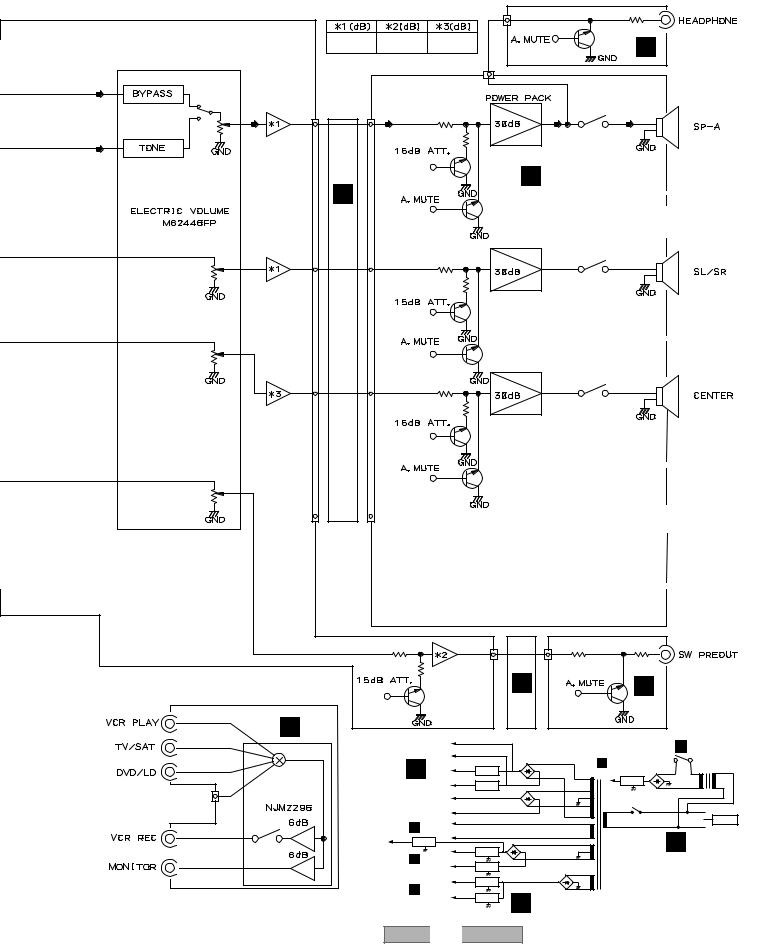
3. BLOCK DIAGRAM AND SCHEMATIC DIAGRAM
3.1 BLOCK DIAGRAM
A
X |
CN201 |
K CN101 |
A D.D & INPUT ASSY |
|
|
7 |
10 |
||
|
AXQ7232 |
|
|
IC101 |
|
|
|
|
TC9273F-007 |
|
|
|
7 |
(FUNCTION SEL) |
|
|
5 |
|
|
|
IC104 |
|
|
|
|
|
|
|
|
|
|
|
|
|
|
|
12 |
|
|
|
|
|
|
|
|
|
|
|
|
|
4 |
|
|
3 |
1 |
|
|
|
|
|
|
|
3 |
|
|
|
|
|
|
|
|
|
|
|
|
|
|
|
|
|
||
|
|
3 |
|
|
|
|
|
|
|
|
|
|
|
|
|
|
|
|
2 |
|
|
|
|
|
IC9201 |
|
|
|
|
|
4 |
5 |
|
|
|
|
|
|
|
|
3 |
1 NJM2100M |
|
|
|
|
|
|
|
|
B |
|
8 |
|
|
|
|
|
|
|
|
|
|
|
|
IC102 |
|
1 |
|
|
|
|
|
|
|
|
|
|
|
|
|
|||
|
|
|
|
IC9101 AK4586 |
NJM4558MD |
NJM4558MD |
NJU7312AM |
|
||||||||
|
|
|
|
|
|
|
||||||||||
|
|
|
|
|
|
32 |
(CODEC) |
|
|
|
||||||
|
CN107 |
|
|
|
30 |
(LPF) |
|
|
(6dB AMP) |
|
|
|||||
|
|
|
|
|
|
|
|
(EXP/DSP) |
|
|||||||
|
|
9 |
|
|
|
|
|
28 |
IC9701 |
|
|
IC9704 |
|
|||
|
|
|
|
|
|
|
2 |
1 |
(FL/FR) |
2 |
1 |
|
|
|||
|
|
|
|
|
(ADC) |
(DAC) |
26 |
|
|
|||||||
|
|
|
|
|
|
27 |
|
|
|
|
|
|
|
|
||
|
|
|
|
10 |
11 |
|
11-13 |
|
|
|
|
|
|
6 |
|
|
|
|
|
|
|
|
|
|
(SL/SR) |
|
|
|
|||||
|
|
|
|
|
|
|
39-40 |
IC9702 |
IC9705 |
|
|
|||||
|
|
|
|
|
|
|
IC9601 |
|
9 |
|||||||
|
|
|
|
|
|
|
|
|
2 |
1 |
2 |
1 |
8 |
|||
|
|
|
|
|
|
|
IC9501 |
|
|
NJU7313 |
|
|
|
|
||
|
|
|
|
|
|
|
|
|
AM |
|
|
|
|
|||
|
|
|
|
|
|
(DIR) |
CRYSTAL |
|
|
|
|
|
|
|||
|
|
|
|
|
|
|
|
(SP |
|
|
7 |
|
||||
|
|
|
|
|
|
|
DSP |
|
|
|
|
|
|
|||
|
|
2 |
|
|
|
10 |
|
IC9703 |
|
|
|
|
||||
|
|
|
|
|
22 (for DECODE) |
|
config) |
|
|
|
|
|||||
|
|
|
IC1901 |
|
|
|
3 |
1 |
|
(C) |
|
|
|
|
||
|
|
1 |
5 |
6 |
2 |
|
|
|
|
|
|
|
|
|
|
|
|
|
43 |
|
|
|
|
|
|
|
|
|
|
||||
|
|
|
|
|
|
|
|
|
|
|
|
|
|
|
|
|
|
|
15 |
CN1901 |
CN9101 |
|
|
IC9703 |
|
|
|
|
21 |
|
|||
|
|
|
|
|
|
|
|
|
|
|
|
|
|
|
||
C |
|
|
|
|
IC9508 |
IC9502 |
5 |
7 |
|
(SW) |
|
|
|
19 |
||
|
|
|
|
BS62LV |
|
|
|
|
|
|
|
|||||
|
|
|
|
TC74 |
|
|
|
|
|
|
|
20 |
|
|||
|
|
|
|
|
1024TC-70 |
VHC574F |
|
|
|
|
|
|
|
|||
|
|
|
|
|
(RAM for |
|
|
|
|
|
|
|
|
|||
|
|
|
|
|
IC9503 |
|
|
|
|
|
|
|
|
|||
|
|
13 |
|
|
|
AAC) |
|
|
|
|
|
|
|
|
||
|
|
|
|
|
TC74 |
|
|
|
|
|
|
|
|
|
||
|
|
|
|
IC9504 |
|
|
|
|
|
|
|
|
|
|||
|
|
1 |
|
|
VHC574F |
|
|
|
|
|
|
|
|
|||
|
CN1902 5 |
|
J |
PDN030A |
(8 16bit) |
|
|
|
|
|
|
|
|
|||
|
|
|
|
(ROM for |
|
|
|
|
|
|
|
|
|
|
||
|
|
|
|
DECODE) |
|
|
|
|
|
|
|
|
|
|
||
|
|
|
|
|
|
|
|
|
|
|
|
|
|
|
||
|
|
DIGITAL IN ASSY |
|
|
|
|
|
|
|
|
|
|
|
|
||
|
3 |
IC303 |
CN307 |
|
CN104 |
|
|
|
|
|
|
|
|
|
|
|
|
1 |
|
|
|
|
|
|
|
|
|
|
|
||||
|
|
3 |
|
7 |
|
|
|
|
|
|
|
|
|
|
|
|
|
M |
|
|
|
|
|
|
|
|
|
|
|
|
|
11 |
|
|
IC302 |
|
|
|
|
|
|
|
|
|
|
|
|
|
12 |
|
|
5 |
9 |
|
1 |
|
|
|
|
|
|
|
|
|
10 |
|
|
|
|
7 |
|
|
|
|
|
|
|
|
|
|
|
|
||
D |
IC302 |
|
|
3 |
5 |
5 |
|
|
1 |
6CH IN ASSY
|
|
IC352 |
(Y SEL) |
|
|
|
9 |
|
|
|
|
5 |
|
|
E |
|
7 |
|
|
|
|
|
|
|
|
3 |
3 |
|
|
|
|
1 |
11 |
1 |
|
|
IC351 |
||
|
|
9 |
(C SEL) |
|
|
|
|
|
|
|
|
5 |
|
|
S. VIDEO |
N |
7 |
|
|
ASSY |
|
|
|
|
|
|
|
|
|
|
|
3 |
|
|
|
|
11 |
1 |
|
F
12 |
|
VSX-D511-K |
|
|
1 |
2 |
|
3 |
4 |
5 |
|
|
|
|
6 |
|
|
|
|
7 |
|
|
8 |
|
|
|
|
|
|
|
|
|
|
|
|
|
A |
|
|
|
|
|
|
|
|
|
|
CN1551 |
|
|
|
|
|
|
|
|
|
|
|
|
|
6 |
|
|
|
|
|
|
|
|
14.1/24.1 |
14.7/27.3 |
13.8 |
|
|
Q1552 |
U |
|
|
|
|
|
|
|
|
|
|
|
|
|
|
||
17 |
|
|
|
|
|
|
CN702 |
6 |
|
|
|
|
|
|
|
IC105 |
|
|
|
|
|
|
|
|
|
|
|
|
|
uPC2570 |
|
|
|
|
|
|
|
|
|
|
|
|
|
(PRE AMP) |
|
|
CN601 |
|
|
|
IC601 |
RY751 |
|
|
|
|
|
|
|
4 |
|
|
22 |
|
|
|
|
|
|
|
31 |
5 |
7 |
|
9 |
|
|
15 |
|
|
|
||
15 |
|
|
CN106 |
|
|
|
|
|
|
|
|
|
|
|
|
|
|
|
|
|
|
|
|
|
|
|
|
|
|
|
|
|
|
Q603 |
|
|
B |
|
|
B |
|
|
|
|
|
|
H |
|
|
|
|
|
|||
IC103 |
|
|
|
|
|
|
|
|
AMP & PRIMARY ASSY |
|
|
||
|
|
|
|
|
|
|
Q601 |
|
|
|
|
|
|
9 |
|
|
IC106 |
|
|
|
|
|
|
IC602 |
RY753 |
|
|
|
|
|
|
|
|
|
|
|
|
|
|||
|
34 |
5 |
7 |
8 |
|
5 |
|
24 |
|
26 |
|
|
|
|
|
|
|
|
ASSY |
|
|
|
|
|
|
|
|
|
|
|
|
|
INPUT |
Q653 |
|
|
|
|
|
|
|
11 |
|
|
|
|
|
|
|
|
|
|
|
C |
|
|
33 |
|
|
|
|
|
|
|
|
|
|
||
|
|
|
|
AMP |
|
|
|
|
|
|
|
||
|
|
|
IC107 |
|
|
Q651 |
|
|
IC601 |
RY752 |
|
|
|
|
|
3 |
1 |
|
|
|
|
|
|
|
|
||
|
|
1 |
|
11 |
|
|
|
26 |
|
|
|
||
|
|
|
|
|
|
|
|
|
|
|
|||
|
|
|
|
|
|
|
|
24 |
|
|
|
|
|
|
|
|
|
|
|
Q632 |
|
|
|
|
|
|
|
6 |
|
|
|
|
|
|
|
|
|
|
|
|
|
|
36 |
|
|
|
|
|
Q631 |
|
|
|
|
|
|
|
|
|
|
|
|
|
|
|
|
|
|
|
|
|
|
|
|
|
|
|
|
|
|
|
|
|
D |
|
|
|
|
|
|
5 |
7 |
14 |
|
1 |
|
|
|
|
|
|
|
|
|
|
CN101 |
|
CN302 |
|
|
|
|
|
|
|
|
|
|
IC107 |
|
|
E |
L |
|
|
|
|
VIDEO ASSY |
|
|
|
|
|
|
E |
|||||
|
|
|
|
|
|
|
Q303 |
|
|||||
|
|
|
|
|
|
Q112 |
|
|
|
|
|
|
|
|
|
|
|
|
|
|
|
|
|
|
|
|
|
|
9 |
|
L |
|
|
|
|
|
|
|
|
|
|
|
|
|
|
|
|
+BVH |
|
|
|
|
|
|
|
|
5 |
|
|
|
|
|
|
|
|
|
Y |
|
|
|
|
|
|
|
|
-BVH |
|
|
|
|
|
||
|
|
|
|
|
|
|
|
|
|
|
MECHA SW |
||
|
7 |
|
|
|
|
B |
NECK+B |
Q701 |
|
D701 |
A CN101 |
|
ASSY |
|
|
|
|
|
|
U+5V |
|
|
|||||
|
3 |
|
IC301 |
|
|
POWER AMP |
NECK-B |
Q702 |
|
|
IC51 |
|
|
6 |
|
|
|
|
|
|
|
|
|
||||
(CONPONENT SEL) |
|
IC601, IC602 |
+BVL |
|
|
D702 |
D51-D54 |
T51 |
|||||
|
|
|
|
|
|
|
|||||||
|
|
|
|
|
|
|
|
|
|
RY51 |
|
|
|
|
|
|
|
|
|
|
-BVL |
|
|
|
|
|
|
|
|
|
|
|
|
|
|
|
|
|
|
|
|
|
|
|
|
|
|
|
FL AC |
|
|
|
|
|
AC IN |
|
11 |
|
|
|
|
O CN402 |
|
|
|
|
|
|
|
|
|
|
|
|
T+12V |
FL AC |
|
|
|
T1 |
B |
|
|
|
|
|
|
|
|
IC805 |
+12V |
|
|
|
|
||
|
|
|
|
|
|
|
|
|
POWER |
|
|||
|
|
|
|
|
|
|
IC801 |
D801–D804 |
|
||||
|
|
|
|
|
|
A CN101 -12V |
TRANSFORMER |
|
|
||||
|
1 |
|
|
|
|
|
|
|
|
F |
|||
|
|
|
|
|
IC802 |
|
|
|
|||||
|
|
|
|
|
|
|
D721–D724 |
|
|||||
|
|
|
|
|
|
|
D+5V |
|
|
|
|
||
|
|
|
|
|
|
|
IC803 |
|
|
|
|
||
|
|
|
|
|
|
A CN101 A+5V |
|
|
|
|
|||
|
|
|
|
|
|
IC804 |
E |
|
|
|
|||
|
|
|
|
|
|
|
|
|
|
|
|||
|
|
|
|
|
|
VSX-D511-K |
|
7 |
|
|
13 |
||
5 |
|
|
|
|
6 |
|
|
|
|
|
|
8 |
|

1 |
2 |
3 |
4 |
3.2 OVERALL WIRING CONNECTION DIAGRAM
A
R.ENCODER ASSY
(XWZ3511) P  FRONT ASSY O (XWZ3493)
B
C
D
E
F
H
AMP INPUT ASSY (XWZ3547)
F |
D.D & |
|
|
|
INPUT |
|
|
|
|
HASHIGETA |
ASSY |
|
|
|
(XWX3044) |
|
|
|
|
ASSY |
|
|
|
|
A |
|
|
|
|
(XWZ3566) |
|
|
|
|
KAWA |
K |
|
|
|
ASSY |
|
|
|
|
(XWZ3529) |
A 1/4, |
S. VIDEO |
N |
BOARD TO |
|
ASSY |
|||
|
A 2/4, |
(XWZ3521) |
|
BOARD |
|
|
ASSY |
||
|
|
|
||
|
A 3/4, |
|
|
G (XWZ3527) |
|
|
|
|
|
|
A 4/4 |
REGULATOR |
|
|
|
|
|
|
|
|
|
ASSY |
VIDEO |
|
|
|
(XWZ3544) |
ASSY |
|
X |
|
E (XWZ3490) |
||
|
|
L |
|
|
FM/AM TUNER |
|
|
M |
|
MODULE |
|
|
|
|
(AXQ7232) |
|
|
|
|
6CH IN ASSY (XWZ3507)
14 |
|
VSX-D511-K |
|
|
1 |
2 |
|
3 |
4 |

5 |
6 |
7 |
8 |
A
Note : When ordering service parts, be sure to refer to "EXPLODED VIEWS and PARTS LIST" or "PCB PARTS LIST".
|
Q |
POWER SW ASSY |
|
(XWZ3510) |
|
|
Y |
|
U |
MECHA SW ASSY |
|
(XWZ3514) |
||
H.P. ASSY |
|
|
(XWZ3513) |
|
B |
D
TRANS3 ASSY (XWZ3560)
C
J6 J7
J3(J8) |
(ATS7259) |
|
TRANS2 |
TRANS1 |
|
|
ASSY |
ASSY |
|
B |
(XWZ3555) |
(XWZ3552) |
|
|
I |
|
|
B 1/2, |
C |
D |
|
B 2/2 |
|
J2 |
J1 |
|
|
||
AMP& |
J4 |
|
|
||
PRIMARY |
J5 |
|
ASSY |
||
|
||
(XWZ3533) |
|
FU1 : REK1026(T2.5A/250V)
E
J
DIGITAL IN
ASSY F (XWZ3518)
VDG1076 : /MVXJI
VDG1077 : /MYXJI
|
|
|
|
|
|
|
|
|
VSX-D511-K |
7 |
15 |
||
5 |
6 |
|
|
|
8 |
|
1 |
2 |
3 |
4 |
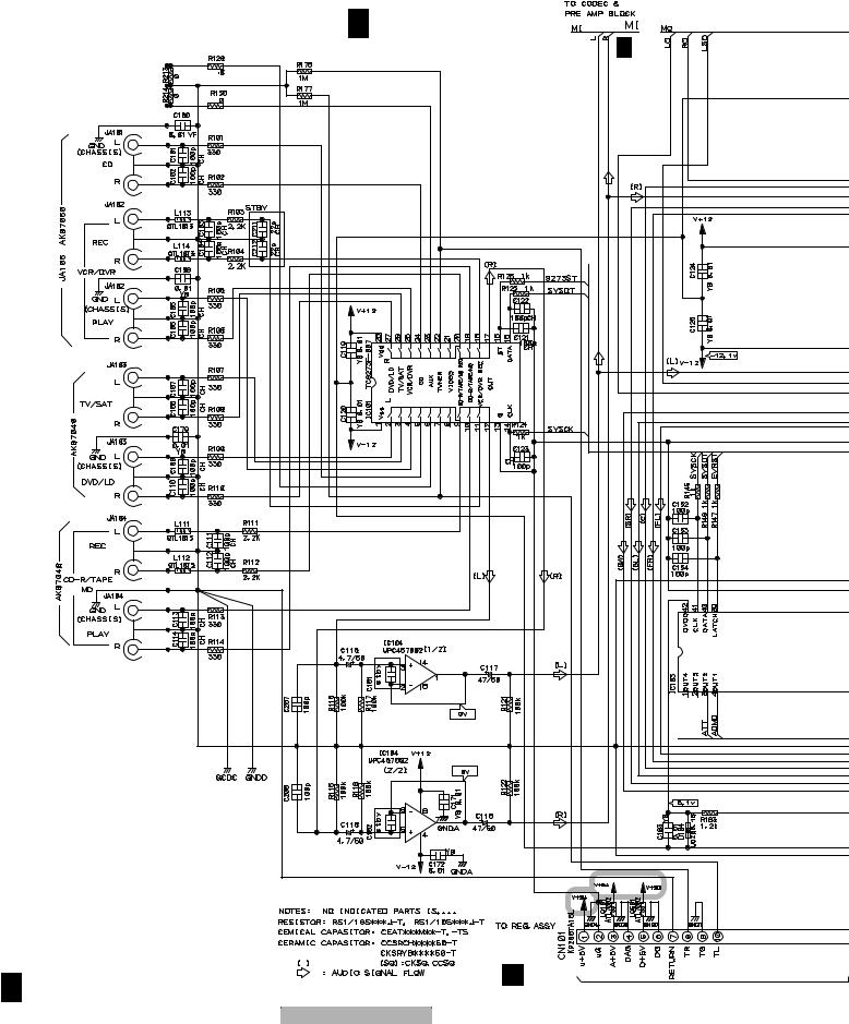
3.3 D.D & INPUT(1/4) ASSY |
|
|
|
A |
|
|
|
|
|
A 1/4 D.D & INPUT ASSY |
|
|
|
(XWX3044) |
A 2/4 |
B |
|
|
|
C |
|
|
|
D |
|
|
|
E |
|
|
|
F |
|
|
|
1/4 |
|
E CN802 |
|
A |
|
|
|
16 |
|
VSX-D511-K |
|
1 |
2 |
3 |
4 |
5 |
6 |
7 |
8 |
A
A 4/4 |
M CN307 |
|
|
: The power supply is shown with the marked box. |
|||
|
A 4/4 |
|
|
|
|
A 2/4,4/4 |
CN402 |
|
A 4/4 |
A 2/4,3/4,4/4 |
|
|
|
O |
|
|
|
|
|
B
C
 A 2/4
A 2/4
D
E
A 2/4 |
A 2/4 , A 3/4 |
F CN1002 |
|
||
|
|
F
A 1/4
|
|
|
|
|
|
|
|
|
VSX-D511-K |
7 |
17 |
||
5 |
6 |
|
|
|
8 |
|

1 |
2 |
3 |
4 |
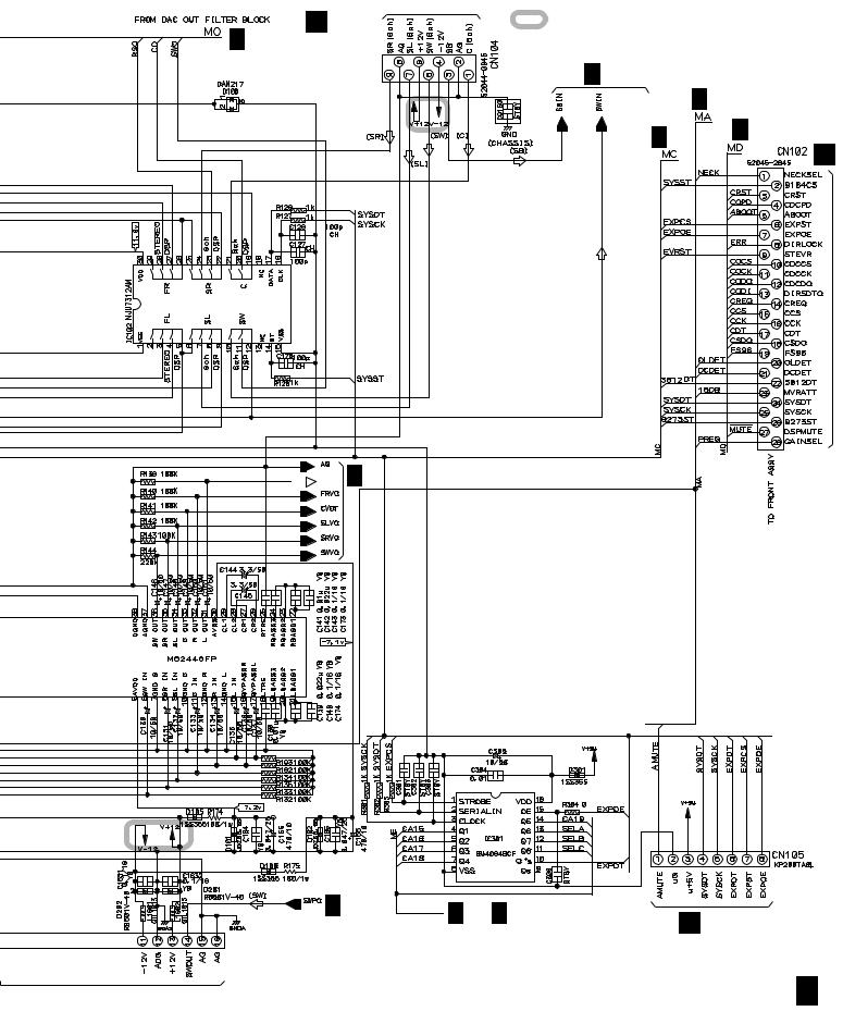
3.4 D.D & INPUT(2/4) ASSY
A
A 1/4 |
J CN1901 |
B
A 1/4 
C |
|
|
A 3/4 |
D |
|
E |
A 1/4 |
|
|
|
A 3/4 |
A 1/4


 A 4/4
A 4/4
F
A 2/4 D.D & INPUT ASSY (XWX3044)
A2/4
18 |
|
VSX-D511-K |
|
|
1 |
2 |
|
3 |
4 |

5 |
6 |
7 |
8 |
A
A 1/4 |
A 1/4
A 1/4 
CN254
H
B
C
D
A 1/4
A 1/4
E
F
A 2/4
|
|
|
|
|
|
|
|
|
VSX-D511-K |
7 |
19 |
||
5 |
6 |
|
|
|
8 |
|

1 |
2 |
3 |
4 |
3.5 D.D & INPUT(3/4) ASSY |
|
|
|
A |
|
|
|
B |
|
|
|
C |
|
|
|
D |
|
|
|
E |
|
|
|
|
|
|
A 1/4 |
F
A3/4
20 |
|
VSX-D511-K |
|
|
1 |
2 |
|
3 |
4 |
5 |
6 |
7 |
8 |
A
A 2/4 |
B
C
A 1/4 |
D |
|
E
A |
3/4 D.D & INPUT ASSY |
A |
2/4 |
|
|||
|
(XWX3044) |
|
|
F
A 3/4
|
|
|
|
|
|
|
|
|
VSX-D511-K |
7 |
21 |
||
5 |
6 |
|
|
|
8 |
|

1 |
2 |
3 |
4 |
3.6 D.D & INPUT(4/4) ASSY
A
A 2/4
B
C
D
E
F
A4/4
22
1
A 1/4 |
A 4/4 D.D & INPUT ASSY |
|
(XWX3044) |
A 1/4
A 1/4 

A 1/4 
VSX-D511-K
2 |
|
3 |
4 |

5 |
6 |
7 |
8 |
A
A 1/4 
B
C
D
E
F
A 4/4
|
|
|
|
|
|
|
|
|
VSX-D511-K |
7 |
23 |
||
5 |
6 |
|
|
|
8 |
|

1 |
2 |
3 |
4 |
3.7 AMP & PRIMARY(1/2), TRANS2 and TRANS3 ASSYS |
|
||
A |
|
|
|
|
B 1/2 AMP&PRIMARY ASSY (XWZ3533) |
|
|
B |
|
|
|
C |
|
|
|
CN253 |
|
|
|
H |
|
|
|
D |
|
|
|
E |
|
|
|
F |
|
|
|
B 1/2 |
|
|
B 2/2 |
24 |
VSX-D511-K |
|
|
1 |
2 |
3 |
4 |
Loading...