


VSXD-307
AUDIO/VIDEO MULTI-CHANNEL RECEIVER
VSX-D307
THIS MANUAL IS APPLICABLE TO THE FOLLOWING MODEL(S) AND TYPE(S).
Type
KUXJ AC120V
KUXJI AC120V
KCXJI AC120V
Model
VSX-D307
Power Requirement Remarks
ORDER NO.
RRV1925
CONTENTS
1. SAFETY INFORMATION ...................................... 2
2. EXPLODED VIEWS AND PARTS LIST................ 3
3. SCHEMATIC DIAGRAM ....................................... 8
4. PCB CONNECTION DIAGRAM.......................... 24
5. PCB PARTS LIST ............................................... 30
6. ADJUSTMENT .................................................... 35
PIONEER ELECTRONIC CORPORATION 4-1, Meguro 1-Chome, Meguro-ku, Tokyo 153-8654, Japan
PIONEER ELECTRONICS SERVICE, INC. P.O. Box 1760, Long Beach, CA 90801-1760, U.S.A.
PIONEER ELECTRONIC (EUROPE) N.V. Haven 1087, Keetberglaan 1, 9120 Melsele, Belgium
PIONEER ELECTRONICS ASIACENTRE PTE. LTD. 501 Orchard Road, #10-00 Lane Crawford Place, Singapore 0923
c
PIONEER ELECTRONIC CORPORATION 1998
7. GENERAL INFORMATION ................................ 36
7.1 PARTS ......................................................... 36
7.1.1 IC .......................................................... 36
7.1.2 DISPLAY............................................... 38
7.2 DISASSEMBLY ........................................... 39
7.3 DIAGNOSIS................................................. 41
7.4 BLOCK DIAGRAM....................................... 42
8. PANEL FACILITIES AND SPECIFICATIONS.. 44
T - IZM MAR. 1998 Printed in Japan
VSX-D307
1. SAFETY INFORMATION
This service manual is intended for qualified service technicians ; it is not meant for the casual do-ityourselfer. Qualified technicians have the necessary test equipment and tools, and have been trained
to properly and safely repair complex products such as those covered by this manual.
Improperly performed repairs can adversely affect the safety and reliability of the product and may
void the warranty. If you are not qualified to perform the repair of this product properly and safely, you
should not risk trying to do so and refer the repair to a qualified service technician.
WARNING
Lead in solder used in this product is listed by the California Health and Welfare agency as a known reproductive toxicant which may
cause birth defects or other reproductive harm (California Health & Safety Code, Section 25249.5).
When servicing or handling circuit boards and other components which contain lead in solder, avoid unprotected skin contact with
the solder. Also, when soldering do not inhale any smoke or fumes produced.
NOTICE
(FOR CANADIAN MODEL ONLY)
Fuse symbols (fast operating fuse) and/or (slow operating fuse) on PCB indicate that replacement parts must
be of identical designation.
REMARQUE
(POUR MODÈLE CANADIEN SEULEMENT)
Les symboles de fusible (fusible de type rapide) et/ou (fusible de type lent) sur CCI indiquent que les pièces
de remplacement doivent avoir la même désignation.
(FOR USA MODEL ONLY)
1. SAFETY PRECAUTIONS
The following check should be performed for the
continued protection of the customer and service
technician.
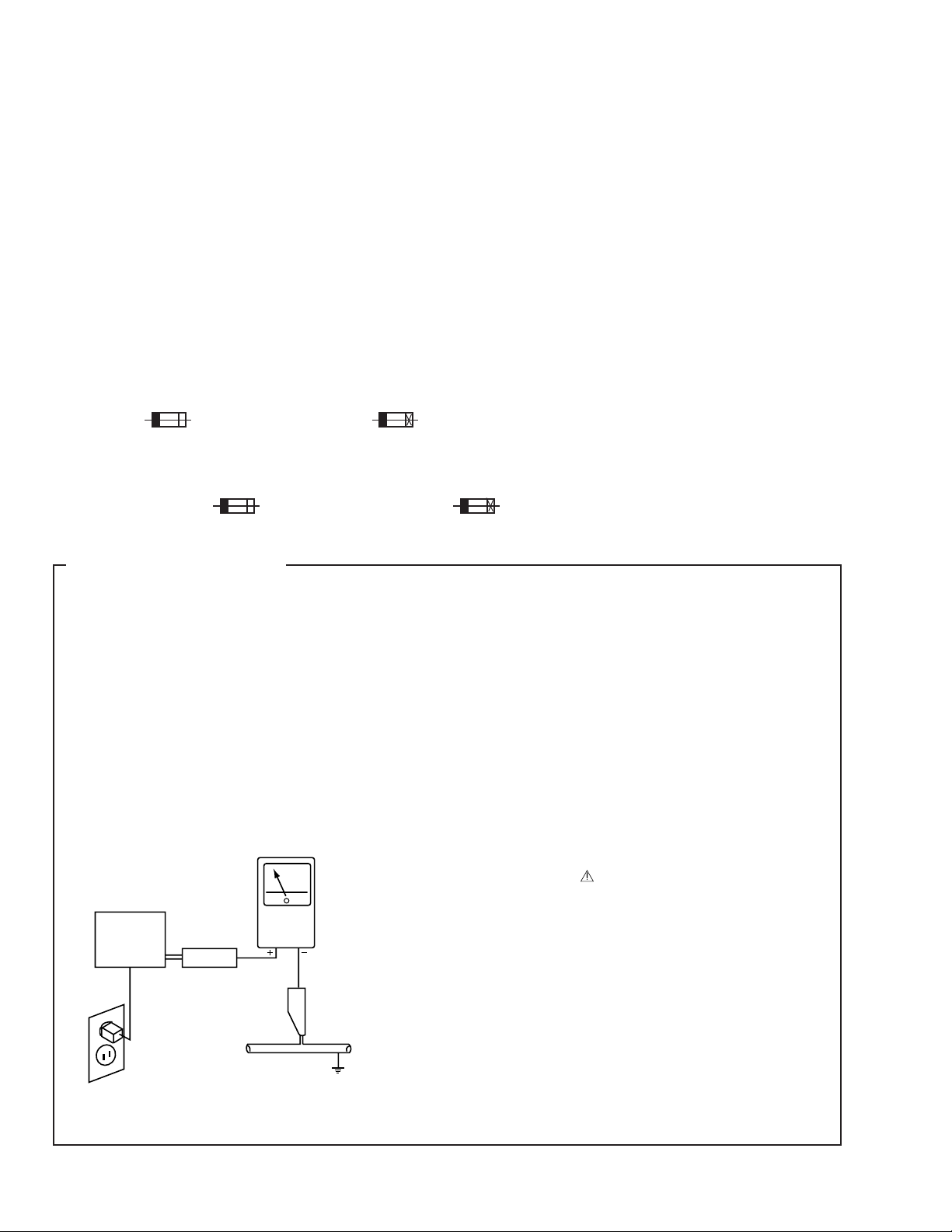
LEAKAGE CURRENT CHECK
Measure leakage current to a known earth ground (water
pipe, conduit, etc.) by connecting a leakage current tester
such as Simpson Model 229-2 or equivalent between the
earth ground and all exposed metal parts of the appliance
(input/output terminals, screwheads, metal overlays, control
shaft, etc.). Plug the AC line cord of the appliance directly
into a 120V AC 60Hz outlet and turn the AC power switch
on. Any current measured must not exceed 0.5mA.
Reading should
not be above
0.5mA
Earth
ground
Device
under
test
Also test with
plug reversed
(Using AC adapter
plug as required)
Leakage
current
tester
Test all
exposed metal
surfaces
ANY MEASUREMENTS NOT WITHIN THE LIMITS
OUTLINED ABOVE ARE INDICATIVE OF A POTENTIAL
SHOCK HAZARD AND MUST BE CORRECTED BEFORE
RETURNING THE APPLIANCE TO THE CUSTOMER.
2. PRODUCT SAFETY NOTICE
Many electrical and mechanical parts in the appliance
have special safety related characteristics. These are
often not evident from visual inspection nor the protection
afforded by them necessarily can be obtained by using
replacement components rated for voltage, wattage, etc.
Replacement parts which have these special safety
characteristics are identified in this Service Manual.
Electrical components having such features are identified
by marking with a
in this Service Manual.
The use of a substitute replacement component which does
not have the same safety characteristics as the PIONEER
recommended replacement one, shown in the parts list in
this Service Manual, may create shock, fire, or other hazards.
Product Safety is continuously under review and new
instructions are issued from time to time. For the latest
information, always consult the current PIONEER Service
Manual. A subscription to, or additional copies of, PIONEER
Service Manual may be obtained at a nominal charge from
PIONEER.
on the schematics and on the parts list
AC Leakage Test
2
2. EXPLODED VIEWS AND PARTS LIST
NOTES:• Parts marked by "NSP" are generally unavailable because they are not in our Master Spare Parts List.
The mark found on some component parts indicates the importance of the safety factor of the part.
•
Therefore, when replacing, be sure to use parts of identical designation.
Screws adjacent to mark on the product are used for disassembly.
•
VSX-D307
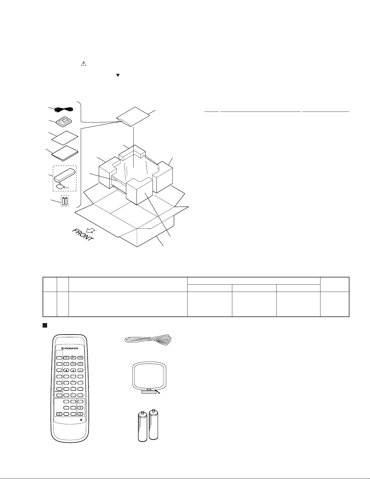
2.1 PACKING
(1) PACKING PARTS LIST
1
12
2
4
3
8 (1/2)
5
10
8 (2/2)
9 (2/2)
6
7
9 (1/2)
11
(2) CONTRAST TABLE
VSX-D307/KUXJ, KUXJI and KCXJI are constructed the same except for the following :
Mark No. Symbol and Description
3 Operating Instructions (English) ARB7136 ARB7136 Not used
3 Operating Instructions (English/French) Not used Not used ARE7159
NSP 4 Warranty Card ARY1051 ARY1051 ARY1075
11 Packing Case AHD7595 AHD7557 AHD7582
Mark No. Description Part No.
1 FM Antenna ADH7004
2 AM Loop Antenna ATB7009
3 Operating Instructions See Contrast table (2)
NSP 4 Warranty Card See Contrast table (2)
5 Remote Control Unit AXD7161
(CU-VSX124)
6 Battery Cover RZN1156
NSP 7 Dry Cell Battery (R6P, AA) VEM-013
8 Left Pad AHA7203
9 Right Pad AHA7204
10 Packing Sheet AHG1218
11 Packing Case See Contrast table (2)
12 Polyethylene Bag Z21-038
(0.03×230×340)
Part No.
VSX-D307/KUXJ VSX-D307/KUXJI VSX-D307/KCXJI
Remarks
Accessories
SOURCE
SELECT
CHANNEL
STATION
STANDBY/ON
CD
TV FUNC.
TV VOL.
TAPE
BAND
FREQ.
TUNER MPX
CLASS
D.ACCESS
DVD
123
TEST
REAR
TONE
LD
LEVEL
456
CENTER
CENTER
TV
LEVEL
MODE
CONTROL
789
CD DISC
DELAY
RECEIVER
STANDBY/ON
PRO LOGIC
VIRTUAL
EFFECT
TIME
0
DSP MODE
MUTING
LOUD.
MASTER
VOLUME
DIRECTFUNC.
SURROUND
AV MULTI-CHANNEL RECEIVER
REMOTE CONTROL UNIT
Remote Control Unit
(CU-VSX124 : AXD7161)
FM Antenna : ADH7004
AM Loop Antenna : ATB7009
Dry Cell Battery : VEM-013
(size “AA” IEC R6P) × 2
3
VSX-D307
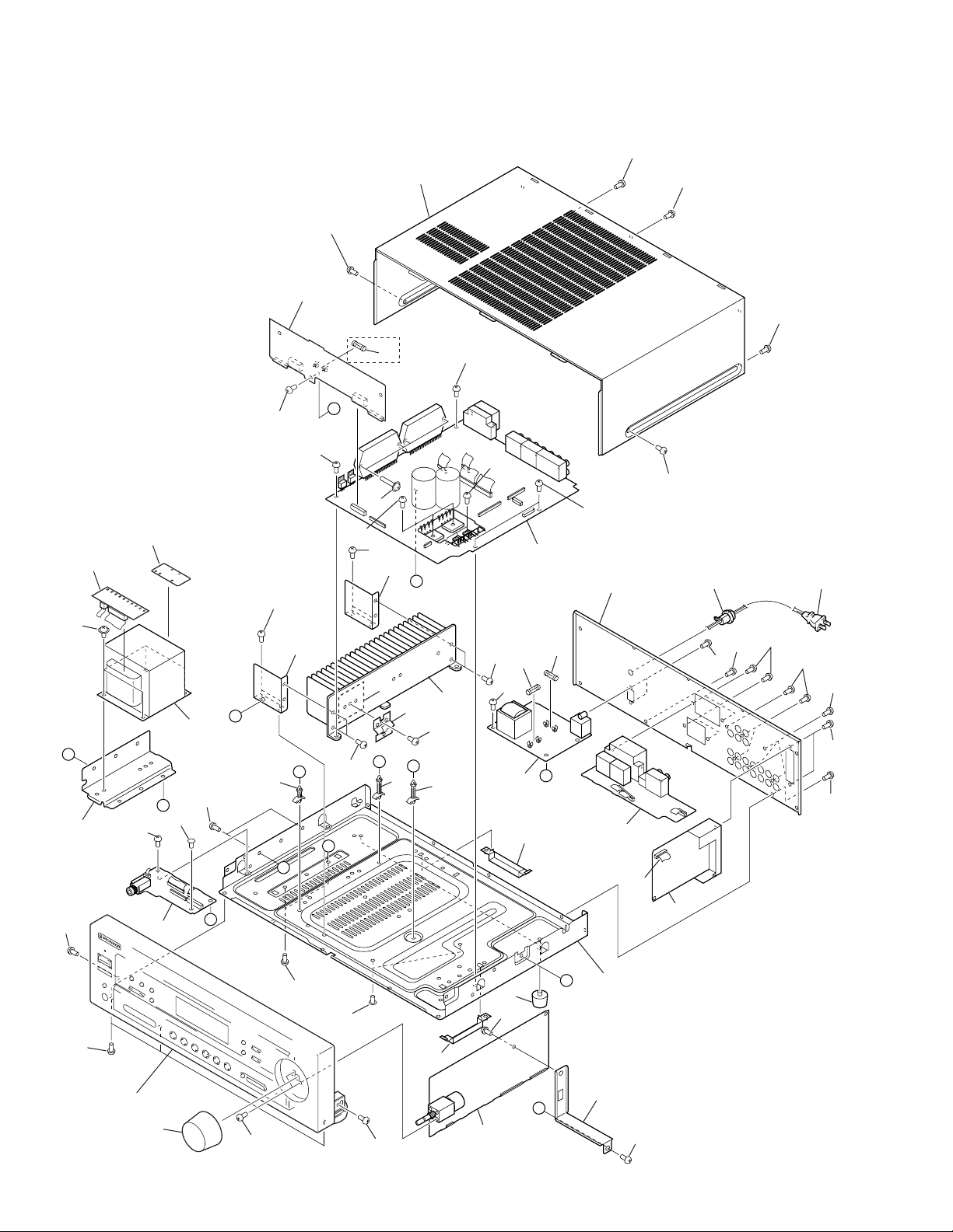
2.2 EXTERIOR SECTION
34
18
34
34
3
34
KCXJI Type
32
Only
34
35
A
19
34
D
34
34
34
36
5
6
34
34
20
1
E
34
17
14 13
34
34
34
34
34
34
10
20
28
D
22
23
34
34
11
12
34
34
F
24
E
24
F
7
34
Accessory of
Front Panel
8
34
34
C
26
34
B
27
B
A
15
34
4
C
34
Refer to
"2.3 FRONT PANEL SECTION".
33
4
34
34
27
34
29
9
G
16
30
25
21
G
2
34
(1) EXTERIOR SECTION PARTS LIST
VSX-D307
Mark No. Description Part No.
1 MOTHER Assy See Contrast table (2)
2 VOLUME DSP Assy AWX7064
NSP 3 CONNECTION Assy See Contrast table (2)
4 HEADPHONE Assy AWX7066
NSP 5 TRANS 1 Assy AWX7070
NSP 6 TRANS 2 Assy AWX7071
7 PRIMARY Assy AWX7067
8 FRONT SPEAKER Assy AWX7068
9 FM/AM TUNER Unit AXX7046
10 Power Transformer ATS7205
(T1 : AC120V)
11 Fuse (FU2 : 8A) REK1086
12 Fuse (FU1 : 10A) REK1087
13 AC Power Cord PDG1057
14 Cord Stopper CM-22C
15 Flexible Cable 13P (J32) ADD7081
(MOTHER CN110-FM/AM TUNER Unit)
NSP 16 Under Base ANA7067
17 Rear Panel See Contrast table (2)
18 Bonnet Case AZN7710
19 T Angle ANG7178
20 H Angle ANG7179
Mark No. Description Part No.
21 PCB Angle ANG7180
22 FET Angle ANG7186
NSP 23 Heat Sink ANH7075
24 PCB Support AEC7006
25 Push Rivet AEC7025
26 PCB Support AEC7132
27 Card Spacer AEC7133
28 Mica Sheet AEE7026
29 Screw Cover AMR7199
30 Foot Assy REC1263
31 • • • • •
32 Fuse (FU91 : 10A) See Contrast table (2)
33 Round Knob AAB7082
34 Screw BBZ30P080FZK
35 Screw ABA7044
36 Screw ABA7043
(2) CONTRAST TABLE
VSX-D307/KUXJ, KUXJI and KCXJI are constructed the same except for the following :
Mark No. Symbol and Description
1 MOTHER Assy AWX7058 AWX7058 AWX7177
NSP 3 CONNECTION Assy AWX7060 AWX7060 AWX7176
17 Rear Panel ANC7663 ANC7627 ANC7691
32 Fuse (FU91 : 10A) Not used Not used REK1087
VSX-D307/KUXJ VSX-D307/KUXJI VSX-D307/KCXJI
Part No.
Remarks
5
VSX-D307
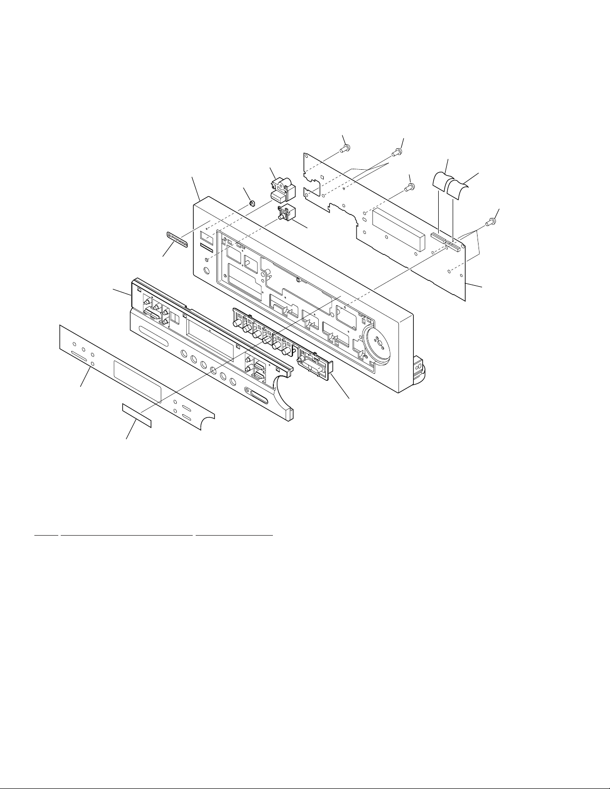
2.3 FRONT PANEL SECTION
12
5
11
8
6 (2/2)
7
10
9
6 (1/2)
12
12
3
2
12
1
4
(1) FRONT PANEL SECTION PARTS LIST
Mark No. Description Part No.
1 FRONT Assy AWX7062
2 Flexible Cable 20P (J31) ADD7083
(MOTHER CN109-FRONT CN501)
3 Flexible Cable 20P (J35) ADD7083
(MOTHER CN111-FRONT CN502)
NSP 4 Getter AAX7631
5 Power Button AAD7440
6 Function Button AAD7441
7 PIONNER Badge PAM1755
8 LED Lens PNW2019
9 Sheet AAK7539
10 Sub Panel AAP7040
11 Front Panel AMB7494
12 Screw BPZ30P080FMC
6

VSX-D307
7
1
23
4
VSX-D307
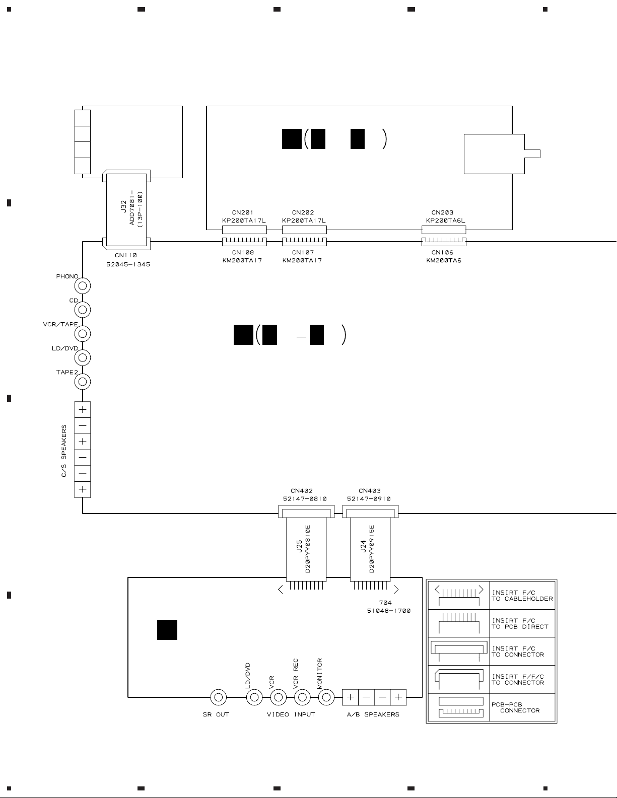
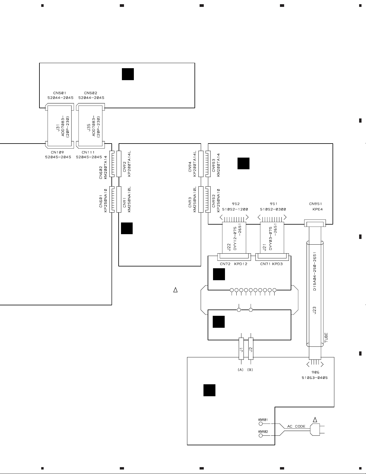
3. SCHEMATIC DIAGRAM
3.1 OVERALL CONNECTION DIAGRAM
Note : When ordering service parts, be sure to refer to "EXPLODED VIEWS and P AR TS LIST" or "PCB PARTS LIST".
A
FM/AM
TUNER UNIT
(AXX7046)
B
E
E
1/2E2/2
,
VOLUME DSP ASSY
(AWX7064)
A
A
1/3
A
3/3
MOTHER ASSY
(AWX7058 : KUXJ,KUXJI)
(AWX7177 : KCXJI)
C
FRONT SPEAKER ASSY
F
(AWX7068)
D
8
1234
5
678
VSX-D307
A
D
FRONT ASSY
(AWX7062)
G
B
CONNECTION ASSY
(AWX7060:KUXJ,KUXJI)
(AWX7176:KCXJI)
!
T1
POWER
TRANSFORMER
ATS7205
HEADPHONE ASSY
(AWX7066)
TRANS 2 ASSY
C
(AWX7071)
TRANS 1 ASSY
I
(AWX7070)
B
C
PRIMARY ASSY
H
(AWX7067)
D
!
AC120V
60Hz
AC POWER CORD
PDG1057
9
5
6
7
8

1
VSX-D307
3.2 MOTHER ASSY (1/3)
23
4
A
A
MOTHER ASSY
1/3
(AWX7058:KUXJ,KUXJI)
IC151:
PHONO RIAA AMP
(AWX7177:KCXJI)
B
IC101:
CN102(1/2)
AKB7015
FUNCTION
SW
CN102(2/2)
IC102:
BUFFER AMP
C
D
10
: AUDIO SIGNAL ROUTE
(C)
: AUDIO SIGNAL ROUTE (CENTER)
(S)
: AUDIO SIGNAL ROUTE (SURROUND)
1/3
A
1234

5
678
VSX-D307
A
CN201
E
1/2
E
1/2
CN202
(C)
(S)
A
2/3
B
A
2/3
CN501
D
MTZJ5.1B
Q191:
RIPPLE
FILTER
FOR TUNER
TO FM/AM TUNER UNIT
1/50
A
3/3
A
2/3
C
A
2/3
CN502
D
A
3/3
D
1/3
A
5
6
7
8
11
1
VSX-D307
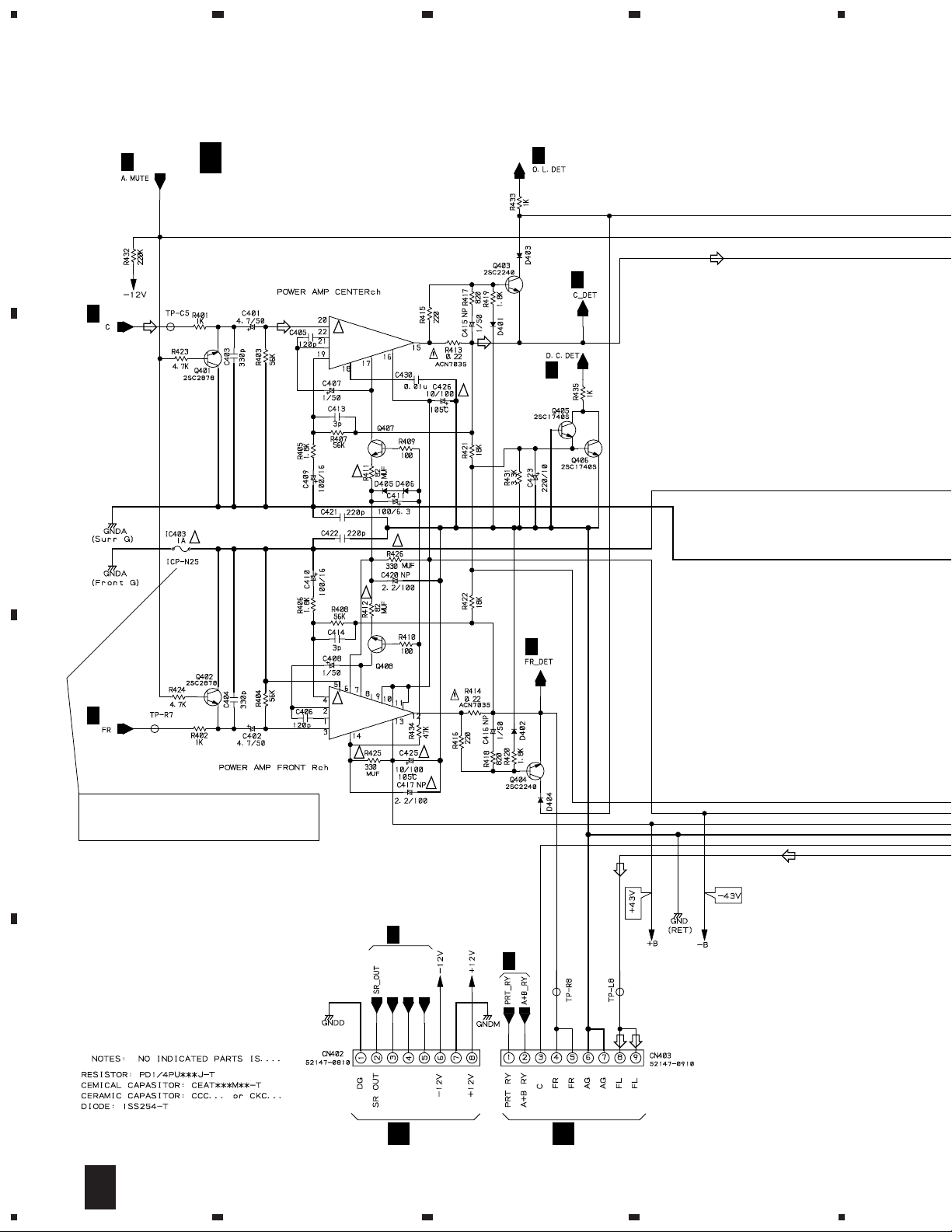
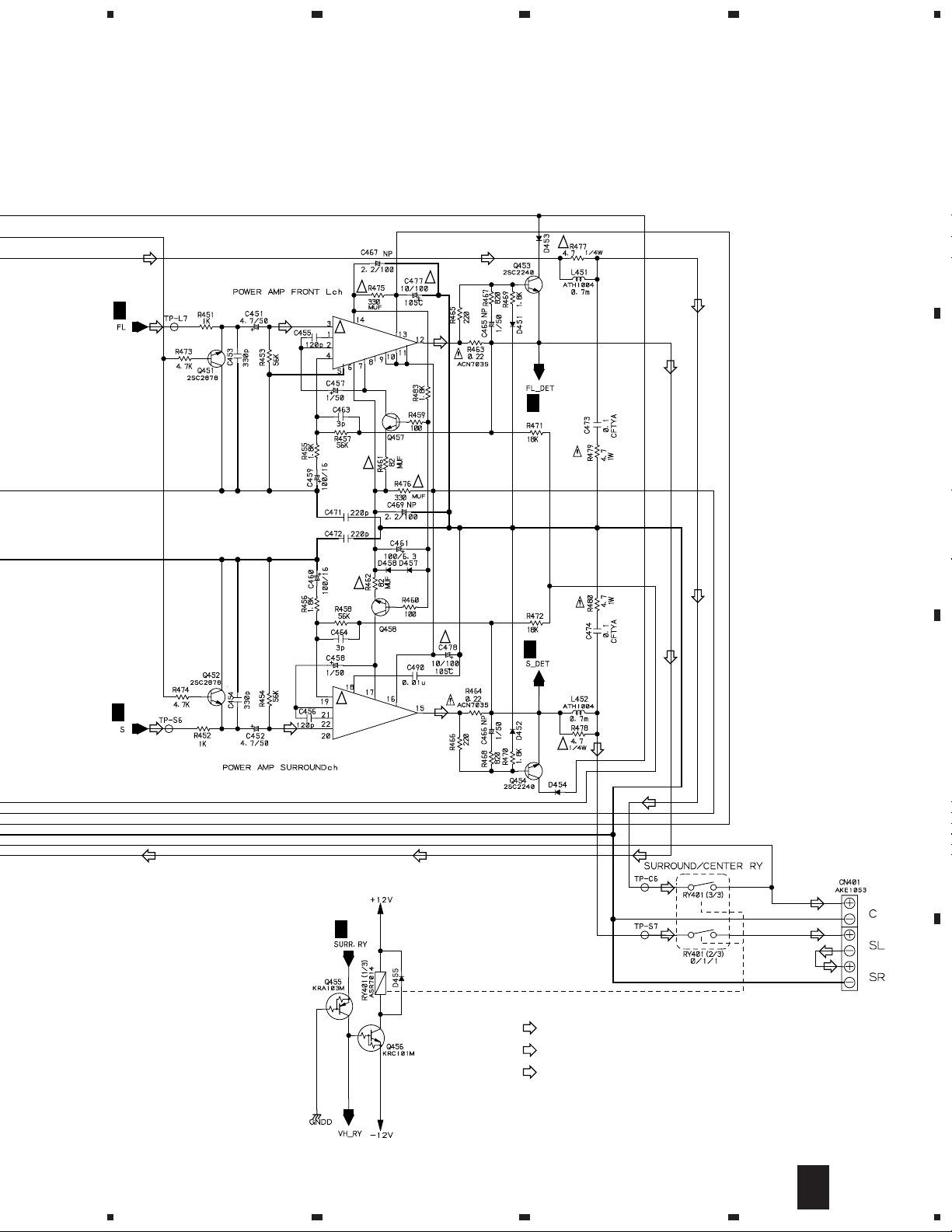
3.3 MOTHER ASSY (2/3)
A
A
1/3
A
1/3
(C)
A
23
MOTHER ASSY
2/3
(AWX7058:KUXJ,KUXJI)
(AWX7177:KCXJI)
(C)
!
IC401(2/2)
PAC007A
2SC2705
4
A
1/3
(C)
A
3/3
(C)
A
1/3
!
B
!
A
1/3
C
CAUTION : FOR CONTINUED PROTECTION AGAINST
RISK OF FIRE. REPLACE ONLY WITH
SAME TYPE NO. ICP-N25, MFD BY ROHM
CO., LTD. FOR IC403.
!
!
!
IC401(1/2)
PAC007A
!
2SC2705
!
A
3/3
!
!
A
1/3
A
1/3
V CONT B
V MUTE
V CONT A
D
12
V MUTE
V CONT B
F
2/3
A
1234
V CONT A
J25
VIDEO G
F
J24
5
678
VSX-D307
A
(C) (C)
!
A
1/3
!
IC402(1/2)
PAC007A
!
!
2SC2705
!
2SC2705
!
!
(C)
A
3/3
B
(C)
!
A
3/3
!
A
1/3
(S)
(S)
IC402(2/2)
PAC007A
(S)
!
(S)
C
(C)
(C)
A
1/3
: AUDIO SIGNAL ROUTE
(C)
: AUDIO SIGNAL ROUTE (CENTER)
(S)
: AUDIO SIGNAL ROUTE (SURROUND)
(S)
(C)
(S)
(S)
(S)
D
2/3
A
5
6
7
8
13
1
23
VSX-D307
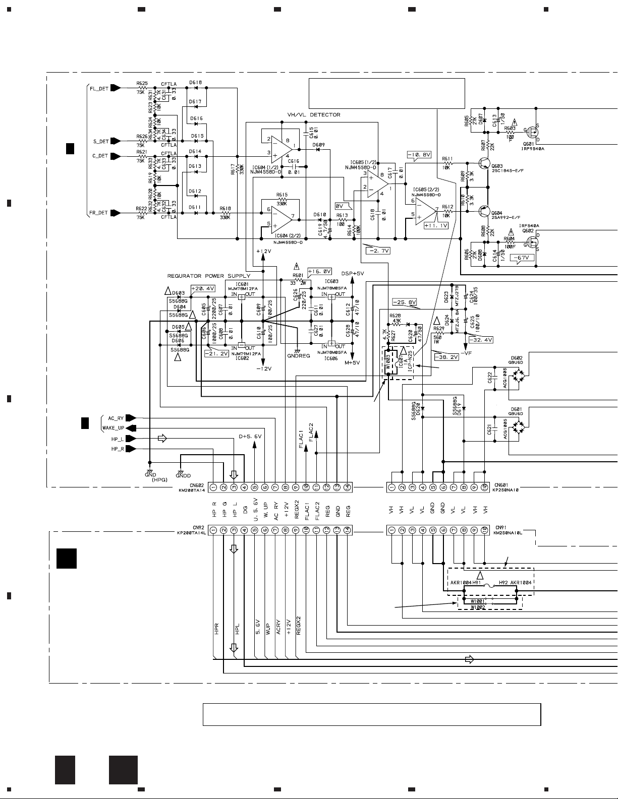
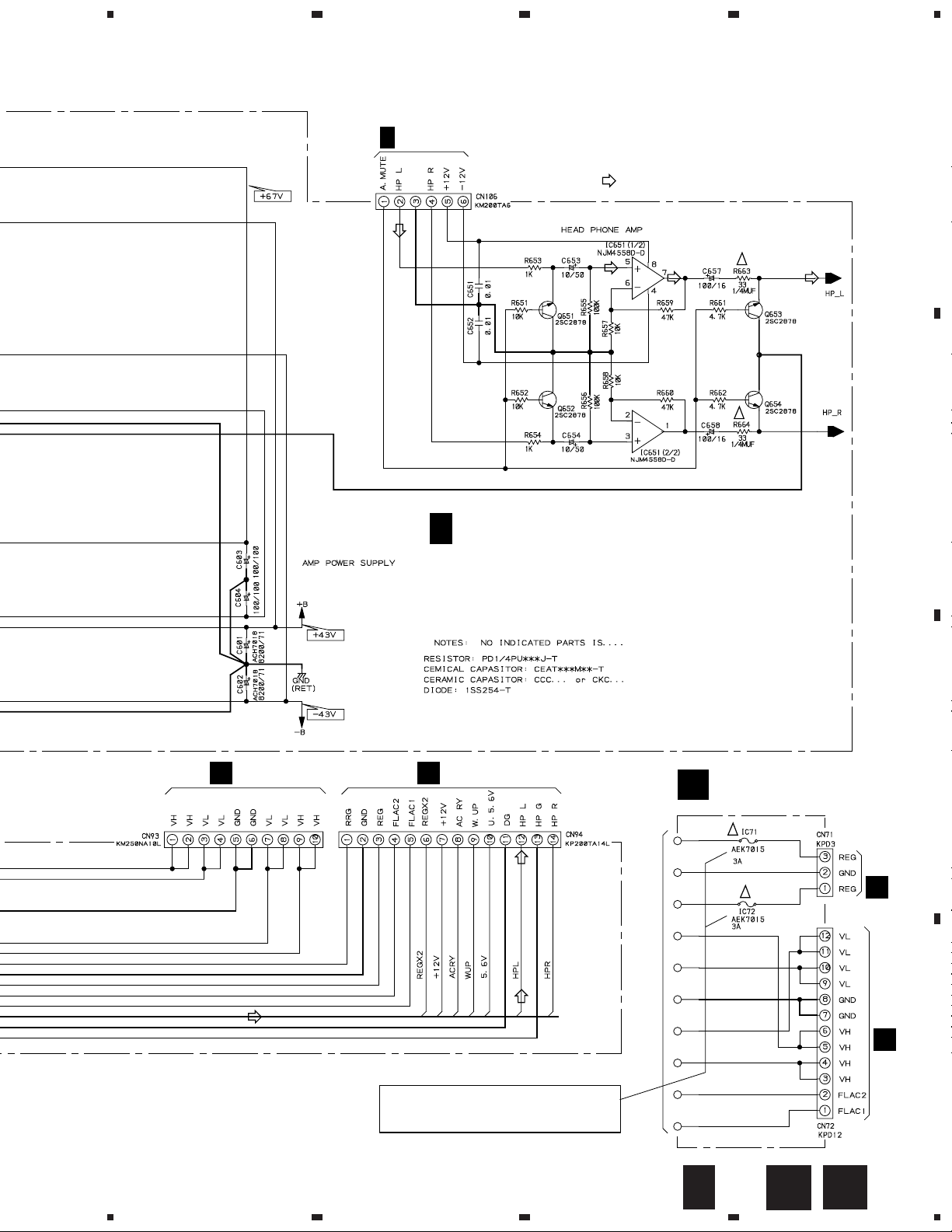
3.4 MOTHER (3/3), CONNECTION AND TRANS 2 ASSEMBLIES
CAUTION : FOR CONTINUED PROTECTION AGAINST
RISK OF FIRE. REPLACE ONLY WITH
SAME TYPE NO. ICP-N25, MFD BY ROHM
A
A
2/3
!
B
!
!
CO., LTD. FOR IC607.
D625
MTZJ16B
4
MTZJ18B MTZJ18B
!
!
KUXJ,
A
1/3
C
(HP)
(HP)(HP)(HP)
KUXJI
ONLY
!
KCXJI
ONLY
0.01/250
0.01/250
KCXJI ONLY
B
FU91
!
CONNECTION ASSY
(AWX7060:KUXJ,KUXJI)
(AWX7176:KCXJI)
KUXJ,KUXJI
ONLY
10A
REK1087
(HP)
D
• NOTE FOR FUSE REPLACEMENT
CAUTION -
FOR CONTINUED PROTECTION AGAINST RISK OF FIRE.
REPLACE ONLY WITH SAME TYPE AND RATINGS ONLY.
14
3/3
A
1234
B
5
678
VSX-D307
CN203
1/2
E
A
(HP)
HP G
(HP)
: AUDIO SIGNAL ROUTE (HEADPHONE)
A
(HP)
MOTHER ASSY
3/3
(AWX7058:KUXJ,KUXJI)
(AWX7177:KCXJI)
(HP)
!
!
(HP)
B
G
5
CN952
(HP)
CN953
G
(HP)(HP)
CAUTION : FOR CONTINUED PROTECTION AGAINST
RISK OF FIRE. REPLACE ONLY WITH
SAME TYPE NO. 491003 MFD, BY
LITTELFUSE INK. FOR IC71,IC72.
6
TRANS 2 ASSY
C
(AWX7071)
!
!
T1 POWER TRANSFORMER
3/3
A
7
B
C
8
C
J21
G
J22
G
D
15
1
VSX-D307
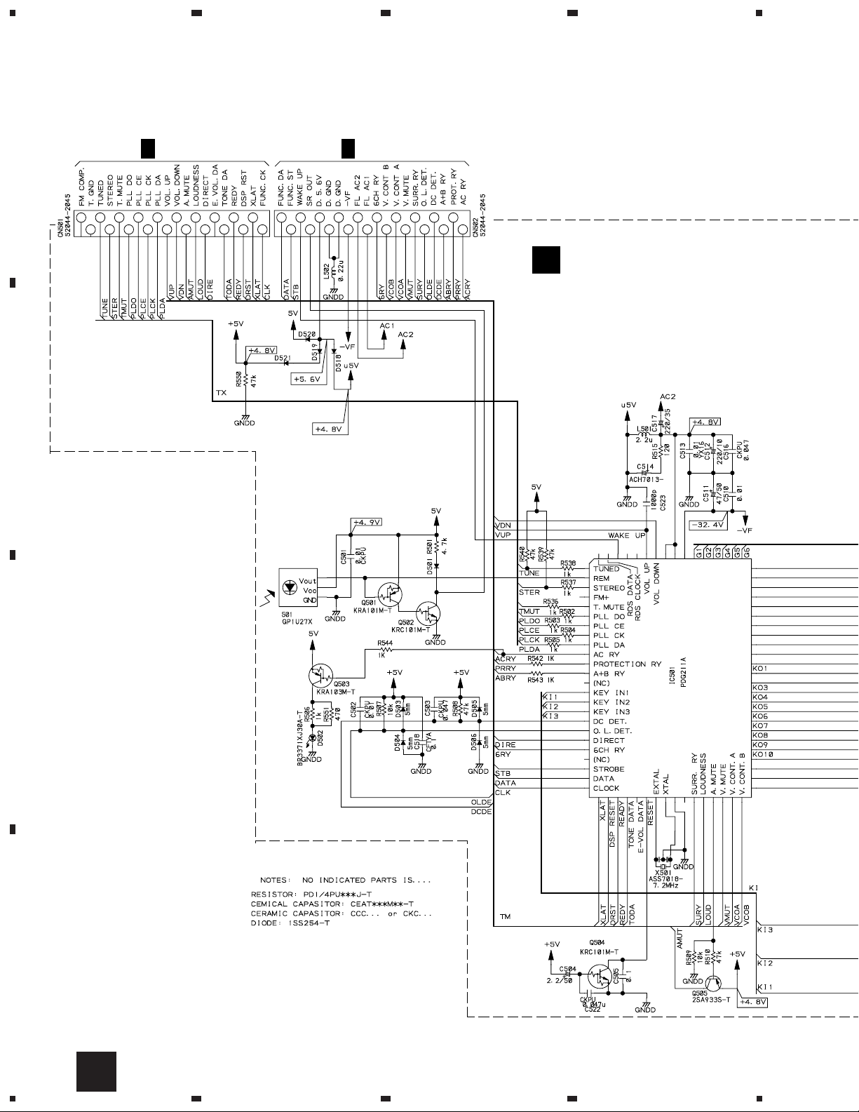
3.5 FRONT ASSY
23
4
A
5
3
1
6
4
2
CN109
1/3
A
5
3
9
7
11
8
12
10
171915
13
16
14
1
20
18
6
4
2
CN111
1/3
A
9
7
11
8
12
10
171915
13
14
20
18
16
FRONT ASSY
D
(AWX7062)
B
REMOTE
RECEIVER
UNIT
C
STANDBY
IND.
D
16
D
1234
 Loading...