


 Loading...
STANDBY/ON |
|
2DIGITAL |
DTS |
AUTO |
STEREO 2PRO LOGICII ADVANCED PHONES SOUND MODE |
MASTER |
|
INPUT SELECTOR VOLUME |
|||||
|
FRONT INPUT |
|
|
|
|
|
|
VIDEO |
L AUDIO R |
|
|
|
|
PHONES |
DIGITAL IN |
|
|
|
|
|
DOWN |
UP |
VSX-C301-S
ORDER NO.
RRV2753
AUDIO/VIDEO MULTI-CHANNEL RECEIVER
VSX-C301-S
THIS MANUAL IS APPLICABLE TO THE FOLLOWING MODEL(S) AND TYPE(S).
Model |
Type |
Power Requirement |
Remarks |
|
|
|
|
VSX-C301-S |
KUCXU |
AC120V |
|
|
|
|
|
For details, refer to "Important symbols for good services".
PIONEER CORPORATION 4-1, Meguro 1-chome, Meguro-ku, Tokyo 153-8654, Japan
PIONEER ELECTRONICS (USA) INC. P.O. Box 1760, Long Beach, CA 90801-1760, U.S.A.
PIONEER EUROPE NV Haven 1087, Keetberglaan 1, 9120 Melsele, Belgium
PIONEER ELECTRONICS ASIACENTRE PTE. LTD. 253 Alexandra Road, #04-01, Singapore 159936
 PIONEER CORPORATION 2003
T-ZZK MAY 2003 printed in Japan

1 |
2 |
3 |
4 |
SAFETY INFORMATION
A
This service manual is intended for qualified service technicians; it is not meant for the casual do-it-yourselfer. Qualified technicians have the necessary test equipment and tools, and have been trained to properly and safely repair complex products such as those covered by this manual.
Improperly performed repairs can adversely affect the safety and reliability of the product and may void the warranty. If you are not qualified to perform the repair of this product properly and safely, you should not risk trying to do so and refer the repair to a qualified service technician.
WARNING
BThis product contains lead in solder and certain electrical parts contain chemicals which are known to the state of California to cause cancer, birth defects or other reproductive harm.
Health & Safety Code Section 25249.6 – Proposition 65
NOTICE
(FOR CANADIAN MODEL ONLY)
Fuse symbols  (fast operating fuse) and/or
  (slow operating fuse) on PCB indicate that replacement parts must be of identical designation.
REMARQUE
(POUR MODÈLE CANADIEN SEULEMENT)
C Les symboles de fusible  (fusible de type rapide) et/ou
  (fusible de type lent) sur CCI indiquent que les pièces de remplacement doivent avoir la même désignation.
(FOR USA MODEL ONLY)
1. SAFETY PRECAUTIONS
The following check should be performed for the continued protection of the customer and ser vice technician.
LEAKAGE CURRENT CHECK
Measure leakage current to a known earth ground (water pipe, conduit, etc.) by connecting a leakage
Dcurrent tester such as Simpson Model 229 - 2 or equivalent between the earth ground and all exposed metal parts of the appliance (input/output terminals, screwheads, metal overlays, control shaft, etc.). Plug the AC line cord of the appliance directly into a 120V AC 60 Hz outlet and turn the AC power switch on. Any current measured must not exceed 0.5 mA.
|
|
|
Reading should |
|
|
Leakage |
not be above |
|
|
0.5 mA |
|
|
|
current |
|
|
|
|
|
E |
Device |
tester |
|
|
under |
|
|
|
test |
|
|
|
Test all |
|
|
|
exposed metal |
|
|
|
surfaces |
|
|
|
Also test with |
|
|
|
plug reversed |
|
|
|
(Using AC adapter |
|
Earth |
|
plug as required) |
|
ground |
AC Leakage Test
ANY MEASUREMENTS NOT WITHIN THE LIMITS OUTLINED ABOVE ARE INDICATIVE OF A POTENTIAL SHOCK HAZARD AND MUST BE CORRECTED BEFORE RETURNING THE APPLIANCE TO THE CUSTOMER.
2. PRODUCT SAFETY NOTICE
Many electrical and mechanical parts in the appliance have special safety related characteristics. These are often not evident from visual inspection nor the protection afforded by them necessarily can be obtained by using replacement components rated for voltage, wattage, etc. Replacement par ts which have these special safety characteristics are identified in this Service Manual.
Electrical components having such features are identified by marking with a  on the schematics and on the parts list in this Service Manual.
The use of a substitute replacement component which does not have the same safety characteristics as the PIONEER recommended replacement one, shown in the parts list in this Service Manual, may create shock, fire, or other hazards.
Product Safety is continuously under review and new instructions are issued from time to time. For the latest information, always consult the current PIONEER Service Manual. A subscription to, or additional copies of, PIONEER Service Manual may be obtained at a nominal charge from PIONEER.
F
|
|
|
|
|
|
|
2 |
|
VSX |
-C301 |
-S |
|
|
1 |
2 |
|
|
|
3 |
4 |

5 |
6 |
7 |
8 |
[ Important symbols for good services ]
In this manual, the symbols shown-below indicate that adjustments, settings or cleaning should be made securely. When you find the procedures bearing any of the symbols, be sure to fulfill them:
1. Product safety
You should conform to the regulations governing the product (safety, radio and noise, and other regulations), and should keep the safety during servicing by following the safety instructions described in this manual.
2. Adjustments
To keep the original performances of the product, optimum adjustments or specification confirmation is indispensable.
In accordance with the procedures or instructions described in this manual, adjustments should be performed.
3. Cleaning
For optical pickups, tape-deck heads, lenses and mirrors used in projection monitors, and other parts requiring cleaning, proper cleaning should be performed to restore their performances.
4. Shipping mode and shipping screws
A
B
To protect the product from damages or failures that may be caused during transit, the shipping mode should be set or the shipping screws should be installed before shipping out in accordance with this manual, if necessary.
5. Lubricants, glues, and replacement parts
Appropriately applying grease or glue can maintain the product performances. But improper lubrication or applying
glue may lead to failures or troubles in the product. By following the instructions in this manual, be sure to apply the

 prescribed grease or glue to proper portions by the appropriate amount.For replacement parts or tools, the prescribed ones should be used.
C
D
E
F
|
|
|
|
|
|
|
|
|
VSX |
-C301 |
-S |
7 |
3 |
5 |
6 |
|
|
|
8 |
1 2 3 4
CONTENTS
|
SAFETY INFORMATION..................................................................................................................................... |
2 |
|
A |
1. SPECIFICATIONS ............................................................................................................................................ |
5 |
|
2. EXPLODED VIEWS AND PARTS LIST |
6 |
||
|
|||
|
2.1 PACKING ................................................................................................................................................... |
6 |
|
|
2.2 EXTERIOR SECTION................................................................................................................................ |
8 |
|
|
2.3 INTERIOR SECTION ............................................................................................................................... |
10 |
|
|
2.4 FRONT PANEL SECTION ....................................................................................................................... |
12 |
|
|
3. BLOCK DIAGRAM AND SCHEMATIC DIAGRAM .......................................................................................... |
14 |
|
|
3.1 BLOCK DIAGRAM ................................................................................................................................... |
14 |
|
|
3.1.1 AUDIO AND VIDEO BLOCK ................................................................................................................. |
14 |
|
|
3.1.2 POWER SUPPLY BLOCKS .................................................................................................................. |
16 |
|
|
3.2 OVERALL WIRING DIAGRAM................................................................................................................. |
18 |
|
|
3.3 FM/AM TUNER MODULE........................................................................................................................ |
20 |
|
B |
3.4 VIDEO ASSY ........................................................................................................................................... |
22 |
|
3.5 AUDIO INPUT ASSY |
24 |
||
|
|||
|
3.6 MOTHER ASSY (1/5)............................................................................................................................... |
26 |
|
|
3.7 MOTHER ASSY (2/5) and DSP KAWA ASSY ......................................................................................... |
28 |
|
|
3.8 MOTHER ASSY (3/5)............................................................................................................................... |
30 |
|
|
3.9 MOTHER ASSY (4/5)............................................................................................................................... |
32 |
|
|
3.10 MOTHER ASSY (5/5)............................................................................................................................. |
34 |
|
|
3.11 DSP ASSY (1/2)..................................................................................................................................... |
36 |
|
|
3.12 DSP ASSY (2/2)..................................................................................................................................... |
38 |
|
|
3.13 FRONT IN and AMP KAWA ASSYS ...................................................................................................... |
40 |
|
|
3.14 6CH AMP ASSY .................................................................................................................................... |
42 |
|
|
3.15 AMP OUT ASSY .................................................................................................................................... |
44 |
|
C |
3.16 ENCODER, FRONT and POWER SW ASSYS ..................................................................................... |
46 |
|
3.17 PRIMARY, D5V, 12V and VHVL ASSYS |
48 |
||
|
|||
|
4. PCB CONNECTION DIAGRAM ..................................................................................................................... |
50 |
|
|
4.1 FM/AM TUNER MODULE........................................................................................................................ |
51 |
|
|
4.2 AUDIO INPUT and 12V ASSYS............................................................................................................... |
52 |
|
|
4.3 MOTHER, DSP KAWA and D5V ASSYS ................................................................................................. |
54 |
|
|
4.4 DSP ASSY ............................................................................................................................................... |
58 |
|
|
4.5 FRONT IN ASSY...................................................................................................................................... |
60 |
|
|
4.6 AMP KAWA ASSY ................................................................................................................................... |
61 |
|
|
4.7 6CH AMP ASSY ...................................................................................................................................... |
62 |
|
|
4.8 AMP OUT ASSY ...................................................................................................................................... |
64 |
|
|
4.9 ENCODER, FRONT and POWER SW ASSYS ....................................................................................... |
66 |
|
D |
4.10 PRIMARY ASSY .................................................................................................................................... |
70 |
|
|
4.11 VHVL ASSY ........................................................................................................................................... |
71 |
|
|
4.12 VIDEO ASSYS ....................................................................................................................................... |
72 |
|
|
5. PCB PARTS LIST ........................................................................................................................................... |
73 |
|
|
6. ADJUSTMENT ............................................................................................................................................... |
79 |
|
|
6.1 TUNER SECTION.................................................................................................................................... |
79 |
|
|
7. GENERAL INFORMATION............................................................................................................................. |
80 |
|
|
7.1 DIAGNOSIS ............................................................................................................................................. |
80 |
|
|
7.1.1 Test Mode.............................................................................................................................................. |
80 |
|
|
7.1.2 Protection Circuit................................................................................................................................... |
81 |
|
|
7.1.3 Specifications of Speaker Detection ..................................................................................................... |
82 |
|
|
7.1.4 Circuit Description................................................................................................................................. |
83 |
|
E |
7.1.5 Troubleshooting ..................................................................................................................................... |
84 |
|
|
7.1.6 Timing Chart.......................................................................................................................................... |
86 |
|
|
7.2 PARTS...................................................................................................................................................... |
90 |
|
|
7.2.1 IC .......................................................................................................................................................... |
90 |
|
|
7.2.2 DISPLAY ............................................................................................................................................... |
96 |
|
|
7.3 CLEANING............................................................................................................................................... |
97 |
|
|
8. PANEL FACILITIES ........................................................................................................................................ |
98 |
F
|
|
|
|
|
|
|
4 |
|
VSX |
-C301 |
-S |
|
|
1 |
2 |
|
|
|
3 |
4 |

5 |
6 |
1. SPECIFICATIONS
Amplifier section
Continuous average power output of 28 watts* per channel, min., at 6 ohms, from 20 Hz to 20,000 Hz with no more than 0.9 %** total harmonic distortion (front).
Continuous Power Output (STEREO mode)
Front. . . . . . . . . . . . . . . . . . . . . . . . . . . . . . . 28 W + 28 W (FTC 20–20 kHz, THD 0.9 %, 6 Ω)
RMS Power Output
Front. . . . . . . . . . . . 75 W/ch (DIN 1 kHz, THD 10 %, 6 Ω) Center . . . . . . . . . . . . .75 W (DIN 1 kHz, THD 10 %, 6 Ω)
Surround. . . . . . . . .75 W/ch (DIN 1 kHz, THD 10 %, 6 Ω)
Audio section
Input (Sensitivity/Impedance) . . . . . . . . . . 200 mV/47 kΩ Output (Level/Impedance)
DVR/VCR. . . . . . . . . . . . . . . . . . . . . . . . . 200 mV/2.2 kΩ
*Measured pursuant to the Federal Trade Commission’s Trade Regulation rule on Power Output Claims for Amplifiers.
**Measured by Audio Spectrum Analyzer.
Video section
Input (Sensitivity/Impedance) . . . . . . . . . . . . 1 Vp-p/75 Ω Output (Level/Impedance). . . . . . . . . . . . . . . 1 Vp-p/75 Ω
Manufactured under license from Dolby Laboratories. "Dolby", "Pro Logic", and the double-D symbol are trademarks of Dolby Laboratories.
"DTS" and "DTS Digital Surround" are trademarks of Digital Theater Systems, Inc.
7 |
8 |
FM tuner section
Frequency Range. . . . . . . . . . . . . . . 87.5 MHz to 108 MHz
Usable Sensitivity. . . . . Mono:13.2 dBf, IHF (1.3 µV/ 75 Ω) 50 dB Quieting Sensitivity. . . . . . . . . . . . . .Mono: 20.2 dBf Stereo: 38.6 dBf signal to noise ratio . . . . . . . . . . Mono: 76.0 dB (at 85 dBf)
Stereo: 72.0 dB (at 85 dBf)
Distortion . . . . . . . . . . . . . . . . . . . . . .Stereo: 0.6 % (1 kHz) Alternate Channel Selectivity . . . . . . . . . . .60 dB (400 kHz)
Stereo Separation. . . . . . . . . . . . . . . . . . . . . .40 dB (1 kHz)
Frequency Response . . . . . . . . . . .30 Hz to 15 kHz (±1dB) Antenna Input (DIN) . . . . . . . . . . . . . . . . .75 Ω unbalanced
AM tuner section
Frequency Range. . . . .530 kHz to 1,700 kHz (10kHz step) Sensitivity (IHF, Loop antenna). . . . . . . . . . . . . . 350 µV/m Selectivity . . . . . . . . . . . . . . . . . . . . . . . . . . . . . . . . . 30 dB Signal-to-Noise Ratio. . . . . . . . . . . . . . . . . . . . . . . . .50 dB
Antenna. . . . . . . . . . . . . . . . . . . . . . . . . . . . .Loop antenna
Miscellaneous
Power Requirements. . . . . . . . . . . . . . . .AC 120 V, 60 Hz
Power Consumption . . . . . . . . . . . . . . . . . . . . . . . . 130 W In standby. . . . . . . . . . . . . . . . . . . . . . . . . . . . . . . . . 0.3 W
Dimensions. . . . 16 9/16(W) x 2 13/16(H) x 15 1/8 (D) in. Weight (without package) . . . . . . . . . . . . . . . . .14 lb 6 oz
Furnished parts
AM loop antenna . . . . . . . . . . . . . . . . . . . . . . . . . . . . . . .1 FM wire antenna. . . . . . . . . . . . . . . . . . . . . . . . . . . . . . . .1
Dry cell batteries (AA size IEC R6P) . . . . . . . . . . . . . . . 2 Remote control unit. . . . . . . . . . . . . . . . . . . . . . . . . . . . . 1 Power cable . . . . . . . . . . . . . . . . . . . . . . . . . . . . . . . . . . .1
Coaxial cable . . . . . . . . . . . . . . . . . . . . . . . . . . . . . . . . . .1 Speaker cable labels . . . . . . . . . . . . . . . . . . . . . . . . . . . .1
Operating instructions. . . . . . . . . . . . . . . . . . . . . . . . . . . .1 Warranty card. . . . . . . . . . . . . . . . . . . . . . . . . . . . . . . . . .1
Note
•Specifications and the design are subject to possible modifications without notice, due to improvements.
A
B
C
D
 Accessories
• Power Cable
(ADG7021)
FM wire antenna (ADH7004)
AM loop antenna
(ATB7009) 


 Speaker cable labels (ARW7163)
Coaxial cable (ADE7087)
• |
Remote Control Unit |
|
|
|
|
|
|
|
|
E |
|||||||||||
|
(AXD7350) |
|
|
|
|
|
|
|
|
|
|
|
|
|
|
||||||
|
|
ROOM SYSTEM SETUP SETUP |
|
MENUDTV T.EDIT MENUTOP MENU ST ST ENTER GUIDE SEARCH |
|
|
SBVIRTUALDIMMER |
BANDRETURNEON |
|
|
|
|
|
INPUTCHANNELCHANNEL |
|
||||||
FRONT L |
SOURCERECEIVER RECEIVER |
SLEEP DVDSTB DVR/TV DIRECTAV |
INPUTVIDEOFRONT FM/AM |
SELECTCHLEVEL TEST TONE |
ADVANCED AUTO |
SOUND SIGNAL MODEDIALOG SELECT MUTE |
MASTER VOLUME |
TUNE |
AUDIO |
TUNE |
B |
DISC |
ENTER |
10 |
TVCONTROL |
RECEIVER |
|||||
|
|
|
|
|
SURROUNDSURROUND |
|
|
|
|
|
SUBTITLE |
|
|
A |
D |
|
|
|
|
VOLUME |
|
|
|
|
|
|
|
|
|
|
|
|
|
|
|
ATT RF |
D.ACCESS |
|
|
|
|
|
|
|
|
|
|
|
|
|
|
|
|
|
|
|
|
|
E |
|
|
|
|
|
|
|
|
|
|
|
|
|
|
|
|
|
|
|
|
|
MPX |
|
|
|
|
|
|
|
|
|
|
|
STEREO |
|
|
|
|
|
|
|
|
|
CLASS |
|
|
|
|
|
|
|
|
|
|
|
|
|
|
|
|
|
|
|
|
|
C |
|
|
|
|
|
|
|
|
|
|
|
|
|
|
|
|
|
|
|
|
|
DISPLAY |
|
|
|
|
|
|
FRONT L
FRONT R |
• Dry Cell Battery (R6P, AA) |
|
FRONT R |
||
(VEM1030) |
||
CENTER |
||
|
||
CENTER |
|
|
SURROUND L |
|
SURROUND L
SURROUND R
SURROUND R
F
|
|
|
|
|
|
|
|
|
VSX-C301-S |
7 |
5 |
||
5 |
6 |
|
|
|
8 |
|

1 2 3 4
2. EXPLODED VIEWS AND PARTS LIST
A
NOTES: Parts marked by "NSP" are generally unavailable because they are not in our Master Spare Parts List. |
|
The |
mark found on some component parts indicates the importance of the safety factor of the part. |
Therefore, when replacing, be sure to use parts of identical designation.  Screws adjacent to
  mark on product are used for disassembly.
 For the applying amount of lubricants or glue, follow the instructions in this manual. (In the case of no amount instructions, apply as you think it appropriate.)
2.1 PACKING
B |
1 |
2
3
4
5 |
9 |
C |
20 |
14 |
|
|
11 |
17 |
13 |
|
12 |
|
18 |
D
15
E |
16 |
19
F
|
|
|
|
|
|
|
6 |
|
VSX |
-C301 |
-S |
|
|
1 |
2 |
|
|
|
3 |
4 |
5 6 7 8
PACKING parts List
Mark No. |
Description |
Part No. |
1 |
FM Wire Antenna |
ADH7004 |
2 |
AM Loop Antenna |
ATB7009 |
> 3 |
Power Cable |
ADG7021 |
4 |
Speaker Cable Label |
ARW7163 |
5 |
Operating instructions 301 |
ARE7328 |
|
(English) |
|
6• • • • • •
7• • • • • •
8• • • • • •
NSP 9 |
Polyethylene Bag |
Z21-038 |
|
(0.03*230*340) |
|
10 |
• • • • • • |
|
11 |
Remote Control Unit |
AXD7350 |
12 |
Battery Cover |
AZA7424 |
NSP 13 |
Dry cell batteries (R6P,AA) |
VEM1030 |
NSP 14 |
Warranty Card |
ARY7045 |
15 |
Left Pad 301 |
AHA7407 |
16 |
Right Pad 301 |
AHA7408 |
17 |
Spacer |
AHB7088 |
18 |
Packing Sheet |
AHG7015 |
19 |
Packing Case |
AHD8158 |
20 |
Coaxial Cable |
ADE7087 |
A
B
C
D
E
F
|
|
|
|
|
|
|
|
|
VSX |
-C301 |
-S |
7 |
7 |
5 |
6 |
|
|
|
8 |

1 |
2 |
3 |
4 |
2.2 EXTERIOR SECTION |
|
|
|
|
|
6 |
|
A |
|
7 |
|
18
5 |
18 |
17
B
12
17
NON-CONTACT SIDE |
CONTACT SIDE |
18
|
|
Refer to |
C |
|
"2.3 INTERIOR SECTION". |
|
|
25 |
|
|
B |
|
|
20 |
|
20 |
29 |
D |
20 |
|
|
A |
|
|
|
27
E |
20 |
|
|
|
20 |
|
Refer to |
|
"2.4 FRONT PANEL SECTION". |
|
22 |
|
4 |
F |
|
18
26 |
|
|
|
18 |
|
|
|
|
|
|
|
|
|
|
|
|
|
19 |
|
18 |
|
|
|
|
18 |
8 |
|
|
|
10 |
|
|
|
|
|
|
|
|
|
|
|
|
|
|
|
|
18 |
|
28 |
|
|
A |
|
|
|
|
|
|
|
|
|
|
|
|
|
1 |
|
|
18 |
|
|
|
23 |
|
|
|
|
|
|
|
24 |
|
9 |
|
|
|
*Serial Number Label is put on |
|||
|
|
|
|
bottom of Under Base. |
||
|
|
|
22 |
|
|
|
|
|
|
I |
|
|
21 |
|
|
|
|
13 |
|
|
20 |
|
|
|
22 |
|
|
|
2 |
|
14 |
|
|
|
|
|
|
20 |
|
|
|
A |
18 |
16 |
22 |
|
|
|
3 |
|
|
|
|||
|
|
|
|
|
22 |
|
|
|
|
|
|
|
|
O |
|
|
|
|
20 |
|
|
|
|
|
15 |
|
|
20 |
|
|
|
|
|
|
|
|
|
20 |
15 |
22 |
|
|
|
|
|
|
||
14 |
|
22 |
16 |
|
|
|
|
|
|
|
|
|
|
8 |
|
VSX |
-C301 |
-S |
|
|
1 |
2 |
|
|
|
3 |
4 |
5 6 7 8
EXTERIOR SECTION parts List
Mark No. |
Description |
Part No. |
1 |
FM/AM TUNER MODULE |
AXQ7245 |
2 |
6CH AMP Assy |
AWM7786 |
3 |
D5V Assy |
AWX8224 |
NSP 4 |
AMP MODULE 6CH |
AXQ7247 |
5 |
Bonnet Case |
AZN7934 |
6 |
Label |
ARW7217 |
7 |
License Label |
ARW7220 |
8 |
Fan Cover |
AMR7446 |
9 |
Rear Panel 301SKU |
ANC8157 |
10 |
Tuner Barrier |
AEC7383 |
11 |
• • • • • • |
|
> 12 |
AC Inlet Assy |
VKP2126 |
13 |
DC Fan Motor |
AXM7025 |
14 |
Fan Plate |
ANG7462 |
15 |
FET Bracket A |
ANG7418 |
NSP 16 |
Heat Sink |
ANH7161 |
17 |
Screw |
BCZ40P060FNI |
18 |
Screw |
BBZ30P080FZK |
19 |
Screw |
PPZ30P100FZK |
20 |
Screw |
BBZ30P060FMC |
21 |
Screw |
BBZ30P300FZK |
22 |
Screw |
BBZ30P140FMC |
23 |
J1905 13P FFC/60V |
ADD7402 |
NSP 24 |
Label |
VRW1629 |
25 |
VIDEO Assy |
AWX8225 |
NSP 26 |
PCB Spacer |
AEC7156 |
NSP 27 |
Energy Star Label |
AAX7876 |
28 |
J1911 19P FFC/60V |
ADD7422 |
NSP 29 |
Binder |
ZCA-BK1 |
A
B
C
D
E
F
|
|
|
|
|
|
|
|
|
VSX |
-C301 |
-S |
7 |
9 |
5 |
6 |
|
|
|
8 |
1 |
2 |
3 |
4 |
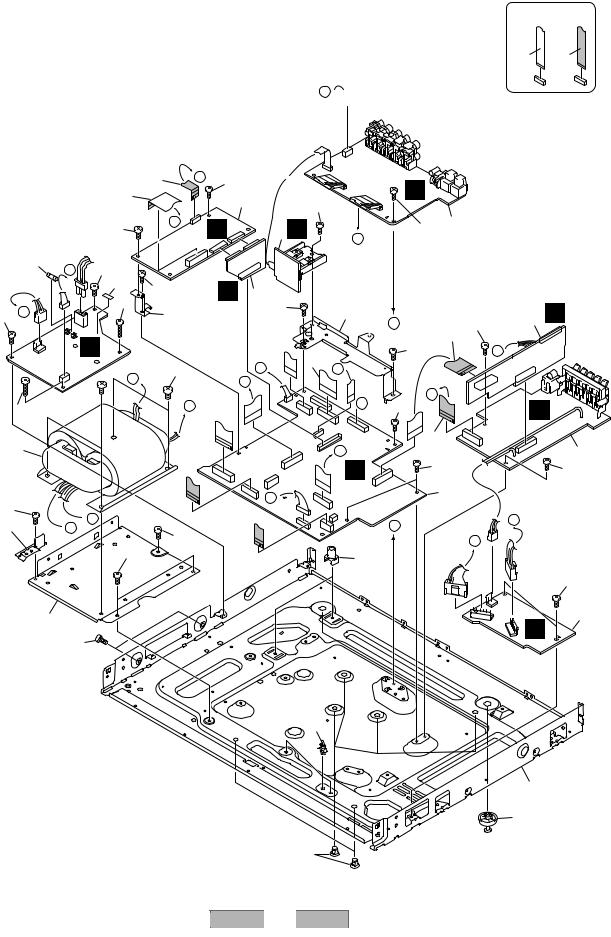
2.3 INTERIOR SECTION
A
B 

B
18
31 A
C
6 
33
19
D31
24
25
E
F
10
1
13 |
I |
31 |
|
|
|
|
|
14 |
|
4 |
31 |
|
|
||
|
|
|
|
H |
|
31 |
L |
31 |
34
31
33
22
N
32
A
32 
B
 C
C
 D
D
31
31
31
F
E
3 |
P |
M |
|
|
5
31
23
12
L I 
H
M
F
D
D 
28
27
29
VSX-C301-S
2 |
|
|
|
3 |
NON-CONTACT SIDE |
CONTACT SIDE |
C
31 1
N |
31 |
16
31
F
31
17
31
7
N
E
8 H
E 

J
9
31
C
31
10
Q
26
30
4
5 6 7 8
INTERIOR SECTION parts List
Mark No. |
Description |
Part No. |
||
|
1 |
AUDIO-INPUT Assy |
AWX8227 |
|
|
2 |
• • • • • • |
|
|
|
3 |
12V Assy |
AWX8170 |
|
|
4 |
DSP Assy |
AWX8241 |
|
|
5 |
DSP KAWA Assy |
AWX8167 |
|
|
6 |
PRIMARY Assy |
AWX8190 |
|
|
7 |
MOTHER Assy |
AWX8197 |
|
|
8 |
AMP KAWA Assy |
AWX8223 |
|
|
9 |
AMP OUT Assy |
AWX8177 |
|
|
10 |
VHVL Assy |
AWX8259 |
|
|
11 |
• • • • • • |
|
|
|
12 |
J1911 |
19P FFC/60V |
ADD7422 |
|
13 |
J1906 |
10P FFC/60V |
ADD7405 |
|
14 |
J1909 |
19P FFC/60V |
ADD7422 |
|
15 |
• • • • • • |
|
|
|
16 |
J1901 |
17P FFC/60V |
ADD7398 |
|
17 |
J1904 |
17P FFC/60V |
ADD7401 |
> |
18 |
FU1 Fuse (6.3A) |
REK1069 |
|
> |
19 |
T1 Power Transformer |
ATS7347 |
|
20• • • • • •
21• • • • • •
22 |
Core Stay A |
ANG7447 |
23 |
Core Stay B |
ANG7448 |
24 |
Jack Stay |
ANG7450 |
25 |
Trans Frame |
ANG7446 |
NSP 26 |
Under Base |
ANA7151 |
27 |
PCB Support |
AEC7365 |
28 |
PCB Mold |
AMR2533 |
NSP 29 |
PC Support |
VEC1749 |
30 |
Foot |
REC-434 |
31 |
Screw |
BBZ30P060FMC |
32 |
Screw |
BCZ40P060FNI |
33 |
Screw |
BBZ30P180FMC |
NSP 34 |
Fuse Card |
AAX2374 |
A
B
C
D
E
F
|
|
|
|
|
|
|
|
|
VSX |
-C301 |
-S |
7 |
11 |
5 |
6 |
|
|
|
8 |

1 |
2 |
3 |
4 |
2.4 FRONT PANEL SECTION
A
19
B |
7 |
8
C
10
11
D
E
F
22 |
22 |
|
22
M 2
|
|
20 |
|
|
18 |
|
22 |
|
|
|
|
|
|
|
G |
|
22 |
|
|
17 |
3 |
|
|
|
1 |
|
|
|
|
|
L |
|
22 |
|
15 |
|
|
||
|
|
|
22 |
|
|
|
16 |
|
|
|
|
21 |
|
22 |
|
|
|
|
|
|
|
6 |
|
|
5 |
|
|
|
K |
|
|
|
|
|
12 |
|
|
|
4 |
|
|
|
|
|
14 |
|
|
|
|
|
12 |
CONTACT-NON |
|
CONTACTSIDE |
13 |
|
SIDE |
||
|
10 |
|
|
|
|
|
11 |
|
|
|
|
|
|
|
|
|
12 |
|
VSX |
-C301 |
-S |
|
|
1 |
2 |
|
|
|
3 |
4 |
5 6 7 8
FRONT PANEL SECTION parts List
Mark No. |
Description |
Part No. |
1 |
FRONT IN Assy |
AWX8219 |
2 |
POWER SW Assy |
AWX8174 |
3 |
FRONT Assy |
AWX8199 |
4 |
ENCODER Assy |
AWX8175 |
5 |
Front Panel Assy |
AXG7186 |
6 |
Front Panel |
AMB7839 |
NSP 7 |
Power Button |
AAD7696 |
8 |
PIONEER Name Plate |
VAM1129 |
9 |
• • • • • • |
|
10 |
Insulator Ring |
AAK8091 |
11 |
Rubber Foot |
VEB1325 |
12 |
VOL Ring |
ABH7220 |
13 |
Volume Knob |
AAB7252 |
14 |
Select Knob |
AAB7254 |
15 |
LED Lens 301 |
AAK8084 |
16 |
J1903 9P FFC/60V |
ADD7400 |
17 |
J1902 15P FFC/60V |
ADD7399 |
18 |
J1911 19P FFC/60V |
ADD7422 |
19 |
Jack Cover |
AMR7447 |
20 |
Front Frame |
ANG7445 |
NSP 21 |
Display Window 301 |
AAK8083 |
22 |
Screw |
PPZ30P080FMC |
A
B
C
D
E
F
|
|
|
|
|
|
|
|
|
VSX |
-C301 |
-S |
7 |
13 |
5 |
6 |
|
|
|
8 |
1 |
2 |
3 |
4 |
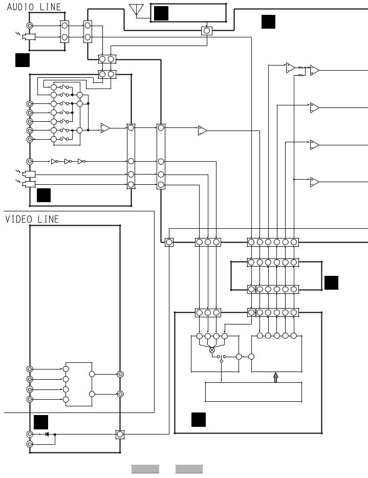
3. BLOCK DIAGRAM AND SCHEMATIC DIAGRAM
3.1 BLOCK DIAGRAM
A 3.1.1 AUDIO AND VIDEO BLOCK
|
|
|
CN1204 |
|
|
|
FM/AM TUNER |
|
|
|
|
(19P) |
|
|
|
|
A MODULE |
D MOTHER ASSY |
|||
|
CN4102 |
FRONT L |
(19P) |
|
|
|
|
|
||
FRONT L |
17 |
3 |
|
|
|
|
7 |
|||
|
|
|
|
|
|
|
|
|
|
|
DIGITAL |
8 |
F. OPT |
12 |
|
|
|
CN801(13P) |
|
|
|
|
|
|
|
|
|
|
|
|
|
|
IN |
|
|
|
|
|
|
|
|
LOW PASS FILTER |
|
|
FRONT IN |
|
3 |
8 |
CN1262 |
|
|
|
IC1101 (1/2) |
NJM4558MD |
|
|
(19P) |
|
|
|
NJM4558MD |
||||
G ASSY(1/2) |
|
|
|
|
|
|
|
IC1105 (1/2) |
||
|
|
|
|
|
|
|
3 |
2 |
||
|
FRONT L |
|
CN701 |
|
|
|
1 |
|||
|
|
|
|
|
|
|
|
2 |
1 |
|
|
|
|
3 |
8 |
(19P) |
|
|
|
|
3 |
B |
|
|
|
|
|
|
|
|
||
|
|
|
|
|
|
|
|
|
|
|
|
7 |
|
|
|
|
|
|
|
|
|
AUDIO INPUT |
8 |
9 |
|
|
|
|
|
|
|
IC1102 (1/2) |
L CH |
|
|
|
|
|
|
|
NJM4558MD |
||
|
|
|
|
|
|
|
|
|
||
DVD |
2 |
5 |
|
|
|
|
|
|
|
3 |
|
|
|
|
|
|
|
1 |
|||
TV/SAT |
3 |
|
|
|
|
|
|
|
|
2 |
|
|
|
|
|
|
IC1261 (1/2) |
|
|
||
|
|
|
|
|
CN901 |
|
CN1263 |
|
|
|
VIDEO |
4 |
|
2 |
|
|
NJM2100M |
|
|
||
|
1 |
(19P) |
INPUT L |
(19P) |
3 |
|
|
|||
|
|
|
3 |
19 |
19 |
|
|
|||
DVR/VCR |
10 |
12 |
|
|
1 |
|
IC1103 (1/2) |
|||
|
|
|
|
|
2 |
|
||||
DVR OUT |
|
|
IC702 (1/2) |
|
|
|
|
|
NJM4558MD |
|
11 |
|
|
|
|
|
|
3 |
|||
|
UPC4570G2 |
|
|
|
|
|
||||
|
|
|
|
|
|
|
|
|
|
1 |
|
IC701 NJU7312AM |
|
|
|
|
|
|
|
2 |
|
DIGITAL |
|
|
|
|
|
|
|
|
||
SELECTOR |
|
|
|
|
|
|
|
|
||
AUDIO INPUT |
|
|
|
|
|
|
|
|
||
|
|
|
|
|
COAX |
|
|
|
|
|
DVD |
|
|
|
|
11 |
11 |
|
|
|
|
|
|
|
|
|
|
|
|
|||
C |
IC901 TC7WU04F |
|
|
|
|
|
|
|
IC1103 (2/2) |
|
OPT 1 |
|
|
|
|
7 |
OPT1 |
7 |
|
|
NJM4558MD |
TV/SAT |
|
|
|
|
|
|
|
5 |
||
|
|
|
|
|
|
|
|
|
||
OPT 2 |
|
|
|
|
|
OPT2 |
|
|
|
7 |
|
|
|
|
9 |
9 |
|
|
6 |
||
DVR/VCR |
|
|
|
|
|
|
|
|||
|
|
|
|
|
|
|
|
|||
|
|
|
|
|
|
|
|
|
|
|
C AUDIO INPUT ASSY
CN9001 |
|
|
|
CN1264 |
|
|
|
|
|
|
CN1265 |
(19P) |
|
4 |
10 |
(10P) |
23 |
11 |
|
8 |
4 |
2 |
(23P) |
12 |
OPT2 |
7 |
FLO |
3 |
|||||||
SR IN/OUT |
|
OPT1 |
COAX |
F.OPT |
LIN |
SLO |
|
CO |
SWO |
||
|
|
|
|
|
|
|
|
|
|
|
D |
|
|
|
|
|
|
|
1 |
13 |
16 |
20 |
22 |
21 |
CN1801 |
|
|
|
|
|
|
|
(23P) |
|
CN1811 |
|
|
|
|
|
CN1813 |
E |
(13P) |
3 |
7 |
11 |
15 |
13 |
(15P) |
|
3 |
|
DSP KAWA
ASSY
|
|
|
|
4 |
10 |
7 |
CN8003 |
3 |
3 |
7 |
11 |
15 |
13 |
|
|
|
|
CN8017 |
|
|
|
|
|
|
|
CN8009 |
|
|
|
|
|
(10P) |
|
|
(13P) |
|
|
|
|
|
(15P) |
|
|
|
|
5 |
1 |
3 |
7 |
|
31 |
27 |
25 |
23 |
24 |
E |
|
|
|
|
|
|
|
|
|
|
|
|
|
|
IC2501 NJM2296M |
|
|
|
|
|
|
IC8401 AK4529VQ |
|||||
|
|
IC8401 |
|
28 |
9 |
|
8 ch CODEC |
|
|||||
VIDEO INPUT |
FUNCTION SELECTOR |
VIDEO |
|
|
|
|
|
|
|
|
|||
|
|
AK4114VQ |
|
|
|
|
|
|
|
|
|||
|
|
|
|
|
|
|
|
|
|
|
|||
DVD |
13 VIN1 |
OUTPUT |
DIR & DIT |
|
|
|
|
|
|
|
|
||
TV/BS |
|
VOUT3 11 |
DVR/VTR |
|
|
|
|
|
|
|
|
|
|
7 |
VIN3 |
|
|
|
|
|
|
|
|
|
|
|
|
DVR/VTR |
9 |
VIN2 |
(to TV) |
|
|
|
IC8501 DSPD56367PV150(AX6) |
|
|
||||
|
|
VOUT1 1 |
|
|
|
DSP for DECODE |
|
|
|
||||
VIDEO |
5 |
VIN4 |
|
|
|
|
|
|
|
|
|
|
|
|
CONTROL B VIDEO ASSY CN2501 |
|
F DSP ASSY |
|
F |
(19P) |
|
SR IN/OUT |
|
INPUT |
8 |
|
||
|
OUTPUT |
|
|
|
|
14 |
|
VSX-C301-S |
|
|
1 |
2 |
3 |
4 |

5 |
6 |
7 |
8 |
|
|
|
|
|
|
|
|
|
|
|
|
|
|
|
|
|
|
|
|
|
|
|
A |
|
|
|
|
|
|
|
|
|
|
|
|
|
H AMP KAWA ASSY |
|
|
|
|
|
|
||||
|
|
|
|
ANDREW |
|
|
PREAMP |
|
|
|
|
|
|
I |
6CH AMP |
|
|
|
|
|
|
||
IC1221 BD3814FV |
|
|
|
IC1305 |
|
|
|
|
|
|
|
ASSY |
|
|
|
|
|
|
|
||||
IC1301 (1/2) |
NJU7311AM |
|
|
|
|
|
|
|
|
|
|
|
|
|
|
|
|
||||||
6 CH E.VOL |
IC1501 (2/2) |
|
|
|
|
|
|
|
IC3301 |
|
|
CN4705 CN4703 |
|
||||||||||
NJM4558MD |
|
|
|
|
|
|
|
|
|
|
|
|
|||||||||||
|
|
|
|
|
|
UPC4570G2 |
|
|
CN4701 |
CN4706 |
|
STK402-270 CN3001 |
|
(23P) |
(19P) |
|
|
||||||
|
|
|
|
|
|
29 |
|
CN1501 |
|
CN3002 |
|
|
|
||||||||||
|
|
|
|
5 |
|
|
5 |
|
|
(17P) |
(23P) |
|
|
(23P) |
|
|
|
|
|
|
|||
|
|
|
|
|
|
|
|
|
|
|
|
|
|
|
|
|
|
|
|
|
|
||
19 |
FL |
FL |
27 |
7 |
|
27 |
7 |
(17P) |
FL OUT |
6 |
9 |
FL |
(23P) |
1 |
6 |
7 |
FL OUT |
17 |
3 |
FL OUT |
|
||
IN |
OUT |
6 |
28 |
|
6 |
12 |
|
|
|
15 |
7 |
8 |
|
16 |
4 |
|
|
||||||
|
|
|
|
|
|
|
|
|
|
|
|
|
|
POWER |
|
|
B |
||||||
|
|
|
|
|
|
|
|
|
|
|
|
|
|
|
|
16 AMP |
18 |
14 |
C OUT |
10 |
6 |
C OUT |
|
|
|
|
|
|
|
|
|
|
|
|
|
|
|
|
|
|
19 |
15 |
|
9 |
7 |
|
|
|
|
|
|
IC1302 (2/2) |
|
|
IC1502 (1/2) |
|
|
|
|
|
|
|
|
|
|
|
|
|
|
||
|
|
|
|
NJM4558MD |
|
|
|
|
|
|
|
|
|
|
|
|
|
|
|
|
|||
|
|
|
|
|
|
UPC4570G2 |
|
|
|
|
|
|
|
|
|
|
|
|
|
|
|||
|
|
|
|
|
|
2 |
|
|
|
|
|
|
|
|
|
|
|
|
|
|
|
||
13 SL |
SL |
|
5 |
|
4 |
5 |
|
|
|
|
|
|
|
|
|
|
|
|
|
|
|
||
30 |
7 |
|
7 |
5 |
SL OUT |
13 |
4 |
SL |
20 |
1 |
6 |
22 SL OUT |
2 |
10 SL OUT |
|
||||||||
|
|
|
|||||||||||||||||||||
|
IN |
OUT |
|
6 |
|
3 |
|
6 |
|
|
|
|
|
|
|
POWER |
7 |
23 |
|
1 |
11 |
|
|
|
|
|
|
|
|
|
|
|
|
|
|
|
|
|
|
|
|
|
|
|
|
|
|
|
|
|
|
|
|
|
|
|
|
|
|
|
|
|
|
AMP |
|
|
|
|
|
|
|
|
|
|
|
IC1303 (1/2) |
|
|
IC1503 (2/2) |
|
|
|
|
|
|
IC3401 |
|
|
|
|
|
|
|
||
|
|
|
|
NJM4558MD |
|
|
|
|
|
|
|
|
|
|
|
|
|
|
|
||||
|
|
|
|
|
|
23 |
|
UPC4570G2 |
|
|
|
|
|
|
STK402-270 |
|
|
|
|
|
|
||
|
C |
C |
|
5 |
|
21 |
5 |
|
|
|
|
|
|
|
|
|
|
|
|
|
|
|
|
15 |
29 |
7 |
|
7 |
7 |
C OUT |
11 |
6 |
C |
18 |
|
|
|
|
|
|
|
|
|||||
IN |
OUT |
6 |
22 |
|
6 |
|
|
|
|
|
|
|
|
|
|
|
|||||||
|
|
|
|
IC1303 (2/2) |
|
|
IC1503 (1/2) |
|
|
|
|
|
|
|
|
|
|
|
|
|
|
C |
|
|
|
|
|
NJM4558MD |
|
|
|
|
|
|
|
|
|
|
|
|
|
|
|
|
|||
|
|
|
|
|
|
8 |
|
UPC4570G2 |
CN9010 |
|
|
|
|
|
|
|
|
|
|
|
|
|
|
|
SW SW |
|
3 |
|
|
10 |
3 |
(17P) |
|
|
|
|
|
|
|
|
|
|
|
|
|
|
|
9 |
32 |
1 |
|
1 |
SW OUT |
|
|
|
|
|
|
|
|
|
|
|
|||||||
2 |
9 |
17 |
|
|
|
|
|
|
|
|
|
|
|
||||||||||
|
IN |
OUT |
|
|
|
2 |
|
|
|
|
|
|
|
|
|
|
|
|
|
|
|
||
|
|
|
|
|
|
|
|
|
|
|
|
|
|
|
|
|
CN203 |
|
|
5 CH |
|
||
|
|
|
|
|
|
|
|
|
1 |
HP L |
|
|
|
|
|
|
(19P) |
RY301 |
|
SP OUT |
|
||
|
|
|
|
|
|
|
|
|
|
|
|
|
|
|
FL OUT |
17 |
|
|
|
|
|
|
|
|
|
|
|
|
|
|
|
|
|
|
|
|
|
|
|
|
|
|
|
|
|
||
|
|
|
IC9001 PD5863A |
|
|
|
|
|
|
|
|
|
|
|
16 |
RY303 |
|
FL |
|
|
|||
|
|
MAIN MICROCOMPUTER |
|
|
|
|
|
|
|
|
|
|
C OUT |
14 |
|
|
|
|
|||||
|
|
|
|
|
|
|
|
|
|
|
|
|
PHONES |
|
|
|
|
|
|
|
|||
|
|
|
|
|
|
|
|
|
10 |
HP L |
10 |
|
|
13 |
|
|
|
C |
|
|
|||
|
|
|
|
|
|
|
|
|
|
|
|
|
|
|
|
|
|
|
|
||||
|
|
|
|
|
CN9006 |
|
|
CN1204 |
|
|
CN4102 |
|
|
|
|
RY304 |
|
|
|
|
|||
|
|
|
|
|
|
|
(19P) |
|
|
(19P) |
|
|
|
|
|
|
|
|
|
||||
|
|
|
1 |
|
(15P) |
|
|
|
|
|
|
|
|
|
|
SL OUT |
10 |
|
|
|
|
|
|
|
|
|
|
|
|
|
|
|
|
|
FRONT IN |
|
9 |
|
|
|
SL |
|
|
||||
|
|
|
|
|
|
|
|
|
|
|
|
|
|
|
|
|
|
||||||
|
|
|
|
|
|
|
|
|
|
|
|
|
|
|
|
|
|
|
|||||
|
|
|
IN/OUT |
|
|
|
|
|
|
|
|
|
|
|
|
|
|
|
|
||||
|
|
|
|
|
|
|
|
|
|
G ASSY(2/2) |
|
|
|
|
|
|
|
D |
|||||
|
|
|
SR |
|
|
|
|
|
|
|
|
|
|
|
|
SW OUT |
RY304 |
|
|
|
|
||
|
|
|
|
|
|
|
|
|
|
|
|
|
|
|
|
|
|
|
SW |
|
|
||
|
|
|
|
|
|
|
|
|
|
|
|
|
|
|
|
|
1 |
|
|
|
|
|
|
|
|
|
1 |
|
CN4203 |
|
|
|
|
|
|
|
|
HP L |
17 |
|
|
|
|
|
|
||
|
|
|
|
|
|
|
|
|
|
|
|
|
|
|
|
|
|
|
|||||
|
|
|
|
|
|
|
|
|
|
|
|
|
|
|
|
|
|
|
|
||||
|
|
|
|
|
(15P) |
L FRONT ASSY |
|
|
|
|
|
|
|
CN301 |
|
|
|
|
|
||||
|
|
|
|
|
|
|
|
|
|
|
|
|
|
|
|
|
|
|
|||||
|
Remote |
|
|
|
|
|
|
|
|
|
|
|
(17P) |
|
|
|
|
|
|
||||
|
17 |
|
|
|
|
|
|
|
|
|
|
|
|
|
|
|
|
||||||
|
Sensor |
IC4201 PE5368B |
|
|
|
|
|
|
|
|
|
|
|
|
|
|
|
|
|
|
|||
|
Unit |
|
|
|
|
|
|
|
STANDBY/ON |
|
J AMP OUT ASSY |
|
|
||||||||||
|
|
|
|
FL CONTROL |
|
|
|
1 |
P-ON |
|
|
|
|
||||||||||
|
|
|
MICROCOMPUTER |
22 |
|
|
|
1 |
|
|
|
|
|
||||||||||
|
|
|
|
|
|
|
|
|
4202 |
|
|
4501 |
S4501 |
|
|
|
|||||||
|
|
|
|
|
|
|
|
|
|
|
|
|
|
|
|
|
|
|
|
||||
|
|
|
|
|
|
|
|
|
(3P) |
|
|
(3P) |
|
|
|
|
|
|
|
|
|
|
|
|
|
|
V4301 |
|
|
|
|
|
|
M POWER SW ASSY |
|
|
|
|
|
|
|
||||||
|
|
FL DISPLAY |
|
|
|
|
|
|
|
|
|
|
|
|
E |
||||||||
|
|
|
|
|
|
|
|
|
|
|
|
|
|
|
|
|
|||||||
|
|
|
|
|
|
|
4206 |
|
|
|
|
|
|
|
|
|
|
||||||
|
|
|
|
|
|
|
(5P) |
|
|
|
|
|
|
|
|
|
|
|
|
|
|
|
|
|
|
|
|
|
|
|
4401 |
|
|
|
|
|
|
|
|
|
|
|
|
|
|
|
|
|
|
|
|
|
|
|
(5P) |
|
|
|
|
|
|
|
|
|
|
|
|
|
|
|
|
|
|
|
|
|
S4401, |
|
|
|
|
|
|
|
|
|
|
|
|
|
|
|
|
|
|
|
|
|
|
|
S4402 |
|
|
|
|
|
|
|
|
|
|
|
|
|
|
|
|
|
|
|
|
|
|
K ENCODER ASSY |
|
|
|
|
|
|
|
|
|
|
|
|
|
|
F |
||||
|
|
|
|
|
|
|
|
|
|
|
|
|
|
|
|
|
|
|
|
|
|
|
|
|
|
|
|
5 |
|
|
|
|
6 |
|
VSX-C301-S |
|
7 |
|
|
|
|
|
8 |
|
15 |
||
|
|
|
|
|
|
|
|
|
|
|
|
|
|
|
|
|
|
|
|
||||
1 |
2 |
3 |
4 |
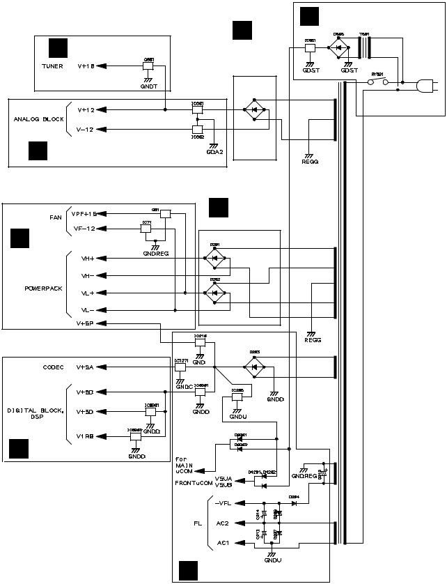
3.1.2 POWER SUPPLY BLOCKS
A
POWER LINE
N PRIMARY ASSY
D MOTHER ASSY |
B |
AUDIO |
|
|
INPUT |
|
ASSY |
|
D622-D625 |
B
P 12V ASSY
|
Q |
|
VHVL ASSY |
C |
I |
|
|
|
6CH AMP |
|
ASSY |
D |
|
F DSP ASSY
E
D MOTHER ASSY
F
|
|
|
|
|
|
|
16 |
|
VSX |
-C301 |
-S |
|
|
1 |
2 |
|
|
|
3 |
4 |
5 |
6 |
7 |
8 |
A
B
C
D
E
F
|
|
|
|
|
|
|
|
|
VSX |
-C301 |
-S |
7 |
17 |
5 |
6 |
|
|
|
8 |

1 |
2 |
3 |
4 |
3.2 OVERALL WIRING DIAGRAM
A
VIDEO ASSY |
C |
B (AWX8225) |
|
|
AUDIO INPUT ASSY |
|
(AWX8227) |
|
12V ASSY |
|
P (AWX8170) |
B
|
AC POWER CORD |
|
ADG7021 |
|
AC INLET ASSY |
|
VKP2126 |
|
N |
C |
PRIMARY ASSY |
|
(AWX8190) |
D
J4601
ADX7442
E G
FRONT IN ASSY (AWX8219)
M L
POWER SW ASSY
F (AWX8174)
|
|
|
|
|
|
18 |
|
VSX |
-C301 |
-S |
|
1 |
2 |
|
|
|
3 |
D D 1/5- D 5/5
MOTHER ASSY (AWX8197)
|
CN8003 |
F F 1/2- F 2/2 |
CN8009 |
|
|
DSP ASSY (AWX8241) |
|
CN8012 |
|
FRONT ASSY (AWX8199)
4

5 |
6 |
7 |
8 |
Note : When ordering service parts, be sure to refer to "EXPLODED VIEWS and PARTS LIST" or "PCB PARTS LIST".
A
FM/AM
TUNER
MODULE ASSY (AXQ7245)
E
DSP KAWA ASSY (AWX8167)
J AMP OUT ASSY (AWX8177)
O D5V ASSY (AWX8224)
H
AMP KAWA ASSY (AWX8223)
DC FAN MOTOR
AXM7025
I
6CH AMP ASSY (AWM7786)
Q
VHVL ASSY (AWX8259)
A
B
C
D
E
K
ENCODER ASSY (AWX8175)
F
|
|
|
|
|
|
|
|
|
VSX |
-C301 |
-S |
7 |
19 |
5 |
6 |
|
|
|
8 |

1 |
2 |
3 |
4 |
3.3 FM/AM TUNER MODULE
A
B
C
A FM/AM TUNER MODULE (AXQ7245)
FM FRONT END
(FM)
(FM) |
(FM) |
|
(FM)
(FM)
(FM)
D
(FM)
(AM)
E
F
A
20
1
(FM)
|
|
(FM) |
(FM) |
|
(AM) |
(AM) |
|
(AM) |
|
|
(AM) |
MW RF TUNING BLOCK |
|
|
(AM)
OSC : 981 - 2052kHz 9k step
VSX-C301-S
2 |
|
|
|
3 |
4 |
5 |
6 |
7 |
8 |
A
: The power supply is shown with the marked box.
(TX)
: AUDIO SIGNAL ROUTE (TUNER)
(AM)
: AM SIGNAL ROUTE
(FM)
: FM SIGNAL ROUTE
B
ATF7026 |
|
|
|
|
|
|
|
|
(AM) |
|
|
|
|
|
|
(AM) |
(AM)(AM) |
(AM) |
|
|
|
CN801 |
|
|
|
|
|
C |
|||
|
(AM) |
|
|
(TX) |
|
|
|
|
|
|
(FM) |
|
|
|
|
|
|
|
|
|
|
|
|
|
|
|
|
|
(TX) |
|
|
|
(FM) |
(AM) |
|
|
|
1/5 |
|
(AM) |
IF+MPX IC |
|
|
(TX) |
|
D |
|
|
AM/FM |
|
|
|
|
|
|
|
|
|
(TX) |
|
|
|
|
|
|
|
|
|
|
|
|
(FM) |
(FM) |
|
|
|
|
|
|
(AM) |
|
(TX) |
|
|
|
|
|
|
|
|
|
|
|
|
|
|
L201 |
|
|
|
|
D |
|
|
|
|
|
|
|
|
|
|
ATE7003 |
|
|
|
|
|
|
|
|
|
|
|
|
|
E |
PLL IC |
|
|
|
|
|
|
|
F
A
|
|
|
|
|
|
|
|
|
VSX |
-C301 |
-S |
7 |
21 |
5 |
6 |
|
|
|
8 |

1 |
2 |
3 |
4 |
3.4 VIDEO ASSY
A
 VIDEO BLOCK
B VIDEO ASSY (AWX8225)
B
C
D
REAR PANEL
E
F
B
IC2501 NJM2296M
D 1/5 CN9001
 : VIDEO SIGNAL ROUTE
: The power supply is shown with the marked box.
B
22 |
|
VSX-C301-S |
|
|
1 |
2 |
|
3 |
4 |

5 |
6 |
7 |
8 |
A
B
C
D
E
F
|
|
|
|
|
|
|
|
|
VSX-C301-S |
7 |
23 |
||
5 |
6 |
|
|
|
8 |
|

1 |
2 |
3 |
4 |
3.5 AUDIO INPUT ASSY
A |
|
(A) |
|
(A) |
(A) |
(A) |
|
B |
|
(A) |
|
(A) |
|
C |
|
C AUDIO INPUT ASSY (AWX8227)
D
(A)
(D) |
(D) |
E
(D) |
(D) |
(D) |
(A) |
F
C |
|
D 2/5 CN1263 |
|
24 |
|
VSX-C301-S |
|
1 |
2 |
3 |
4 |

5 |
6 |
(A)
(A) |
(A) |
(A) |
(A) |
P 601
CAUTION : FOR CONTINUED PROTECTION
AGAINST RISK OF FIRE.
REPLACE ONLY WITH SAME TYPE
NO. 49102.5 FOR IC820 AND IC821
MFD, BY LITTELFUSE INC.
5 |
6 |
7 |
8 |
D 2/5 CN1262
From
T1 PT
(A)
: AUDIO SIGNAL ROUTE (ANALOG)
(D)
:AUDIO SIGNAL ROUTE (DIGITAL)
:The power supply is shown with the marked box.
|
|
|
|
|
C |
|
|
|
|
|
|
|
|
|
-C301 |
|
|
|
|
|
VSX |
-S |
7 |
25 |
|||
|
|
|
8 |
|
|
|
A
B
C
D
E
F

1 |
2 |
3 |
4 |
3.6 MOTHER ASSY (1/5)
A
D 2/5 |
B
A CN201
C
B CN2501
D
D 2/5 

E
F
|
D |
1/5 |
: The power supply is shown with the marked box. |
|
|
N |
CN551 |
||||
|
|
|
|||||||||
|
|
|
|||||||||
|
|
|
|
|
|
|
|
||||
|
|
|
|
|
|
|
|
||||
26 |
|
|
|
|
|
|
|
|
|
|
|
|
|
|
|
|
|
|
|
|
|
||
|
|
VSX |
-C301 |
-S |
|
|
|
|
|
||
1 |
2 |
|
|
|
3 |
4 |
|||||

5 |
6 |
7 |
L CN4203
D 1/5 MOTHER ASSY (AWX8197)
DC DETECT: 3-4V OVERLOAD DETECT: 2-3V Short-circuit Fan and Power supply circuit: less than 2V (VH/VL)
F 2/2 CN8012
VSX-C301-S
5 |
6 |
|
|
|
7 |
8
A
B
C
D 3/5
D
D 2/5
E
D 2/5
F
D 1/5
27
8

|
1 |
|
|
|
|
|
|
|
2 |
|
|
|
3 |
|
|
3.7 MOTHER ASSY (2/5) and DSP KAWA ASSY |
|
||||||||||||
|
|
|
|
|
|
|
|
4/5 |
|
|
1/5 |
|
||
|
|
|
|
|
|
|
D |
|
||||||
A |
|
|
|
|
|
|
|
D |
|
|||||
|
|
|
|
|
|
|
|
|||||||
|
|
|
|
|
|
|
|
|
|
|
|
|
|
|
|
|
|
|
|
|
|
|
|
|
|
|
|
|
|
|
|
|
|
|
|
|
|
|
|
|
|
|
|
|
|
|
|
|
|
|
|
|
|
|
|
|
|
|
|
B
C
G CN4102
C CN701
(A) |
(A)
(A)
(A)
INPUT ATT
D
CN901 |
(D) |
|
|
C |
(A) |
E
(A) |
(A) |
|
(D)
F
F 1/2 |
CN8017 |
F 1/2 |
D 2/5 E |
|
|
|
CN8003 |
|
28 |
|
VSX-C301-S |
1 |
2 |
3 |
4
D 1/5
NORMAL : 0V
OVERLOAD : 5V
(A)
(A)
(A)
IATT
ON : +12V
OFF : -12V
A/D OVERLOAD
DETECT
 (A)
(A)
(A)
(A) |
(A) |
E
|
|
DSP KAWA ASSY |
(A) |
(A) |
(AWX8167) |
|
(A)
(A)
F 1/2 CN8009 
4

5 |
6 |
D 2/5 MOTHER ASSY (AWX8197)
LOW PASS FILTER
(A)
(A) |
(A) |
(A)
7 |
8 |
(A) |
A |
: AUDIO SIGNAL ROUTE (ANALOG)
(D)
: AUDIO SIGNAL ROUTE (DIGITAL)
B
C
(A)
D 3/5
(A)
D
For SP CONFIG. MIX AMP
(A)
E
F
: The power supply is shown with the marked box.
D 2/5
|
|
|
|
|
|
|
|
|
VSX |
-C301 |
-S |
7 |
29 |
5 |
6 |
|
|
|
8 |

1 |
|
2 |
3 |
|
|
4 |
|
|
|
|||
3.8 MOTHER ASSY (3/5) |
|
|
|
|
|
|
|
|
||||
|
|
|
|
|
|
|
|
|
|
1/5 |
||
A |
|
|
|
|
|
D |
||||||
D |
3/5 MOTHER ASSY (AWX8197) |
|
|
|
||||||||
|
|
|
|
|
|
|
|
|
|
|
||
|
|
|
|
|
|
|
|
|
|
|
||
|
|
|
|
|
|
|
|
|
|
|
|
|
|
|
|
|
|
|
|
|
|
|
|
|
|
|
|
|
|
|
|
|
|
|
|
|
|
|
|
|
|
|
|
|
|
|
|
|
|
|
|
|
|
|
|
|
|
|
|
|
|
|
|
|
|
|
|
|
|
|
|
|
|
|
|
|
|
|
|
|
|
|
|
|
|
|
|
|
|
|
|
|
|
|
|
|
|
|
|
|
|
|
|
|
|
|
|
|
|
|
|
|
|
|
|
|
B
D 2/5
(A)
(A) |
(A) |
(A) |
|
|
C
D
E
F
D 3/5
|
|
|
|
|
|
|
30 |
|
VSX |
-C301 |
-S |
|
|
1 |
2 |
|
|
|
3 |
4 |
Loading...