


> Before start > Hookup > Setup > Playback > Part Names
Basic
Manual
VSX-LX301
AV Receiver
Hookup |
|
Step1: Choose your Speaker Layout |
...................................... 3 |
Step2: Connect the Speakers ................................................. |
9 |
Step3: Connect the TV ......................................................... |
12 |
Step4: Connect the AV Components .................................... |
14 |
Step5: Connect Other Cables ............................................... |
18 |
Setup |
|
Step6: Power On & Initial Setup ........................................... |
19 |
HDMI Setup .......................................................................... |
20 |
Playback |
|
Basic Playback ..................................................................... |
21 |
Network Functions ................................................................ |
22 |
Others ................................................................................... |
24 |
Part Names |
|
Front Panel ........................................................................... |
26 |
Rear Panel ............................................................................ |
27 |
Remote Controller ................................................................ |
28 |
Display .................................................................................. |
28 |
This manual includes information needed when starting up and also instructions for frequently used operations. The "Advanced Manual" is available on the internet with details about the playback features/ listening modes/settings details, specifications, and troubleshooting. The Advanced Manual is created in a format that makes it easy to read on a PC or Smartphone.
http://www.pioneer-audiovisual.com/manual/vsxlx301/adv/en.html
En
Fr
Es
Advanced Manual found here
> Before start > Hookup > Setup > Playback > Part Names
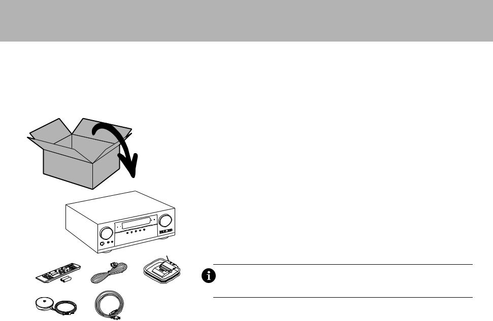
What's in the box
1. |
Main unit 2. Remote controller (RC-914R) ×1, Batteries (AAA/R03) ×2 |
3. |
Indoor FM antenna ×1 4. AM loop antenna ×1 5. Speaker setup microphone ×1 |
6. |
Power cord ×1 |
Main features
This unit is connected between your TV and your AV components. To play, select the source with the input selector. You can connect 7.1ch of speakers to this unit, with 7ch at 170 W (6 ohms, 1 kHz, 0.9%THD) per channel plus a powered subwoofer pre out jack.
$ Supports playback in Dolby Atmos format which provides 360e sound placement
$ The HDMI jack supports 4K video input and output. Jacks IN1 to 3 and OUT MAIN/SUB support HDCP2.2
$HDMI CEC functionality: Control features such as linking input switching with the input selector and players conforming to the CEC standard, switching audio output and volume using the remote controller of a CEC-
|
|
compliant TV, and automatically switching this unit to standby when the TV is turned off |
|
|
$ HDMI Standby Through: Video and audio signals from AV components can be transmitted to the TV even if this |
|
|
unit is in standby |
|
|
$ ARC: Connection with an ARC-compatible TV is complete with one HDMI cable |
|
|
$ Easy Initial Setup using onscreen guidance and On-Screen Display (OSD) showing operations on the TV |
1 |
|
$ Internet radio and AirPlay via wired LAN or Wi-Fi (wireless LAN) and network features such as Music Server |
|
that enables PC music file playback, USB playback, plus other playback features such as AM/FM radio and |
|
|
|
BLUETOOTH® play |
|
|
$ Playback formats supported by Music Server and USB include WAV, FLAC and DSD high-res source |
|
|
$ Multi-zone Connection which allows you to play in the main room and listen in a separate room (ZONE 2) |
|
|
$ You can connect a speaker B system |
|
|
$ Equipped with RS-232C port, IR IN/OUT jack, and 12V TRIGGER OUT A/B jacks |
|
|
$ We plan to provide support for the DTS:X audio format through a firmware update for this unit. Refer to our |
2 |
3 |
homepage for more information. |
4 |
||
|
|
CAUTION: Connect speakers with 6 Ω to 16 Ω impedance. The power cord must be connected only after |
|
|
all other cable connections are completed. |
|
|
0 We will not accept responsibility for damage arising from the connection of equipment manufactured by |
5 |
6 |
other companies. |
|
2
> Before start > Hookup > Setup > Playback > Part Names
Step1: Choose your Speaker Layout
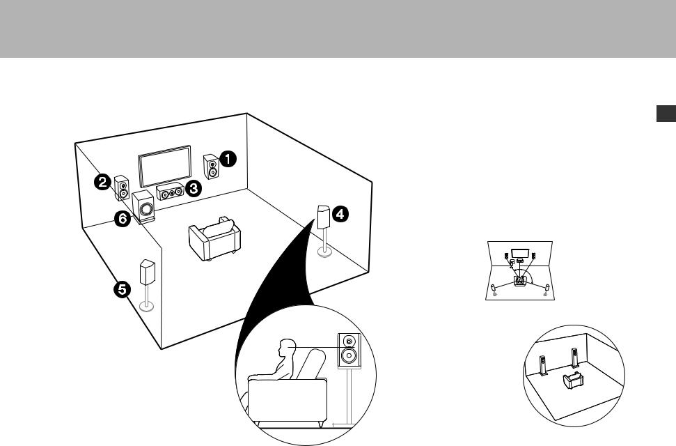
12 Front Speakers
3 Center Speaker
45 Surround Speakers
6Powered Subwoofer
 For 5.1-Channel System
En
This is a 5.1-channel system that is the basic surround system.
Front speakers output front stereo sound and a center speaker outputs center sound such as dialogs and vocals. Surround speakers create back sound field. Powered subwoofer reproduces bass sounds and creates rich sound field. The front speakers should be positioned at ear height, while the surround speakers should be positioned just above ear height. Center speaker should be set up facing the listening position. Place the powered subwoofer towards the front. Placing it between the center speaker and a front speaker gives you a natural sound even when playing music.
0The front speakers, center speaker, and surround speakers are counted as 5 channels, and the powered subwoofer is counted as 0.1 of a channel, giving us the name 5.1ch system.
Go To "Hookup" ( P9)
1
2
1: 22e to 30e, 2: 120e
 Speaker B System
In a 5.1-Channel System, you can connect one more set of front speakers to use as a Speaker B System. In this state, the 5.1- Channel System becomes the Speaker A System and you can switch the same audio to output from A, B, or A+B. Note that sound is not output from Speaker B when Zone
Speaker is used ( |
P17). |
Go To "Hookup" ( |
P9) |
3
> Before start > Hookup > Setup > Playback > Part Names
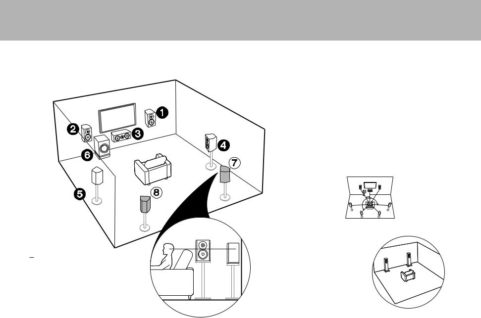
1 6 ( P3)
78 Surround Back Speakers
 For 7.1-Channel System (with
Surround Back Speakers)
This is a system with surround back speakers added to the basic 5.1-channel system. The connection of surround back speakers improves the sense of envelopment and connectivity of sound created by the back sound field and provides a more real sound field. You can select the Dolby Atmos listening mode, which realizes the most up-to-date 3D surround sound, when the input format is Dolby Atmos. With formats other than Dolby Atmos, you can still create a sound field by outputting sound from the surround back speakers when you select the Dolby Surround listening mode. The optimal positioning is for surround back speakers to be at ear height. Place the surround speakers in a more slightly forward position than you would in a 5.1-channel system. 0 If you are including surround back speakers in the setup, surround
speakers are required.
Go To "Hookup" ( P9)
1
2
3
1: 22e to 30e, 2: 90e to 110e, 3: 135e to 150e
 Speaker B System
In a 7.1-Channel System (with Surround Back Speakers), you can connect one more set of front speakers to use as a Speaker B System. In this state, the 7.1-Channel System becomes the Speaker A System and you can switch the same audio to output from A, B, or A+B. Note that sound is not output from the surround back speaker when A+B is selected. Note that sound is not output from Speaker B when Zone Speaker is used ( P17).
Go To "Hookup" ( P9)
4
> Before start > Hookup > Setup > Playback > Part Names
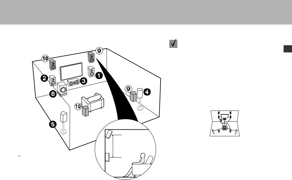
3´ (0.9 m) or more
1 6 ( P3)
9: Height Speakers
Choose one of the following:
$ Front High Speakers
$ Rear High Speakers
For 7.1-Channel System |
|
(with Height Speaker-A) |
En |
This is a basic 5.1-channel system with the addition of height speakers, either as front high speakers or rear high speakers. Select which speakers to setup according to the environment of the room. You can select the Dolby Atmos listening mode (5.1.2 channel playback), which realizes the most up-to-date 3D surround sound including overhead sounds, when the input format is Dolby Atmos. With formats other than Dolby Atmos, you can still create a sound field by outputting sound from the height speakers when you select the Dolby Surround listening mode. Front high speakers or rear high speakers should be situated at least 0.9 m higher than the front speakers. Front high speakers should be situated directly above the front speakers and the distance between the rear high speakers should match the distance between the front speakers. Both should be set up facing the listening position.
Go To "Hookup" ( P10)
1
2
1: 22e to 30e, 2: 120e
5
> Before start > Hookup > Setup > Playback > Part Names
 For 7.1-Channel System
(with Height Speaker-B)
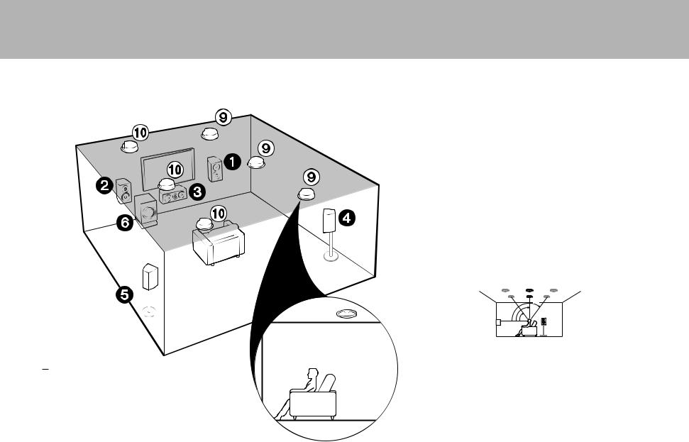
This is a basic 5.1-channel system using ceiling speakers, for example, with the addition of height speakers, either as top front speakers, top middle speakers, or top rear speakers. Select which speakers to setup according to the environment of the room. You can select the Dolby Atmos listening mode (5.1.2 channel playback), which realizes the most up-to-date 3D surround sound including overhead sounds, when the input format is Dolby Atmos. With formats other than Dolby Atmos, you can still create a sound field by outputting sound from the height speakers when you select the Dolby Surround listening mode. Fit top front speakers on the ceiling forward of the seating position, top middle speakers on the ceiling directly above the seating position, and top rear speakers on the ceiling behind the seating position. The distance between each pair should match the distance between the two front speakers.
0 Dolby Laboratories recommends placing this type of height speakers to obtain the best Dolby Atmos effect.
Go To "Hookup" ( P10)
3
2


 1
1
1: 30e to 55e, 2: 65e to 100e, 3: 125e to 150e
1 6 ( P3)
9: Height Speakers
Choose one of the following:
$ Top Front Speakers
$ Top Middle Speakers
$ Top Rear Speakers
6

> Before start > Hookup > Setup > Playback > Part Names
 For 7.1-Channel System
(with Height Speakers-C)
En
This is a basic 5.1-channel system that using Dolby enabled speakers, with the addition of height speakers, either as Dolby enabled speakers (front) or Dolby enabled speakers (surround) or Dolby enabled speakers (surround back). Select which speakers to setup according to the environment of the room. Dolby enabled speakers are special speakers designed to face the ceiling so that sound is heard after bouncing off the ceiling so that sound appears to be coming from overhead. You can select the Dolby Atmos listening mode (5.1.2 channel playback), which realizes the most up-to-date 3D surround sound including overhead sounds, when the input format is Dolby Atmos. With formats other than Dolby Atmos, you can still create a sound field by outputting sound from the height speakers when you select the Dolby Surround listening mode. Place them either above the front speakers or above the surround speakers or surround back speakers. If they are integrated Dolby enabled speakers, put in place of the front speakers, the surround speakers, or the surround back speakers.
Go To "Hookup" ( P10)
1
2
3
1: 22e to 30e, 2: 90e to 120e, 3: 135e to 150e
1 6 ( P3)
9: Height Speakers
Choose one of the following:
$ Dolby Enabled Speakers (Front)
$ Dolby Enabled Speakers (Surround)
$ Dolby Enabled Speakers (Surround Back)
7
> Before start > Hookup > Setup > Playback > Part Names
 For Bi-Amping the Speakers
It is possible to connect front speakers supporting Bi-Amping to improve quality of the bass and treble. The maximum number of channels available with this connection is 5.1 because Bi-Amping speakers require one amplifier for the tweeter jacks and one amplifier for the woofer jacks. The effects and placements for speakers are the same as the 5.1-channel plan that doesn't use Bi-Amping speakers.
Go To "Hookup" ( P11)
1
2
1: 22e to 30e, 2: 120e
12 Front Speakers (Bi-Amping)
3 Center Speaker
45 Surround Speakers
6Powered Subwoofer
8

> Before start > Hookup > Setup > Playback > Part Names
Step2: Connect the Speakers
1/2˝ (12 mm)
1
in case of: |
|
Pages 3 to 4 |
En |
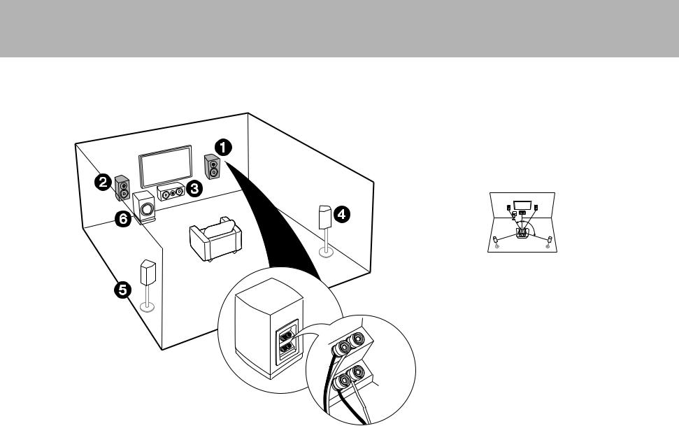
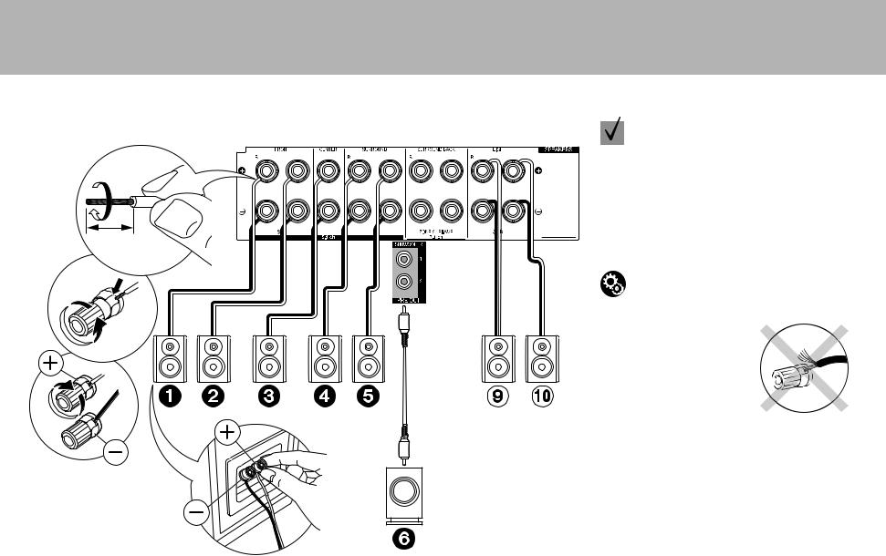
Connect 123456 for a 5.1-channel system. With a 7.1-Channel System (with Surround Back Speakers), also connect 7 and 8. Up to two powered subwoofers can be connected. The same signal is output from each of the SUBWOOFER jacks. With this connection, you can connect one more set of front speakers to use as a Speaker B System. Switch Speakers A/B with AV Adjust ( P25). Note that sound is not output from the surround back speaker when A+B is selected.
Setup
0 Settings for the speaker configuration you have connected need to be made in "1. Full Auto MCACC" ( P19) in Initial Setup.
2 
1 Speaker cable, 2 Subwoofer cable
Speaker B
Make sure the exposed wires of the speakers do not stick out of the speaker terminals when connecting. If the exposed wires of the speakers touch the rear panel or the + and – wires touch each other, the protection circuit will be activated.
9
> Before start > Hookup > Setup > Playback > Part Names
1/2˝ (12 mm)
|
in case of: |
|
Pages 5 to 7 |
|
Connect 1234569:. Up to two powered |
|
subwoofers can be connected. The same signal is output |
|
from each of the SUBWOOFER jacks. |
|
0 Apart from these connections, you can also connect |
|
surround back speakers and . However, you can |
|
only output audio from one set of or at a time. |
|
When both are connected, you can select which |
|
speakers to prioritize with AV Adjust ( P25). |
1 |
Setup |
0 Settings for the speaker configuration you have |
connected need to be made in "1. Full Auto MCACC" ( P19) in Initial Setup.
Make sure the exposed wires of the speakers do not stick out of the speaker terminals when connecting. If the exposed wires of 2 the speakers touch the rear panel or the + and – wires touch each
other, the protection circuit will be activated.
1 Speaker cable, 2 Subwoofer cable
10
> Before start > Hookup > Setup > Playback > Part Names
1/2˝ (12 mm)
in case of: |
|
Page 8 |
En |
Connect front speakers compatible with Bi-Amping connection to the FRONT jacks and the SURROUND BACK jacks. Make sure you remove the jumper bar fitted between the woofer jacks and tweeter jacks of the front speakers. In case of Bi-Amping connection, refer to the instruction manual of your speakers. Up to two powered subwoofers can be connected. The same signal is output from each of the SUBWOOFER jacks.
|
Setup |
|
0 Bi-Amping connection requires you to change |
1 |
some settings. Select "Yes" in "Bi-Amp" in "1. Full |
Auto MCACC" ( P19) in the Initial Setup. |
For high- |
2 |
Make sure the exposed wires of the speakers do not stick out of |
frequency |
the speaker terminals when connecting. If the exposed wires of |
|
For low- |
|
the speakers touch the rear panel or the + and – wires touch each |
|
other, the protection circuit will be activated. |
|
frequency |
|
|
1 Speaker cable, 2 Subwoofer cable
11
> Before start > Hookup > Setup > Playback > Part Names
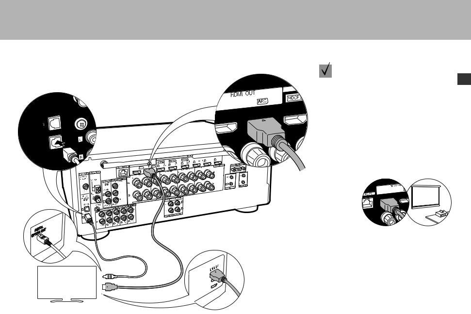
Step3: Connect the TV
 if you have:
ARC TV
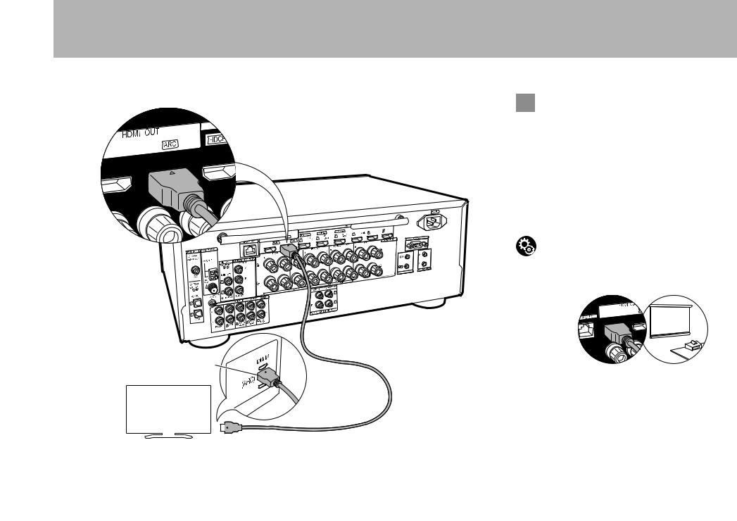
This unit is connected between your TV and AV components. If you connect two or more AV components, you can select the video displayed on the TV and the audio output from this unit by changing the input selector. Shown here are the connections for a TV that supports the ARC (Audio Return Channel) feature. By connecting with a single HDMI cable, you can not only output the video input to this unit to the TV, but you can also play the sound from the TV through this unit.
Choose an HDMI IN jack on the TV that supports ARC when connecting.
Setup
0 Settings are required to use the ARC function. Select "Yes" in "5. Audio Return Channel" ( P20) in the Initial Setup.
0 Please refer to the TV's operation manual for directions on connections and setup for the TV.
1
HDMI IN (ARC)
Another TV or projector can be connected to the HDMI OUT SUB jack. This jack does not support ARC. For details about how to output the video to a connected device ( P21)
TV
1 HDMI cable
12
> Before start > Hookup > Setup > Playback > Part Names
if you have: |
|
Non-ARC TV |
En |
This unit is connected between your TV and AV components. If you connect two or more AV components, you can select the video displayed on the TV and the audio output from this unit by changing the input selector. This describes the connections for a TV that does not support the ARC (Audio Return Channel) feature. By connecting with both an HDMI cable and a digital optical cable, you can not only output the video input to this unit to the TV, but you can also play the sound from the TV through this unit.
0 Connection with a digital optical cable is not necessary if you will watch TV through a device such as a cable set-top box (that is, not use a tuner built into the TV).
Another TV or projector can be connected to the HDMI OUT SUB jack. This jack does not support ARC. For details about how to output the video to a connected device ( P21)
TV
1 HDMI cable, 2 Digital optical cable
13
> Before start > Hookup > Setup > Playback > Part Names
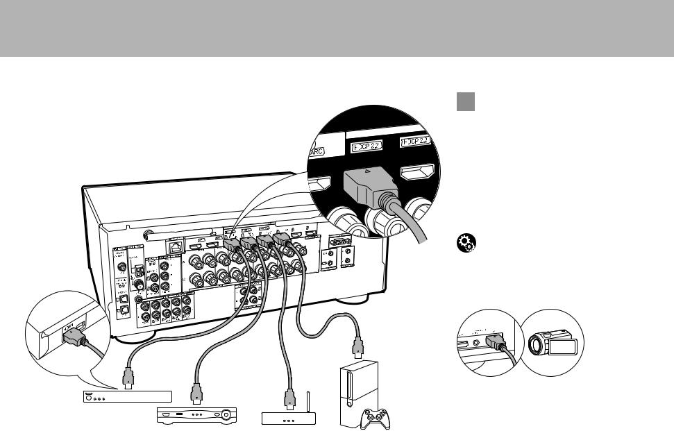
Step4: Connect the AV Components
 if you have:
HDMI AV Components
This is an example of connection with an AV component that has an HDMI jack. With connection to an AV component that conforms with the CEC (Consumer Electronics Control) standard, you can use features such as the HDMI CEC feature that links with the input selector, and the HDMI Standby Through feature which allows you to play video and audio from AV components on the TV even when this unit is in standby mode.
0 To play 4K or 1080p video, use a high speed HDMI cable. Further, to enjoy HDCP2.2 compatible video, connect to the HDMI IN1 to IN3 jacks.
Setup
0 HDMI setup ( P20) is required to use the HDMI CEC and HDMI Standby Through features. Make settings after all connections are complete.
0 To enjoy digital surround sound including Dolby Digital, audio output should be set to "Bitstream output" on the connected Blu-ray Disc player or other device.
1
You can connect a device such as a video camera to the AUX
INPUT HDMI jack on the front panel.
BD/DVD
Cable/Satellite set-top |
Streaming media |
GAME |
|
box |
player |
||
|
1 HDMI cable
14
> Before start > Hookup > Setup > Playback
1
2 OR 3
> Part Names
 if you have:
Non-HDMI AV Components En
This is an example of connection with an AV component that does not have an HDMI jack. Make the connections to the AV component to match the jacks it has. When video input connection is to the BD/DVD jack, the audio input connection should also be to the BD/DVD jacks, and so on, so that you connect the video input jacks to the jacks with the same name as the audio input jacks. Note that video signals input to the VIDEO IN jack or the COMPONENT VIDEO IN jacks will be upconverted to HDMI signals and then output from the HDMI OUT jack.
0To enjoy digital surround playback in formats such as Dolby Digital, you need to make a connection for audio signals with a digital coaxial cable or digital optical cable.
Setup
0The COMPONENT VIDEO IN jacks are compatible only with 480i or 576i resolution. When you input video signals to the COMPONENT VIDEO IN jacks, set the output resolution of the player to 480i or 576i. Select interlace if there is no option for 480i, etc. If your player does not support 480i or 576i output, use the VIDEO IN jack.
0To enjoy digital surround sound including Dolby Digital, audio output should be set to "Bitstream output" on the connected Blu-ray Disc Player or other device.
BD/DVD
1 Component video cable, 2 Digital optical cable, 3 Analog audio cable
15
> Before start > Hookup > Setup > Playback > Part Names
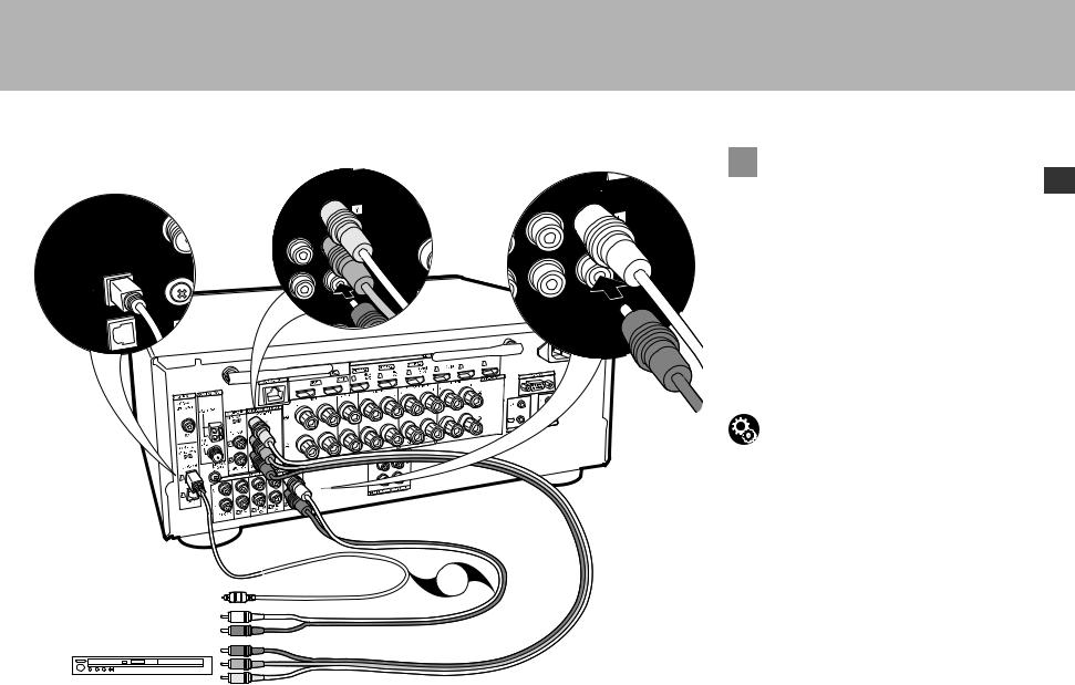
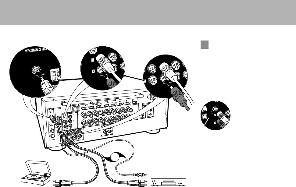
 if you have:
Audio Components
Example of a connection with an audio component. Connect a CD player using a digital coaxial cable or analog audio cable. You can also connect a turntable that has an MM-type cartridge to the PHONO jack.
0 If the turntable has a built-in audio equalizer, connect it to another AUDIO IN jack. Further, if the turntable uses an MC type cartridge, install an audio equalizer compatible with the MC type cartridge between the unit and the turntable, then connect to any AUDIO IN jack other than the PHONO jack.
If the turntable has a ground wire, connect it to the SIGNAL GND terminal of this unit.
OR 1
2
Turntable |
CD |
1 Digital coaxial cable, 2 Analog audio cable
16
> Before start > Hookup > Setup > Playback > Part Names
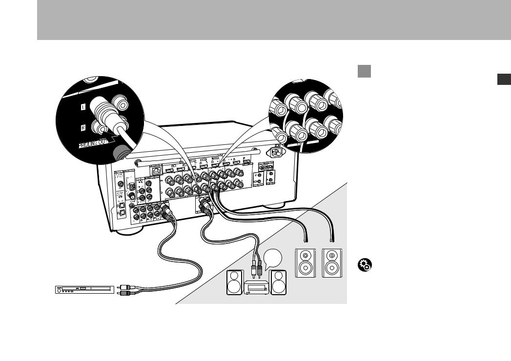
 Multi-zone Connection
En
You can enjoy audio in the separate room by, for example, playing a Blu-ray Disc player in the main room (where this unit is located) and listening to internet radio in the separate room (ZONE 2).
0 DSD and Dolby TrueHD audio signals are not output to ZONE 2 when selected with the "NET" input selector.
Connections with an AV component
When outputting the audio of an external AV component to ZONE 2, you need to connect using an analog audio cable.
ZONE 2 PRE/LINE OUT
It is possible to play 2 ch source in a separate room while 7.1 ch source is being played in the main room. Connect
the ZONE 2 PRE/LINE OUT jacks of the unit and the MAIN ROOM LINE IN jacks of the pre-main amplifier or the powered
amplifier in a separate room with an analog audio cable.
2
1
LINE
IN
ZONE2
ZONE SPEAKER
ZONE SPEAKER
It is possible to connect speakers in a separate room and play 2 ch sources.
0You can play through a maximum of 5.1 channels in the main room during ZONE 2 playback. Listening modes such as the Dolby Atmos modes cannot be selected.
0Note that sound is not output from Speaker B when Zone Speaker is used.
Setup
0 Settings are required in Initial Setup, "4. Multi Zone Setup" ( P20) to enjoy this feature.
BD/DVD |
ZONE2 PRE/LINE OUT |
1 Analog audio cable, 2 Speaker cable
17
> Before start > Hookup > Setup > Playback
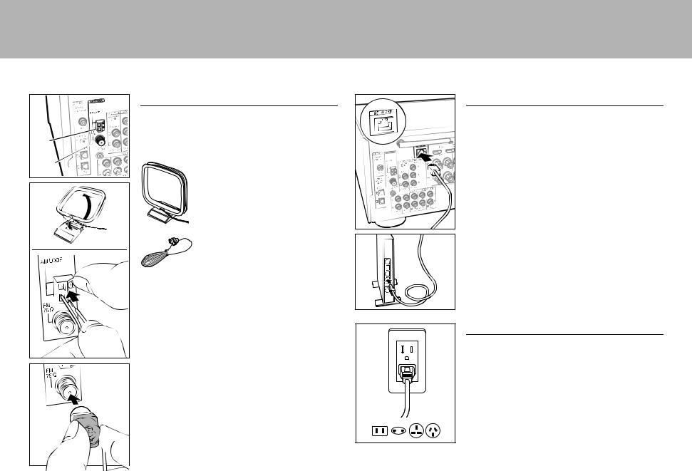
Step5: Connect Other Cables
Antenna Hookup
Move the antenna around while playing the radio to find
the position with the best reception. Use a thumb tack or
similar to attach the indoor FM antenna to a wall.
AM
FM
AM loop antenna
 Indoor FM antenna
> Part Names
Network Hookup
Connect this unit to the network using wired LAN or Wi-Fi (wireless LAN). You can enjoy network features such as internet radio, Music Server, and AirPlay by connecting the unit to the network.
If you connect by wired LAN, connect with an Ethernet cable to the NETWORK port as shown in the illustration. To connect by Wi-Fi, then after selecting "Wireless" in "3. Network Connection" ( P20) in Initial Setup, select the desired setting method and follow the onscreen instructions to configure the connection.
Power Cord Hookup
This unit includes removable power cords. Connect the power cord to the power outlet after completing all other connections. Connect the power cord to AC IN of the unit and then connect to the outlet. Always disconnect the outlet side first when disconnecting the power cord.
18
> Before start > Hookup > Setup > Playback > Part Names
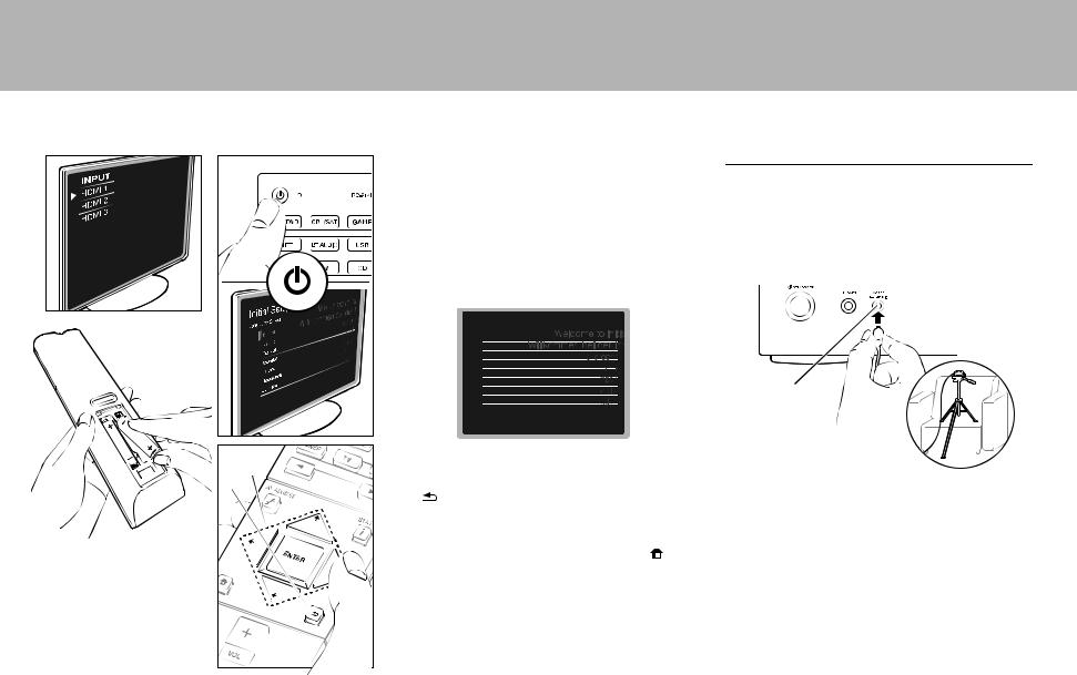
Step6: Power On & Initial Setup
Initial Setup starts automatically
Once all connections are complete, change the TV's input to the input for this unit, inset batteries in the remote controller, and press Í to turn the power on. When you turn the unit on for the first time, Initial Setup is automatically shown on the TV to enable you to make settings required for startup using simple operations following onscreen guidance.
These instructions will guide you through some items that you need to check beforehand. Read beforehand so the setup goes smoothly.
Initial Setup
Language Select
 English
Deutsch
Français
Español
Italiano
Nederlands
Svenska
a |
Operation |
|
Select the item with the cursors of the remote controller |
||
b |
and press ENTER (a). To return to the previous screen, |
|
|
press |
(b). |
To redo the Initial Setup |
|
If you terminate the procedure on the way or want to |
|
change a setting made during Initial Setup, press |
on |
the remote controller, select "System Setup" – |
|
"Miscellaneous" – "Initial Setup" from Home, and press ENTER.
1. Full Auto MCACC
Place the supplied speaker setup microphone in the |
En |
|||||
listening position, measure the test tones emitted by the |
|
|||||
|
||||||
speakers, then the unit automatically sets the optimum |
|
|||||
volume level for each speaker, the crossover frequencies, |
|
|||||
and the distance from the listening position. This also |
|
|||||
enables correction of distortion caused by the acoustic |
|
|||||
environment of the room. |
|
|||||
|
|
|
|
|
|
|
|
|
|
|
|
|
|
|
|
|
|
|
|
|
MCACC
SETUP MIC
0 Use a tripod or similar to place the speaker setup microphone at ear height.
0 The subwoofer sound may not be detected since it is extremely low frequencies. Set the subwoofer volume to more than halfway.
0 Calibration takes several minutes to be completed. The speakers emit the test tone at high volume during measurement, so be careful of your surroundings. Keep the room as quiet as possible during measurement. If the measurement is interrupted, turn off the household appliances.
19
> Before start > Hookup > Setup > Playback > Part Names
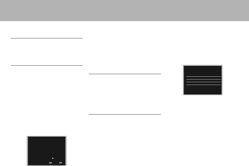
2. Source Connection
Check that each input source is connected correctly. Follow the guidance, select the input you want to confirm, start play of the selected player, and confirm that the images appear on the TV and that sound is played.
3. Network Connection
Set up Wi-Fi connection with an access point such as a wireless LAN router. There are the following two methods of connecting by Wi-Fi:
"Scan Networks": Search for an access point from this unit. Find out the SSID of the access point beforehand.
"Use iOS Device (iOS7 or later)": Share the iOS device's Wi-Fi settings with this unit.
If you select "Scan Networks", there are a further two choices of connection method. Check the following.
0 "Enter Password": Enter the password (or key) of the access point to connect.
0 "Push Button": If the access point has an automatic connection button, you can connect without entering a password.
0 If the SSID of the access point is not displayed, then in the screen listing the SSIDs, select "Other..." with the cursor on the remote controller and press ENTER, then follow the onscreen instructions.
Keyboard input
Wi-Fi Setup
SSID
|
|
|
|
|
|
|
a b c d e |
f |
g h |
i j k l |
m |
||
|
|
|
||||
n o p q r s t u v w x y |
z |
|||||
1 2 3 4 5 |
6 7 8 9 0 - ^ |
\ |
|
|||
, . / ; : |
@ |
[ ] |
̺ |
|
|
|
|
A/a |
* |
* |
OK |
|
|
When finished, select the "OK" key. |
|
|
|
|||
|
|
|
|
All Erase |
A/a |
|
To switch between upper and lower case, select "A/a" on the screen and press ENTER. To select whether to mask the password with " " or display it in plain text, press +Fav on the remote controller. Press CLEAR to delete all the input characters.
0A confirmation screen asking you to agree to the privacy policy is displayed during network setting. Select "Yes" and press ENTER to indicate agreement.
4. Multi Zone Setup
When you want to enjoy audio in a room other than the main room, set the audio output method for the separate room (ZONE2). If you have connected speakers in a separate room with speaker cable, select "Using AV Receiver". If you have connected a pre-main amplifier in a separate room with an analog audio cable, select "with External Premain Amplifier". If you have connected a power amplifier, select "with External Power Amplifier".
5. Audio Return Channel
If you have connected a TV that supports ARC, select "Yes". This unit's ARC setting turns on and you can listen to the TV's audio through this unit.
HDMI Setup
HDMI CEC
Make this setting to enable the control feature for devices complying with the CEC standard. This is set to on automatically if you have selected "Yes" in "5. Audio Return Channel" in the Initial Setup.
Press the button on the remote controller to set "System Setup" – "Hardware" – "HDMI" – "HDMI CEC" to "On" on the TV screen. Also enable the CEC control feature on the CEC device you have connected.
HDMI
HDMI CEC |
On |
HDMI Standby Through |
Auto(Eco) |
Audio TV Out |
Auto |
Audio Return Channel |
Auto |
Auto Delay |
On |
HDMI Standby Through
Even if this unit is in standby, the input signals from AV components are transmitted to the TV.
0"Auto" / "Auto (Eco)": Select one of these settings when connected AV components comply with the CEC standard. Irrespective of the input selector selected immediately before switching the unit to standby, you can transmit the input signals from AV components to the TV. Select "Auto (Eco)" if the TV is also CEC-compliant. You can reduce power consumption in standby mode.
0"Input selector names for BD/DVD, etc.": You can transmit the input signals from the set input selector to the TV. It can be selected when "HDMI CEC" is set to "Off".
0"Last": You can transfer the input signals of the input selector selected immediately prior to the unit being switched to standby. It can be selected when "HDMI CEC" is set to "Off".
To exit the settings, press  .
.
20
> Before start > Hookup > Setup > Playback > Part Names
Basic Playback
AV Component Playback
a |
1. Switch the input on the TV to that assigned to |
||
|
|||
|
the unit. |
|
|
|
2. Press the input selector (a) on the remote |
||
|
controller with the same name as the jack to |
||
|
which you connected the player to switch the |
||
|
input. |
|
|
|
For example, press BD/DVD to play the |
||
|
player connected to the BD/DVD jack. Press |
||
|
TV to listen the TV's sound. |
||
|
You can also select input with the 21 |
||
|
buttons. |
|
|
|
0 When the CEC link function works, the |
||
|
input switches automatically when you |
||
|
have connected a CEC compliant TV and |
||
|
player to this unit using HDMI connection. |
||
e |
3. Start play on the player. |
||
d |
4. Use VOL+/– (b) to adjust the volume. |
||
When a TV is connected to the HDMI OUT |
|||
c |
|||
|
SUB jack |
|
|
|
Press the |
button on the remote controller to |
|
|
display the AV Adjust, and set "Other" – "HDMI |
||
|
Out" to either "SUB" or "MAIN+SUB". |
||
Listening Mode
This unit is equipped with a variety of listening modes. For details on the listening modes, see the Advanced Manual. This section introduces some of the popular modes.
0A future firmware update is planned to enable this unit to support playback in DTS Neural:X audio format. Neo:6 Cinema and Neo:6 Music are available until an update.
AUTO/DIRECT button (c)
You can select the Auto Surround, Direct, and
Pure Direct modes. In either case, for 2 channel input signals the Stereo mode is automatically selected that plays only from the front speakers and subwoofer, and for multi-channel input signals listening modes are automatically selected that match the input signal, so Dolby Digital for Dolby Digital sources, and DTS-HD Master Audio for DTS-HD Master Audio. The Direct mode shuts down some processing that can affect sound quality, such as the tone control features, so you can enjoy even better sound quality. The Pure Direct mode shuts down even more processes that affects sound quality, so you get a more faithful reproduction of the original sound. In this case, the speaker calibration made with MCACC is disabled.
0Depending on the input signal and speaker configuration, the Dolby Surround and DTS Neural:X modes that expand 2 channel and
5.1channel input signals to 5.1 channel and
7.1channel may be automatically selected.
SURR button (d)
You can select a variety of listening modes to suit your taste. There are the Dolby Digital, DTS-HD Master Audio, and Stereo modes that you can choose to suit the input signal, or the Dolby Surround and DTS Neural:X modes that can expand 2 channel and 5.1 channel input signals to 5.1 or 7.1 channels. You can also enjoy original surround modes such as Ext.Stereo and Drama modes.
STEREO button (e)
You can select the "Stereo" mode to playback only from the front speakers and subwoofer.
The listening mode last selected for the source is remembered for each of the AUTO/DIRECT, SURR, and STEREO buttons. If content you play is not supported by the listening mode you
selected last, the listening mode that is standard for that content is selected automatically.
Press  (f) repeatedly to switch the display of En the main unit in order of:
21
> Before start > Hookup > Setup > Playback > Part Names
Network Functions
Network Services
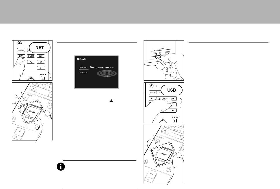
1. Switch the input on the TV to that assigned to the unit. 2. Press NET to display the network service list screen.
a
b |
3. Select the item with the cursors of the remote controller |
||||
|
and press ENTER to confirm your selection (a). To |
||||
|
return to the previous screen, press |
(b). |
|
|
|
|
|
||||
|
Internet Radio |
|
|
|
|
|
When this unit is connected to a network, you can listen to |
||||
|
TuneIn or other preregistered Internet radio services. After |
|
|
|
|
|
|
|
|
||
|
selecting the desired service, follow the on-screen |
||||
|
instructions, using the cursors to select radio stations and |
||||
|
programs, then press ENTER to play. Play starts when |
||||
|
100% is displayed for buffering. |
|
a |
||
Music Server
You can play music files stored on home-network compliant PCs or NAS devices connected to the same network as this unit. Select the server with the cursors, select the desired music file and press ENTER to start playback. Play starts when 100% is displayed for buffering.
Notes:
0 Network services become selectable after the network starts up even if they cannot be selected first.
0 Functionality may be introduced by firmware updates and service providers may cease services, meaning that some network services and content may become unavailable in the future. Furthermore, available services may vary depending on your area of residence.
USB
Play music files on a USB storage device.
0 Operation cannot be guaranteed for all USB storage devices.
1.Plug your USB storage device with the music files into the USB port on the front of the unit.
2.Press USB on the remote controller.
3.Select the desired folder or music file with the cursors of
the remote controller and press ENTER to confirm and start playback (a).
0This unit can use USB storage devices that comply with the USB mass storage device class standard. The unit is also compatible with USB storage devices using the FAT16 or FAT32 file system formats.
22
> Before start > Hookup > Setup > Playback > Part Names

 iPhone
  VSX-XXXXX
AirPlay |
|
|
|
|
|
|
|
|
|
|
|
|
|
|
BLUETOOTH® Playback |
|
|||
|
|
|
|
|
|
|
|
|
|
|
|
|
|
|
|||||
|
|
|
|
|
|
|
|
|
|
|
|
|
|
|
|
|
|
|
|
You can wirelessly enjoy the music files on an iPhone®, |
|
|
|
|
|
|
|
|
|
|
|
|
|
Pairing |
En |
||||
|
|
|
|
|
|
|
|
|
|
|
|
|
|||||||
|
|
|
|
|
|
|
|
|
|
|
|
|
|||||||
iPod touch®, or iPad® connected to the same access point |
|
|
|
|
|
|
|
|
|
|
|
|
|
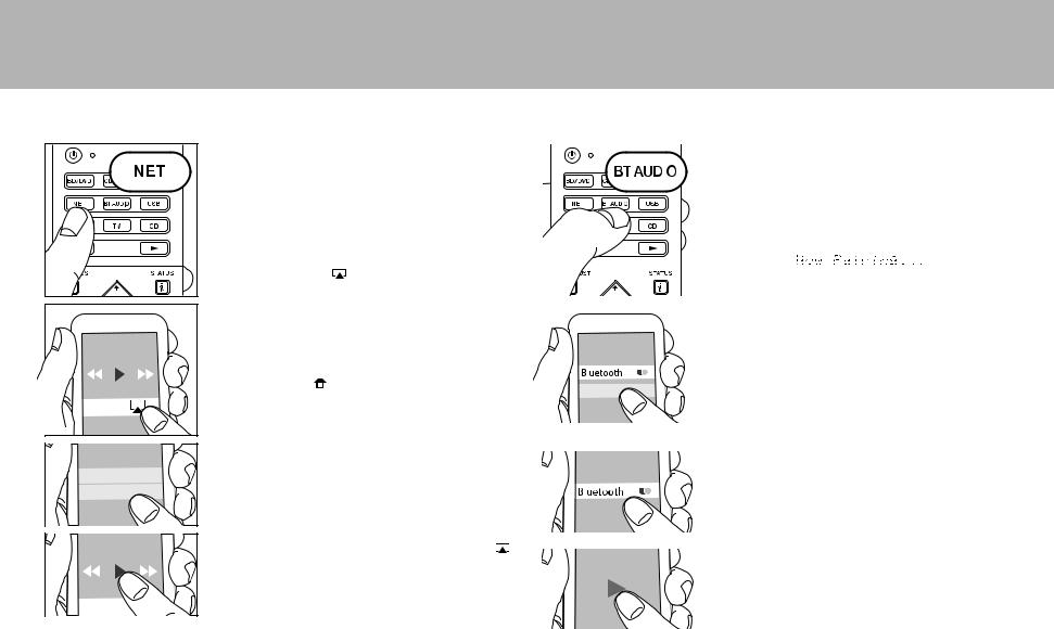
1. When you press BT AUDIO on the remote controller, |
|
||||
|
|
|
|
|
|
|
|
|
|
|
|
|
|
||||||
as this unit. |
|
|
|
|
|
|
|
|
|
|
|
|
|
|
"Now Pairing..." is displayed on this unit's display, and |
|
|||
|
|
|
|
|
|
|
|
|
|
|
|
|
|
|
|||||
|
|
|
|
|
|
|
|
|
|
|
|
|
|
|
|||||
0 Update the OS version on your iOS device to the latest |
|
|
|
|
|
|
|
|
|
|
|
|
|
the pairing mode is enabled. |
|
||||
version. |
|
|
|
|
|
|
|
|
|
|
|
|
|
|
|
|
|
|
|
1. Connect the iOS device to the access point. |
|
|
|
|
|
|
|
|
|
|
|
|
|
|
|
|
|
|
|
2. Press NET. |
|
|
|
|
|
|
|
|
|
|
|
|
|
|
|
|
|
|
|
3. Tap the AirPlay icon |
in the control center of the iOS |
|
|
|
|
|
|
|
|
|
|
|
|
|
|
|
|
|
|
|
|
|
|
|
|
|
|
|
|
|
|
|
2. Enable (turn on) the BLUETOOTH function of the |
|
|||||
device and select this unit from the list of devices |
|
|
|
|
|
|
|
|
|
|
|
|
|
|
|||||
displayed, and tap "Done". |
|
|
|
|
|
|
|
|
|
|
|
|
|
BLUETOOTH enabled device, then select this unit from |
|
||||
4. Play the music files on the iOS device. |
|
|
|
|
|
|
|
|
|
|
|
|
|
amongst the devices displayed. |
|
||||
0 The default status is for the Network Standby feature to |
|
|
|
|
|
|
|
|
|
|
|
|
|
If a password is requested, enter "0000". |
|
||||
be on, so when you do steps 3 and 4 above, this unit |
|
|
|
|
|
|
|
|
|
|
|
|
|
0 To connect another BLUETOOTH enabled device, press |
|
||||
automatically comes on and input switches to "NET". To |
|
|
|
|
|
|
|
|
|
|
|
|
|
and hold BT AUDIO until "Now Pairing..." is displayed, |
|
||||
reduce the amount of power consumed in standby |
|
|
|
|
|
|
|
|
|
|
|
|
|
then perform step 2 above. This unit can store the data |
|
||||
|
|
|
|
|
|
|
|
|
|
|
|
|
|
||||||
mode, press the |
button on the remote controller, |
|
|
|
VSX- |
|
of up to 8 paired devices. |
|
|||||||||||
then in the Home displayed set "System Setup" – |
|
|
|
|
0 The coverage area is 48 feet (15 meters). Note that |
|
|||||||||||||
|
|
|
|
|
|
|
|
|
|
|
|
|
|
||||||
"Hardware" – "Power Management" – "Network |
|
|
|
|
|
|
|
|
|
|
|
|
|
connection is not always guaranteed with all |
|
||||
Standby" to "Off". |
|
|
|
|
|
|
|
|
|
|
|
|
|
|
BLUETOOTH enabled devices. |
|
|||
|
|
|
|
|
|
|
|
|
|
|
|
|
|
|
|||||
0 Due to the characteristics of AirPlay wireless |
|
|
|
|
|
|
|
|
|
|
|
|
|
Playing Back |
|
||||
technology, the sound produced on this unit may slightly |
|
|
|
|
|
|
|
|
|
|
|
|
|
|
|||||
|
|
|
|
|
|
|
|
|
|
|
|
|
|
||||||
be behind the sound played on the AirPlay-enabled |
|
|
|
|
|
|
|
|
|
|
|
|
|
1. When the unit is on, connect the BLUETOOTH enabled |
|
||||
device. |
|
|
|
|
|
|
|
|
|
|
|
|
|
|
device. |
|
|||
You can also play back music files on the computer with |
|
|
|
|
|
|
|
|
|
|
|
|
|
2. The input selector of this unit will be automatically |
|
||||
|
|
|
|
|
|
|
|
|
|
|
|
|
|
||||||
|
|
|
|
|
|
|
|
|
|
|
|
|
switched to "BLUETOOTH". |
|
|||||
iTunes (Ver. 10.2 or later). Before operation, make sure |
|
|
|
|
|
|
|
|
|
|
|
|
|
3. Play music. Increase the volume of the BLUETOOTH |
|
||||
this unit and the PC are connected to the same network, |
|
|
|
|
|
|
|
|
|
|
|
|
|
enabled device to an appropriate level. |
|
||||
then press NET on this unit. Next, click the AirPlay icon |
|
|
|
|
|
|
|
|
|
|
|
|
|
0 Due to the characteristics of BLUETOOTH wireless |
|
||||
in iTunes, select this unit from the list of devices displayed, |
|
|
|
|
|
|
|
|
|
|
|
|
|
technology, the sound produced on this unit may slightly |
|
||||
and start play of a music file. |
|
|
|
|
|
|
|
|
|
|
|
|
|
be behind the sound played on the BLUETOOTH |
|
||||
|
|
|
|
|
|
|
|
|
|
|
|
|
|
||||||
|
|
|
|
|
|
|
|
|
|
|
|
|
|
|
enabled device. |
|
|||
|
|
|
|
|
|
|
|
|
|
|
|
|
|
|
|
|
|
|
|
|
|
|
|
|
|
|
|
|
|
|
|
|
|
|
|
|
|
|
|
23
> Before start > Hookup > Setup > Playback > Part Names
Others
a


b
c
d
e
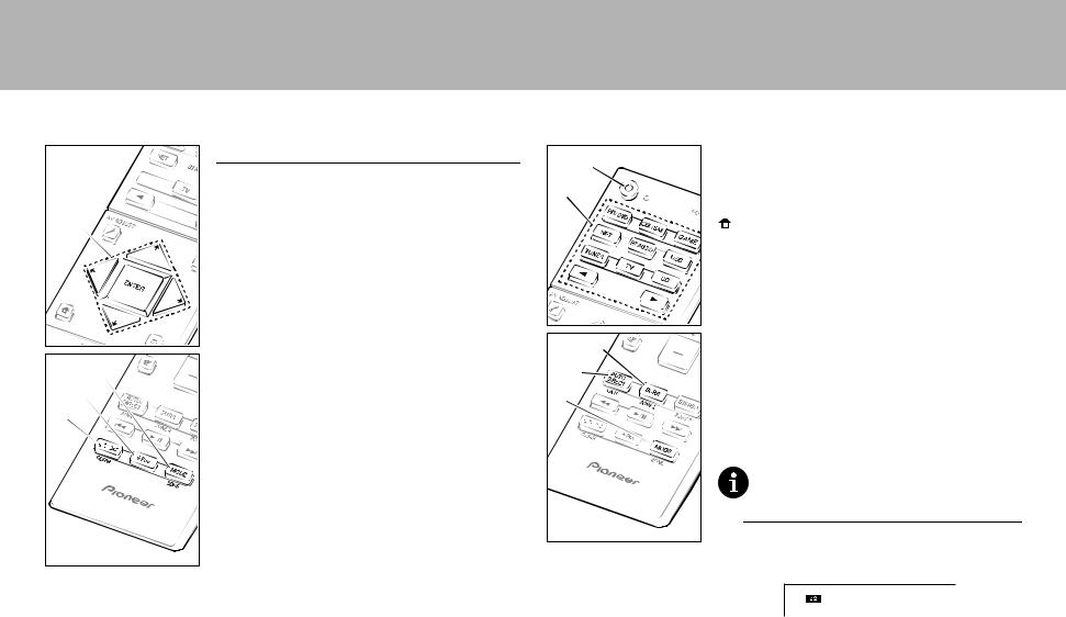
Listening To the Radio
1.Press TUNER (a) on the remote controller repeatedly to select either "AM" or "FM" on the display.
2.Press MODE (c) on the remote controller, so that the
"TunMode: Auto" is displayed on the display.
3. When you press the / cursor (b) buttons on the remote controller, automatic tuning starts, and searching stops when a station is found. When tuned into a radio station, the "TUNED" indicator on the display lights.
You can preset up to 40 stations.
1.Tune into the AM/FM radio station you want to register.
2.Press +Fav (d) on the remote controller so that the preset number on the display flashes.
3.While the preset number is flashing (about 8 seconds),
repeatedly press the / cursor (b) buttons on the remote controller to select a number between 1 and 40.
4.Press +Fav (d) again on the remote controller to register the station. When registered, the preset number stops
flashing. To select a preset radio station, press the / cursor (b) buttons on the remote controller.
0 To delete a preset station, press the / cursor (b) buttons on the remote controller to select the preset number you want to delete, press +Fav (d) on the remote controller and then press CLEAR (e) while the preset number is flashing. When deleted, the number on the display goes off.
Frequency step setting
Press the  button on the remote controller to select "System Setup" – "Miscellaneous" – "Tuner" – "AM/FM Frequency Step" and select the frequency step for your area. Note that when this setting is changed, all radio presets are deleted.
d |
Multi-zone |
||
|
|
||
If you haven't made the Multi Zone settings ( P20) in |
|||
e |
|||
Initial Setup, change the settings according to the audio |
|||
|
output method to the separate room (ZONE 2). Press the |
||
|
button on the remote controller and make the settings |
||
|
in System Setup accessed from the Home screen that is |
||
|
displayed. If you have connected speakers in a separate |
||
|
room with speaker cable, select "Zone 2" in "System |
||
|
Setup" "Speaker" "Configuration" "Zone Speaker". |
||
|
If you have connected a power amplifier in a separate |
||
|
room with an analog audio cable, then set "System Setup" |
||
|
"Multi Zone" "Zone 2" "Output Level" to "Variable" |
||
b |
if you want to be able to adjust the volume on this unit. |
||
c |
Play |
||
a |
1. While holding down MODE (a) on the remote controller, |
||
press ZONE 2 (b) for 3 or more seconds until the remote |
|||
|
indicator blinks twice. |
||
|
0 The remote controller switches to the mode for |
||
|
|
controlling ZONE 2. |
|
|
|
|
|
|
|
To return the remote controller to main room control |
|
|
|
mode: While holding down MODE (a) on the remote |
|
|
|
controller, press MAIN (c) for 3 seconds or more until the |
|
|
|
remote indicator flashes once. |
|
2.Point the remote controller at the main unit and press Í
(d).
"Z2" lights on the main unit display.
3.Press the input selector button (e) of the input to be played in the separate room. On the main unit, after pressing ZONE 2-CONTROL, within 8 seconds turn the input selector dial to select the input to be played in the separate room.
0 You can only select the same inputs for the main room and separate room with the "NET" or
24
> Before start > Hookup > Setup > Playback > Part Names
"BLUETOOTH", or "USB" input selector. If you have "NET" selected in the main room and then select "USB" in the separate room, the main room also switches to "USB". You cannot select different stations for the main room and separate room with the AM/FM radio.
4.To adjust the volume on this unit, adjust with VOL+/– on the remote controller. To control on the main unit, press ZONE 2-CONTROL and adjust with the MASTER
VOLUME control within 8 seconds.
0 If ZONE 2 is on, power consumption during standby becomes larger than normal.
To turn off the function
Press Í while in the mode for controlling ZONE 2 on the remote controller. Alternatively press ZONE 2-ON/OFF on the main unit.
Playing in ZONE 2 only
If you turn the unit to standby during multi-zone playback, the Z2 indicator is dimmed and the playback mode is switched to playback in a separate room only. Setting ZONE 2 to on while this unit is in standby will also switch the playback mode to the same setting.
AV Adjust
By pressing  on the remote controller during play, you can adjust frequently used settings, such as the switching the speakers and adjusting sound quality, using on-screen menus. Select the item with the cursors of the remote controller and press ENTER to confirm your selection. To return to the previous screen, press
  .
.
AV Adjust |
BD/DVD |
Tone Bass
Level Treble
MCACC
Other
"Tone": It is possible to enhance or moderate the bass and treble of front speakers. You can adjust the sound quality of the connected power amplifier when you turn ZONE 2 on. "Other": Enables you to make a variety of settings.
0"Sound Delay": If the video is behind the audio, you can delay the audio to offset the gap.
0"Sound Retriever": Improve the quality of compressed audio.
0"Speakers": You can switch the output on the surround back speakers and height speakers and switch the output for speakers A/B.
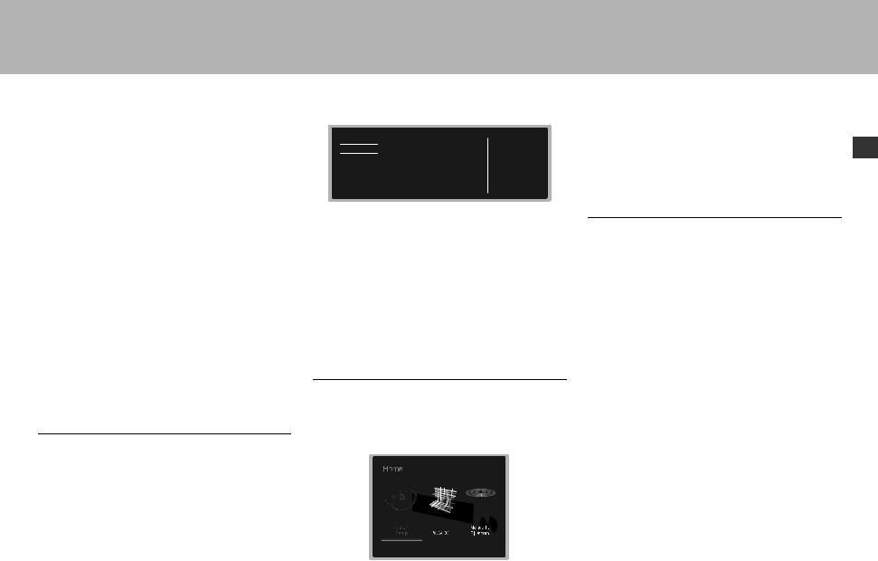
Home
When you press  on the remote controller, the Home is displayed and you can make settings in the various menus. Select the item with the cursors of the remote controller and press ENTER to confirm your selection. To return to the previous screen, press
  .
.
"System Setup": Advanced settings to provide you with an even better experience.
"MCACC": Setup the speakers automatically or make desired changes to the equalizer.
"Network/Bluetooth": Make Wi-Fi connection settings or En settings related to BLUETOOTH.
When the unit is operating erratically (Resetting this unit)
Restarting the unit may help it operate more smoothly. To restart the unit, turn it to standby, and then press
Í STANDBY/ON on the main unit for at least 5 seconds. (The unit’s settings will be maintained.) If there is no improvement even after the unit is restarted, try disconnecting and reconnecting the power cords of the unit and connected equipment. When there is still no improvement, resetting the unit to the status at the time of shipment may solve the problem. If you reset the unit status, your preferences will be reset to the defaults. Note them down before the operation below.
How to reset the unit
1.While holding down AUTO/DIRECT on the main unit, press Í STANDBY/ON on the main unit.
2."Clear" appears on the display and the unit returns to
standby. Do not unplug the power cord until "Clear" disappears from the display.
To reset the remote controller, while holding down MODE, press 
 until the remote indicator flash twice (about 3 seconds).
25
> Before start > Hookup > Setup > Playback > Part Names
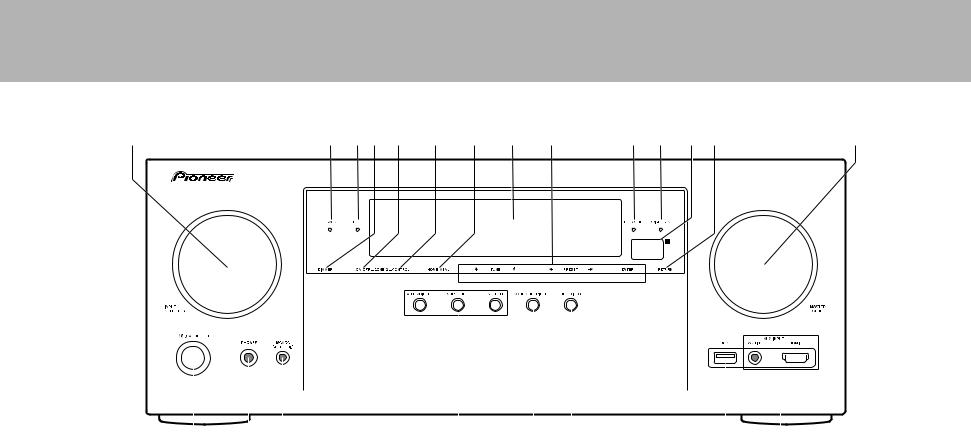
Front Panel
1 |
|
|
|
|
2 |
3 |
4 |
5 |
6 |
7 |
8 |
9 |
10 |
11 |
12 |
13 |
|
|
|
|
14 |
||||||||||
|
|
|
|
|
|
|
|
|
|
|
|
|
|
|
|
|
|
|
|
|
|
|
|
|
|
|
|
|
|
|
|
|
|
|
|
|
|
|
|
|
|
|
|
|
|
|
|
|
|
|
|
|
|
|
|
|
|
|
|
|
|
|
|
|
|
|
|
|
|
|
|
|
|
|
|
|
|
|
|
|
|
|
|
|
|
|
|
|
|
|
|
|
|
|
|
|
|
|
|
|
|
|
|
|
|
|
|
|
|
|
|
|
|
|
|
|
|
|
|
|
|
|
|
|
|
|
|
|
|
|
|
|
|
|
|
|
|
|
|
|
|
|
|
|
|
|
|
|
|
|
|
|
|
|
|
|
|
|
|
|
|
|
|
|
|
|
|
|
|
|
|
|
|
|
|
|
|
|
|
|
|
|
|
|
|
|
|
|
|
|
|
|
|
|
|
|
|
|
|
|
|
|
|
|
|
|
|
|
|
|
|
|
|
|
|
|
|
|
|
|
|
|
|
|
|
|
|
|
|
|
|
|
|
|
|
|
|
|
|
|
|
|
|
|
|
|
|
|
|
|
|
|
|
|
|
|
|
|
|
|
|
|
|
|
|
|
|
|
|
|
|
|
|
|
|
|
|
|
|
|
|
|
|
|
|
|
|
|
|
|
|
|
|
|
|
|
|
|
|
|
|
|
|
|
|
|
|
|
|
|
|
|
|
|
|
|
|
|
|
|
|
|
|
|
|
|
|
|
|
|
|
|
|
|
|
|
|
|
|
|
|
|
|
|
|
|
|
|
|
|
|
15 |
16 |
17 |
1.INPUT SELECTOR dial: Switch the input to be played.
2.MCACC indicator: This lights when you have enabled the speaker calibration made with MCACC.
3.FL OFF indicator: This lights when you have pressed DIMMER repeatedly to turn the display off.
4.DIMMER button: Switches the brightness of the display.
5.ZONE 2-ON/OFF button: Switches the multi-zone function on/off.
6.ZONE 2-CONTROL button: Controls the multi-zone function.
7.HOME MENU button: Displays the Home.
8.Display ( P28)
9. Cursor buttons ( TUNE / PRESET button) and ENTER button: Select the item with the cursors and press ENTER to confirm your selection. When using the TUNER, select the frequency with TUNE , or select
18 |
19 |
20 |
preset stations with PRESET .
10.NETWORK indicator: When the power of the unit is on, this lights when "NET" is selected with the input selector and the unit is connected to the network. If the unit is in standby mode, this lights when functions such as HDMI CEC and network standby are enabled. It does not light when ZONE 2 is on, however.
11.WIRELESS indicator: Lights when the unit is connected to the wireless network.
12.Remote control sensor
13.RETURN button: Returns the display to the previous state.
14.MASTER VOLUME: Allows you to adjust the volume.
15.Í STANDBY/ON button: Turns the unit on or into standby mode.
16.PHONES jack: Stereo headphones with a standard plug
21 22
(1/4 inch or ø6.3 mm) are connected.
17.MCACC SETUP MIC jack: The supplied speaker setup microphone is connected.
18.Listening mode button: Select the listening mode.
19.SOUND RETRIEVER button: Turns on/off the Sound Retriever function that provides better sound quality for compressed audio.
20.PURE DIRECT button: Swithes to the Pure Direct mode.
21.USB port: A USB storage device is connected so that music files stored in it can be played. You can also supply power (5V/1A) to USB devices with a USB cable.
22.AUX INPUT AUDIO/HDMI jack: A video camera or such other device is connected.
26
> Before start > Hookup > Setup > Playback > Part Names
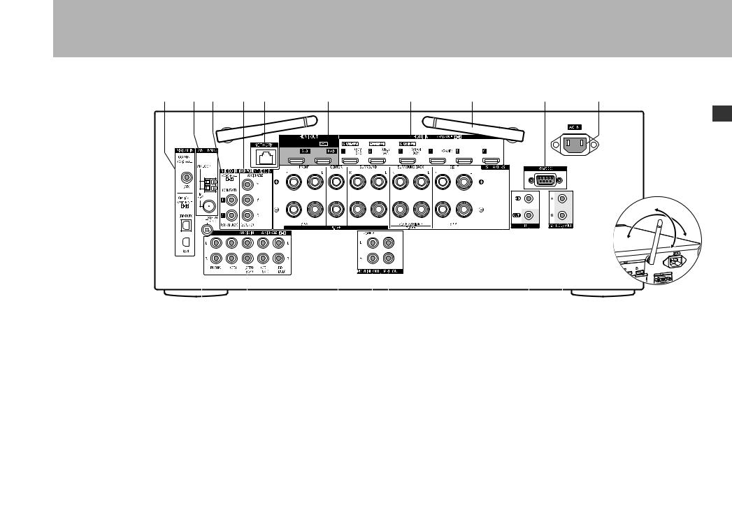
Rear Panel
1 |
2 |
3 |
4 |
5 |
6 |
7 |
8 |
9 |
10 |
En
8
90°
180°
|
|
|
|
|
|
|
|
|
|
|
|
|
|
|
|
|
|
|
|
|
|
|
|
|
|
|
|
|
|
|
|
|
|
|
|
|
|
|
|
|
|
|
|
|
|
|
|
|
|
|
|
|
|
|
|
|
|
|
|
|
|
|
|
|
|
|
|
|
|
|
|
|
|
|
|
|
|
|
|
|
|
|
|
|
|
|
|
|
|
|
|
|
|
|
|
|
|
|
|
|
|
|
|
|
|
|
|
|
|
|
|
|
|
|
|
|
|
|
|
|
|
|
|
|
|
|
|
|
|
|
|
|
|
|
|
|
|
|
|
|
|
|
|
|
|
|
|
|
|
|
|
|
|
|
|
|
|
|
|
|
|
|
|
|
|
|
|
|
|
|
|
|
|
|
|
|
|
|
|
|
|
|
|
|
|
|
|
|
|
|
|
|
|
|
|
|
|
|
|
|
|
|
|
|
|
|
|
|
|
|
|
|
|
|
|
|
|
|
|
|
|
|
|
|
|
|
|
|
|
|
|
|
|
|
|
|
|
|
|
|
|
|
|
|
|
|
|
|
|
|
|
|
|
|
|
|
|
|
|
|
|
|
|
|
|
|
|
|
|
|
|
|
|
|
|
|
|
|
|
|
|
|
|
|
|
|
|
|
|
|
|
|
|
|
|
|
|
|
|
|
|
|
|
|
|
|
|
|
|
|
|
|
|
|
|
|
|
|
|
|
|
|
|
|
|
|
|
|
|
|
|
|
|
|
|
|
|
|
|
|
|
|
|
|
|
|
|
|
|
|
|
|
|
|
|
|
|
|
|
|
|
|
|
|
|
|
|
|
|
|
|
|
|
|
|
|
|
|
|
|
|
|
|
|
|
|
|
|
|
|
|
|
|
|
|
|
|
|
|
|
|
|
|
|
|
|
|
|
|
|
|
|
|
|
|
|
|
|
|
|
11 |
|
|
|
|
|
12 |
|
|
|
|
|
|
|
13 |
|
|
14 |
15 |
|
|
16 |
17 |
|
|||||||||||||||||
1. |
DIGITAL IN OPTICAL/COAXIAL jacks: Input TV or AV |
with a HDMI cable connected to an AV component. |
|
powered amplifier in a separate room (ZONE 2). |
|||||||||||||||||||||||||||||||||||||
|
component digital audio signals with a digital optical |
8. Wireless antenna: Used for Wi-Fi connection or when |
15.SUBWOOFER PRE OUT jack: Connect a powered |
||||||||||||||||||||||||||||||||||||||
|
cable or digital coaxial cable. |
|
|
|
|
|
|
|
|
|
|
|
using a BLUETOOTH enabled device. Adjust their |
|
subwoofer with a subwoofer cable. Up to two powered |
||||||||||||||||||||||||||
2. |
ANTENNA AM LOOP/FM 75Ω terminal: The supplied |
angles according to the connection status. |
|
subwoofers can be connected. The same signal is output |
|||||||||||||||||||||||||||||||||||||
|
antennas are connected. |
|
|
|
|
|
|
|
|
|
|
|
9. RS-232C port: For connection to the home control |
|
from each of the SUBWOOFER PRE OUT jacks. |
||||||||||||||||||||||||||
3. |
VIDEO IN jacks: Input the AV component video signals |
system. |
|
|
|
|
|
|
|
16.IR IN/OUT port: Allows you to connect a multiroom |
|||||||||||||||||||||||||||||||
|
with an analog video cable. |
|
|
|
|
|
|
|
|
|
|
|
10.AC IN: The supplied power cord is connected. |
|
remote control kit. |
||||||||||||||||||||||||||
4. |
COMPONENT VIDEO IN jacks: Input the AV component |
11.SIGNAL GND terminal: The ground wire of the turntable |
17.12V TRIGGER OUT A/B jacks: Allows you to connect a |
||||||||||||||||||||||||||||||||||||||
|
video signals with a component video cable. |
|
|
|
|
|
|
|
|
|
|
|
is connected. |
|
|
|
|
|
|
|
|
device with 12V trigger input jack to enable link operation |
|||||||||||||||||||
5. |
NETWORK port: Connect to the network with an |
12.AUDIO IN jacks: Input AV component audio signal with |
|
between the device and the unit. |
|||||||||||||||||||||||||||||||||||||
|
Ethernet cable. |
|
|
|
|
|
|
|
|
|
|
|
an analog audio cable. |
|
|
|
|
|
|
|
|
|
|
|
|||||||||||||||||
6. |
HDMI OUT jacks: Transmit video signals and audio |
13.SPEAKERS terminals: Connect speakers with speaker |
|
|
|
|
|
|
|
||||||||||||||||||||||||||||||||
|
signals with a HDMI cable connected to a monitor such |
cables. |
|
|
|
|
|
|
|
|
|
|
|
|
|
|
|||||||||||||||||||||||||
|
as a TV or projector. |
|
|
|
|
|
|
|
|
|
|
|
14.ZONE 2 PRE/LINE OUT jack: Output audio signals with |
|
|
|
|
|
|
|
|||||||||||||||||||||
7. |
HDMI IN jacks: Transmit video signals and audio signals |
an analog audio cable to a pre-main amplifier or a |
|
|
|
|
|
|
|
||||||||||||||||||||||||||||||||
27
> Before start > Hookup > Setup > Playback > Part Names
Remote Controller
1.Í button: Turns the unit on or into standby mode.
2.Input selector buttons: Switches the input to be played.
3.21 button: Select the input to be played.
4. (AV ADJUST) button: You can perform common settings on
1 |
|
the TV screen. |
||
5. |
Cursor buttons and ENTER button: Select the item with the |
|||
|
||||
|
|
cursors and press ENTER to confirm your selection. |
||
2 |
6. |
button: Displays the Home. |
||
7. |
Volume buttons: Allows you to adjust the volume. This button |
|||
|
|
also cancels the muting. |
||
|
8. |
button: Temporarily mutes audio. Press again to cancel |
||
3 |
9. |
muting. |
|
|
|
LISTENING MODE buttons: Allows you to select the listening |
|||
|
12 |
mode. |
|
|
4 |
MAIN/ZONE 2 buttons: Controls the multi-zone function. |
|||
|
|
(The ZONE 3 button is not used with this unit.) |
||
|
10.Play button: Used for play operations when playing Music Server |
|||
5 |
|
or USB. |
|
|
11. |
button: Used for repeat or random play operations when |
|||
|
||||
|
|
playing Music Server or USB. |
||
6 |
13 |
CLEAR button: Deletes all characters you have entered when |
||
entering text on the TV screen. |
||||
|
|
|||
12. (STATUS) button: Switches the information on the display.
13. button: Returns the display to the previous state.
14.MODE button: Switches tuning to a station between automatic
7 |
|
tuning and manual tuning. |
|
15.+Fav button: Registers a radio station. |
|
8 |
|
|
|
|
|
9 |
|
|
10 |
|
30° |
11 |
14 |
30° |
|
15 |
Approx.5 m |
|
|
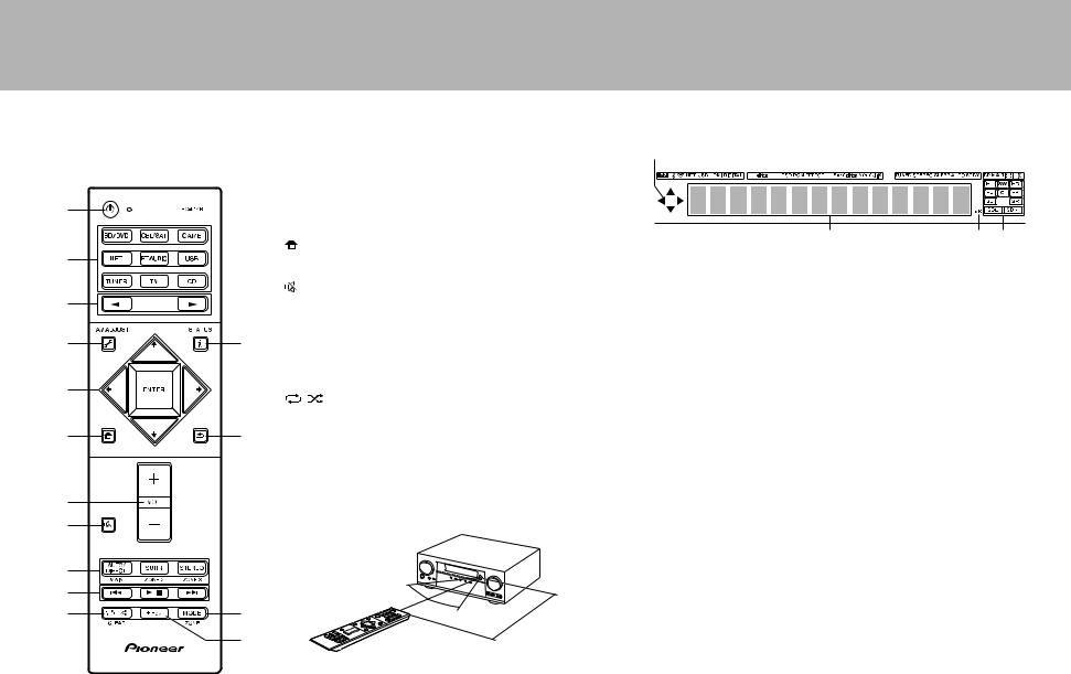
Display
1 |
2 |
3 |
4 |
5 6 7 |
|||||||||
|
|
|
|
|
|
|
|
|
|
|
|
|
|
|
|
|
|
|
|
|
|
|
|
|
|
|
|
|
|
|
|
|
|
|
|
|
|
|
|
|
|
8 |
9 |
10 |
1.This may light when performing operations with the "NET", "USB" input selector.
2.Lights in the following conditions. Z2: When ZONE 2 is on.
 : When connected by BLUETOOTH.
 : When connected by Wi-Fi.
NET: When "NET" is selected with the input selector and the unit is connected to the network. It will flash if the connection to the network is not correct.
USB: When "USB" is selected with the input selector and the unit is connected by USB and the USB device is selected. Flashes if the USB is not properly connected.
HDMI: When HDMI signals are input and the HDMI input is selected. DIGITAL: When digital signals are input and the digital input is selected.
3.Lights according to the type of input digital audio signals and the listening mode.
4.Lights in the following conditions. TUNED: Receiving AM/FM radio. STEREO: Receiving FM stereo.
SLEEP: When the sleep timer is set. AUTO STBY: Auto Standby is on.
5.The currently selected speaker system lights.
6.Lights when headphones are connected.
7.Flashes when muting is on.
8.Displays various information of the input signals.
9.Lights when adjusting the volume.
10.Speaker/Channel display: Displays the output channel that corresponds to the selected listening mode.
28
 Loading...