


Pioneer VSX-D912-K, VSX-D912-S, VSX-D812-S, VSX-D712-K, VSX-D812-K Manual
...AUDIO/VIDEO MULTI-CHANNEL RECEIVER
RECEPTOR AUDIO/VÍDEO
MULTICANAL
VSX-D712-S/-K VSX-D812-S/-K VSX-D912-S/-K
Operating Instructions Manual de instrucciones

TWO VOLTAGE SELECTOR SWITCHES
Only multi-voltage model is provided with these switches. Mains voltages in Saudi Arabia are 127 V and 220 V only. Never use this model with the 110 V setting in Saudi Arabia.
The line voltage selector switches are on the rear panel. Check that they are set properly before plugging the power cord into the household wall socket. If the voltage is not properly set or if you move to an area where the voltage requirements differ, adjust the selector switches as follows.
1.Use a medium-size screwdriver.
2.First, insert the screwdriver in the groove of the voltage selector at the right, and adjust so that the tip of the groove points to the voltage value of your area.
3.Next, insert the screwdriver in the groove of the voltage selector at the left and adjust until the voltage is the same as at the right.
TWO VOLTAGE SELECTORS
110V |
|
|
|
|
220V |
|
120-127V |
|
|
|
|
|
240V |
|
|
|
|
|
|
|
|
|
|
|
|
|
|
220V |
240V |
110V |
120– |
|
127V |
Medium-size screwdriver

Thank you for buying this Pioneer product.
Please read through these operating instructions so that you will know how to operate your model properly. After you have finished reading the instructions, put them in a safe place for future reference.
01 Before you start |
|
Operating other Pioneer components . . . . |
27 |
Checking what’s in the box . . . . . . . . . . . . |
5 |
05 Controls and displays |
|
Installing the receiver. . . . . . . . . . . . . . . . . |
5 |
|
|
Making cable connections . . . . . . . . . . . . . |
5 |
Front panel . . . . . . . . . . . . . . . . . . . . . . . . |
28 |
Loading the batteries . . . . . . . . . . . . . . . . . |
5 |
Display . . . . . . . . . . . . . . . . . . . . . . . . . . . |
30 |
Operating range of remote control unit . . . |
6 |
Remote control . . . . . . . . . . . . . . . . . . . . . |
32 |
English
02 5 minute guide
Introduction to home theater . . . . . . . . . . . 7 Listening to Surround Sound . . . . . . . . . . . 8 Using the Quick Setup . . . . . . . . . . . . . . . 12
03 Quick surround sound setup
(VSX-D912 only)
Automatically calibrating your listening
area (MCACC) . . . . . . . . . . . . . . . . . . . . . 14
04 Connecting up
Audio/Video cords . . . . . . . . . . . . . . . . . . 16 S-video cables . . . . . . . . . . . . . . . . . . . . . 16
Component video cords . . . . . . . . . . . . . . 16 Digital audio coaxial cords/
Optical cables . . . . . . . . . . . . . . . . . . . . . 16
Connecting digital components . . . . . . . . 17 Connecting audio components . . . . . . . . 18 Connecting DVD multi-channel
components . . . . . . . . . . . . . . . . . . . . . . . 19
Connecting video components. . . . . . . . . 20 Connecting to the front panel video terminal . . . . . . . . . . . . . . . . . . . . . . . . . 20
Connecting antennas. . . . . . . . . . . . . . . . 21
FM wire antenna . . . . . . . . . . . . . . . . . . 21 AM loop antenna . . . . . . . . . . . . . . . . . . 21
Using external antennas . . . . . . . . . . . . 21 Connecting the speakers (VSX-D712) . . . . 22 Connecting the speakers
(VSX-D812/D912) . . . . . . . . . . . . . . . . . . . 23 Speaker terminals . . . . . . . . . . . . . . . . . 24
A and B speaker systems. . . . . . . . . . . . 24 Hints on speaker placement . . . . . . . . . 24 Connecting additional amplifiers . . . . . . . 26
Power cord caution . . . . . . . . . . . . . . . . 27
06 Playing sources
Introduction to Sound Modes . . . . . . . . . .35
Stereo/Direct. . . . . . . . . . . . . . . . . . . . . . 35 Standard mode . . . . . . . . . . . . . . . . . . . . 35
Advanced Surround modes. . . . . . . . . . .36 Choosing the input signal . . . . . . . . . . . . .36 Listening to multi-channel playback . . . . .37
Using Stereo/Direct . . . . . . . . . . . . . . . . . . 38
Using Advanced Surround . . . . . . . . . . . .38 Using the Surround Back Channel
(SB CH) . . . . . . . . . . . . . . . . . . . . . . . . . . . 39
Using the Virtual Surround Back mode (VSB) . . . . . . . . . . . . . . . . . . . . . . . . . . . . . 40
Using Midnight and Loudness listening . .41 Using the tone controls . . . . . . . . . . . . . . .41 Playing other sources . . . . . . . . . . . . . . . .41 Selecting the multi-channel analog
inputs . . . . . . . . . . . . . . . . . . . . . . . . . . . . 42
Using the sleep timer . . . . . . . . . . . . . . . .42
07 Setting up
Choosing your receiver setup . . . . . . . . . .43
Speaker setting . . . . . . . . . . . . . . . . . . . . 44
Surround back speaker setting . . . . . . . .45
Subwoofer setting . . . . . . . . . . . . . . . . . . 45
Crossover frequency setting . . . . . . . . . .45 LFE attenuator setting . . . . . . . . . . . . . . .46 Front left speaker distance setting . . . . .46 Center speaker distance setting . . . . . . .46 Front right speaker distance setting . . . .47 Surround right speaker distance
setting. . . . . . . . . . . . . . . . . . . . . . . . . . . 47
Surround back speaker distance
setting. . . . . . . . . . . . . . . . . . . . . . . . . . . 47
Español Nederlands Deutsch Français Italiano

Surround left speaker distance
setting . . . . . . . . . . . . . . . . . . . . . . . . . . 47
Subwoofer distance setting . . . . . . . . . . 47 Dynamic range control setting. . . . . . . . 48
Dual mono setting . . . . . . . . . . . . . . . . . 48
Component video input settings . . . . . . 48 Surround back channel input setting (VSX-D812/D912 only) . . . . . . . . . . . . . . 49 Digital input settings . . . . . . . . . . . . . . . 49
Manually calibrating your listening area (MCACC) . . . . . . . . . . . . . . . . . . . . . . . . . 50
Setting separate channel levels for
listening modes . . . . . . . . . . . . . . . . . . . . 51
08 Using the tuner
Listening to the radio . . . . . . . . . . . . . . . . 53 Improving FM stereo sound . . . . . . . . . . 53 Tuning directly to a station. . . . . . . . . . . 53 Saving station presets . . . . . . . . . . . . . . . 54 Naming station presets . . . . . . . . . . . . . 55 Listening to station presets . . . . . . . . . . 56 Changing the frequency step . . . . . . . . . 56
09 Making recordings
Making an audio or a video recording . . . 57
10 Controlling the rest of your system
Setting the remote to control other components . . . . . . . . . . . . . . . . . . . . . . . 58
Selecting preset codes directly. . . . . . . . . 58
Programming signals from other remote controls (VSX-D812/D912 only) . . . . . . . . .59 Erasing all of your programmed settings (VSX-D812/D912 only) . . . . . . . . . . . . . . . .60 Clearing all the remote control settings . . .60
Direct function . . . . . . . . . . . . . . . . . . . . . 60 Controls for TVs . . . . . . . . . . . . . . . . . . . . . 61
Controls for other components . . . . . . . . .62 Preset Code List (VSX-D712 only). . . . . . . .64 Preset Code List (VSX-D812/D912). . . . . . .65
11 Additional information
Troubleshooting . . . . . . . . . . . . . . . . . . . . 67
Resetting the main unit . . . . . . . . . . . . . . .69
Specifications . . . . . . . . . . . . . . . . . . . . . . 70
"DTS" ,"DTS-ES Extended Surround" and "Neo:6" are trademarks of Digital Theater Systems, Inc.
Manufactured under license from Dolby Laboratories. "Dolby", "Pro Logic", "Surround EX", and the double-D symbol are trademarks of Dolby Laboratories.
Before you start
Chapter 1:
Before you start
Checking what’s in the box
Please check that you've received the following supplied accessories:
•AM loop antenna
•FM wire antenna
•Power cord (not applicable to the Singapore and Malaysia models) x2
VSX-D712/D812/D912-K
ROUND 2P type and Australian type VSX-D712/D812/D912-S
ROUND 2P type and Straight type
•J shape plug (VSX-D712/D812/D912-K only) x 1
•Dry cell batteries (AA size IEC R6) x2
•Remote control
•Microphone (VSX-D912 only)
•Microphone stand (VSX-D912 only)
•These operating instructions
Installing the receiver
Please note the following points:
•Do not place objects directly on top of this unit. This prevents proper heat dispersal.
•When installing on a rack, shelf, etc., be sure to leave more than 20 cm. of space above the receiver.
Making cable connections
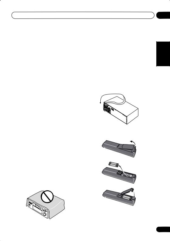
Make sure not to bend the cables over the top of this unit (as shown in the illustration). If this happens, the magnetic field produced by the transformers in this unit may cause a humming noise from the speakers.
Loading the batteries
01
Español Nederlands Deutsch Français Italiano English
5
En

01 Before you start
Incorrect use of batteries may result in such hazards as leakage and bursting. Observe the following precautions:
•Never use new and old batteries together.
•Insert the plus and minus sides of the batteries properly according to the marks in the battery case.
•Batteries with the same shape may have different voltages. Do not use different batteries together.
•When disposing of used batteries, please comply with governmental regulations or environmental public instruction’s rules that apply in your country or area.
Operating range of remote control unit
The remote control may not work properly if:
•There are obstacles between the remote control and the receiver's remote sensor.
•Direct sunlight or fluorescent light is shining onto the remote sensor.
•The receiver is located near a device that is emitting infrared rays.
•The receiver is operated simultaneously with another infrared remote control unit.
30
30
7m
6
En

5 minute guide
Chapter 2:
5 minute guide
Introduction to home theater
You are probably used to using stereo equipment to listen to music, but may not be used to home theater systems that give you many more options (such as surround sound) when listening to soundtracks.
Home theater refers to the use of multiple audio tracks to create a surround sound effect, making you feel like you're in the middle of the action or concert. The surround sound you get from a home theater system depends not only on the speakers you have set up in your room, but also on the source and the sound settings of the receiver.
DVD-Video has become the basic source material for home theater due to its size, quality, and ease of use. Depending on the DVD, you can have up to seven different audio tracks coming from one disc, all of them being sent to different speakers in your system. This is what creates a surround sound effect and gives you the feeling of ‘being there’.
This receiver will automatically decode Dolby Digital, DTS, or Dolby Surround DVD-Video discs, according to your speaker setup. In most cases, you won’t have to make changes for realistic surround sound, but other possibilities (like listening to a CD with multi-channel surround sound) are explained in Playing sources on page 35.
02
Español Nederlands Deutsch Français Italiano English
7
En
02 5 minute guide
Listening to Surround Sound
This receiver was designed with the easiest possible setup in mind, so with the following quick setup guide, you should have your system hooked up for surround sound in no time at all. In most cases, you can simply leave the receiver in the default settings.
Be sure to complete all connections before connecting this unit to the AC power source.
1 Hook up your DVD player.
For surround sound, you’ll want to hook up using a digital connection from the DVD player to the receiver. You can do this with either a coaxial, or an optical connection (you don’t need to connect both). If you hook up using an optical cable, you should refer to Digital input settings on page 49 to assign the optical input to DVD.
Use a video cord to connect the video output on your DVD player to the receiver using the jacks shown below.
2 Hook up your TV.
Use a video cord to connect your receiver to the TV using the jacks as shown below.
 Optical cable
VIDEO IN
TV
Video cord
|
|
DIGITAL |
|
|
|
OUT |
OPT |
|
|
|
|
DIGITAL OUT |
Coaxial |
|
OPT |
|
|
2 |
|
|
cable |
(CD-R/TAPE/MD) |
|
|
|
|
OPT |
|
|
|
1 |
|
|
|
(TV / |
|
|
|
SAT) |
|
|
ASSIGNABLE |
COAX |
|
|
DIGITAL |
2 |
|
|
IN |
(CD) |
|
|
|
|
|
|
|
COAX |
|
|
|
1 |
|
|
|
(DVD |
|
|
|
/LD) |
DVD player
VIDEO OUT
S
|
|
|
|
|
|
|
|
|
|
|
|
|
|
|
|
This receiver* |
|
|||||||
|
|
|
|
|
AM |
FM UNBAL |
|
CEN- |
SUB W. |
|
DVD |
|
|
|
|
|
|
|
|
|
|
|
|
|
|
|
|
|
|
|
TER |
|
|
|
|
|
|
|
|
|
|
|
|
|
|
||||
|
|
|
|
|
LOOP |
75 Ω |
|
|
|
|
7.1CH |
|
|
|
|
|
|
|
|
|
|
|
|
|
|
|
IN |
|
AUX |
|
|
|
|
|
|
INPUT |
|
|
|
|
|
|
|
|
|
|
|
TWO VOLTAGE SELECTOR |
|
DIGITAL |
|
|
|
|
|
|
|
|
|
|
|
COMPONENT |
ASSIGNABLE |
(DVD/LD) IN 1 |
|
|
L |
L |
SURROUND |
|
110 V |
220 V |
||
|
|
|
|
|
|
|
|
|
SURROUND |
|
VIDEO |
|
|
|
|
BACK |
|
120 - 127 V |
240 V |
|||||
OUT |
|
IN |
|
CD |
|
|
|
|
|
MONITOR OUT |
|
|
|
|
|
|
|
|
|
|
|
|||
|
OPT |
|
ANTENNA |
MONITOR |
OUT |
R |
|
L |
|
|
|
|
|
|
|
|
|
|
|
|
||||
|
OPT |
OUT |
|
VCR / |
OUT |
IN |
|
R |
|
L |
|
|
|
|
|
|
|
|
|
|
|
|
|
|
|
2 |
|
|
DVR |
|
|
|
SURROUND BACK |
|
Y |
|
PB |
PR |
Y |
PB |
PR |
|
R |
R |
|
|
|
|
|
|
|
|
|
|
|
CONTROL |
|
|
|
|
|
|
|
|
||||||||||
(CD-R/TAPE/MD) |
IN |
|
|
VIDEO |
|
OUT |
|
|
|
|
|
|
|
|
(TV/SAT) IN 2 |
|
|
FRONT |
SURROUND |
CENTER |
|
|
|
|
|
OPT |
|
|
TV / |
OUT |
VCR/ |
S |
|
R |
FRONT |
L |
CENTER |
R SURROUND BACK |
L |
R |
SURROUND L |
R |
FRONT |
L |
|||||
|
1 |
|
|
IN |
DVR |
|
||||||||||||||||||
|
(TV / |
IN |
|
SAT |
|
|
IN |
P |
|
|
VIDEO |
|
|
|
|
|
|
|
|
|
|
|
|
|
|
SAT) |
|
|
IN |
|
|
|
|
|
|
|
|
|
|
|
|
|
|
|
|
|
|
||
ASSIGNABLE |
COAX |
|
|
DVD |
|
MONITOR |
T V / |
E |
|
|
|
|
|
|
OUT |
|
|
|
|
|
|
|
|
|
DIGITAL |
2 |
|
|
/ LD |
|
|
|
|
|
|
|
|
|
|
|
|
|
|
|
|
||||
|
|
FRONT |
|
OUT |
SAT |
A |
|
|
|
|
|
|
|
|
|
|
|
|
|
|
|
|||
IN |
(CD) |
IN |
|
D V D |
|
IN |
A |
|
|
|
|
|
|
SINGLE |
|
|
|
|
|
|
|
B |
||
|
|
|
|
|
|
|
|
|
|
|
|
|
|
INSTRUCTION |
|
|
|
|
|
|
||||
|
COAX |
|
|
REC |
7.1CH |
SUB |
|
K |
|
|
|
|
|
|
SEE MANUAL |
|
|
|
|
|
|
|
||
|
|
|
INPUT |
DVD / |
|
|
|
|
|
|
|
|
|
|
|
|
|
|
|
|
||||
|
1 |
|
|
|
IN |
WOOFER |
E IN |
|
|
|
|
|
|
|
|
|
|
|
|
|
|
|
||
|
(DVD |
OUT |
|
CD-R |
PREOUT |
LD |
|
|
|
|
|
MONITOR |
|
|
|
|
|
|
|
|
||||
|
|
/ TAPE |
|
IN |
|
|
|
|
|
|
|
|
|
|
|
|
|
|
|
|||||
|
/LD) |
|
|
/ MD |
|
|
R |
|
|
|
|
|
|
|
|
|
|
|
|
|
|
|||
|
|
|
|
|
|
S-VIDEO |
|
|
|
|
|
|
|
OUT |
|
|
|
|
|
|
|
|
|
|
|
|
IN |
|
PLAY |
|
|
S |
|
|
|
|
|
|
|
|
|
|
|
|
|
|
|
||
|
|
R |
AUDIO |
L |
|
|
|
|
|
|
|
|
|
|
|
|
|
|
|
|
|
|
|
|
|
|
|
|
|
|
|
|
|
|
|
|
|
|
|
SUB |
|
|
|
|
|
|
|
|
|
|
|
|
|
|
|
|
|
|
|
|
|
|
|
|
WOOFER |
|
|
|
|
|
|
|
|
|
|
DVD |
|
IN |
|
|
|
|
|
|
|
|
|
|
PREOUT |
|
|
|
|
|
|
|
|
||
|
|
|
|
|
|
|
|
|
|
|
|
|
|
|
|
|
|
|
|
|
|
|||
/ LD
FRONT
D V D 7.1CH REC INPUT
CD-R IN / TAPE
/ MD
 Video cord
* The illustration shows the VSX-D812/D912, but connections for the VSX-D712 are the same.
8
En

5 minute guide |
02 |
3 Connect your speakers.
A complete setup of speakers is shown here (six speakers for the VSX-D712, and eight for the VSX-D812/D912), but everyone’s home setup will vary. Simply connect the speakers you have in the manner shown below. The receiver will work with just two stereo speakers (the front speakers in the diagram) but using at least three speakers is recommended, and a complete setup is best.
Make sure you connect the speaker on the right to the right terminal and the speaker on the left to the left terminal. Also make sure the positive and negative (+/–) terminals on the receiver match those on the speakers.
•Use speakers with a nominal impedance of 8 Ω to 16 Ω.
•If you’re not using a subwoofer, change the front speaker setting (see Speaker setting on page 44) to large.
Front speakers |
Center speaker |
Surround speakers |
||
L |
R |
C |
LS |
RS |
Français Italiano English
AM |
FM UNBAL |
|
LOOP |
COMPONENT |
|
|
1 |
|
|
VIDEO |
|
OUT |
MONITOR OUT |
|
|
|
|
|
|
|
|
|
MONITOR |
OUT |
|
|
|
|
|
|
|
|
|
|
|
|
|
|
|
|
|
|
|
|
SURROUND |
|
|
|
|
|
|
|
|
|
|
|
|
|
OUT |
|
VCR / |
OUT |
IN |
|
DVD 5.1CH INPUT |
|
|
|
|
|
|
|
|
|
|
|
|
|
|
|
|
|
|
|
|
|
|
|
|
|
|
|
||||
|
|
|
|
DVR |
|
|
|
|
|
Y |
PB |
PR |
Y |
PB |
PR |
|
|
|
|
|
|
|
|
|
|
CONTROL |
|
|
|
|
|
|
|
||||||
|
|
IN |
|
|
|
OUT |
|
|
|
|
|
|
(TV/SAT) IN 2 |
|
|
|
|
|
|
|
OPT |
|
|
|
VIDEO |
|
|
FRONT |
|
CENTER |
|
|
SURROUND |
|
|
FRONT |
|
||
|
|
|
|
IN |
VCR/ |
S |
R |
L |
|
R |
L |
R |
L |
||||||
|
1 |
|
|
TV / |
OUT |
DVR |
|
||||||||||||
|
(TV / |
IN |
|
SAT |
|
|
IN |
P |
|
|
|
|
|
|
|
|
|
|
|
|
SAT) |
|
|
IN |
|
|
|
|
|
|
|
|
|
|
|
|
|
||
ASSIGNABLE |
COAX |
|
|
DVD |
|
|
E |
|
|
|
|
|
|
|
|
|
|
|
|
|
|
|
MONITOR |
T V / |
|
|
|
|
|
|
|
|
|
|
|
||||
DIGITAL |
2 |
|
|
/ LD |
|
|
|
|
|
|
|
|
|
|
|
|
|
||
|
|
FRONT |
|
OUT |
SAT |
A |
|
|
|
|
|
|
|
|
|
|
|
||
IN |
(CD) |
IN |
|
|
IN |
A |
|
|
|
|
|
|
|
|
|
B |
|||
|
|
D V D |
|
|
|
|
|
|
|
|
|
|
|||||||
|
COAX |
|
|
REC |
5.1CH |
SUB |
|
K |
|
|
|
|
|
|
|
|
|
|
|
|
|
|
INPUT |
WOOFER |
DVD / |
E |
|
|
|
|
|
|
|
|
|
|
|
||
|
1 |
|
|
|
IN |
|
|
|
|
|
|
|
|
|
|
|
|||
|
OUT |
|
CD-R |
PREOUT |
LD |
|
|
|
|
|
|
|
|
|
|
|
|||
|
(DVD |
|
/ TAPE |
|
IN |
R |
|
|
|
|
|
|
|
|
|
|
|
||
|
/LD) |
|
|
/ MD |
|
SURROUND |
|
|
|
|
|
|
|
|
|
|
|
||
|
|
|
|
|
|
BACK |
|
|
|
|
|
|
|
|
|
|
|
|
|
|
|
IN |
AUDIO |
PLAY |
|
S-VIDEO |
|
S |
|
|
|
|
|
|
|
|
|
|
|
|
|
R |
L |
|
|
|
|
|
|
|
|
|
|
|
|
|
|
|
|
VSX-D712
Powered subwoofer SW
Español Nederlands Deutsch
9
En

02 5 minute guide
Front speakers |
Center speaker |
Surround speakers |
Surround back speakers |
|||||||||||
L |
|
R |
|
C |
LS |
|
RS |
|
SBL |
SBR |
||||
|
|
|
|
|
|
|
|
|
|
|
|
|
|
|
|
|
|
|
|
|
AM |
FM UNBAL |
|
CEN- |
SUB W. |
|
DVD |
|
|
|
|
|
|
|
|
|
|
|
|
|
|
|
|
|
|
|
|
|
TER |
|
|
|
|
|
|
|
|
|
|
|
|
|
|
|
||||
|
|
|
|
|
|
LOOP |
75 Ω |
|
|
|
|
|
7.1CH |
|
|
|
|
|
|
|
|
|
|
|
|
|
|
|
IN |
|
|
AUX |
|
|
|
|
|
|
|
INPUT |
|
|
|
|
|
|
|
|
|
|
|
|
|
|
|
|
|
|
|
|
|
|
|
|
|
|
|
COMPONENT |
ASSIGNABLE |
(DVD/LD) IN 1 |
|
|
L |
L |
SURROUND |
|
|
|
||
DIGITAL |
|
|
|
|
|
|
|
|
|
|
|
|
|
VIDEO |
|
|
|
|
|
|
||||||
OUT |
OPT |
IN |
|
|
CD |
|
|
|
|
|
|
SURROUND |
MONITOR OUT |
|
|
|
|
|
|
|
|
|
|
|
||
|
|
|
ANTENNA |
|
|
R |
|
|
|
L |
|
|
|
|
|
|
|
|
|
|
|
|||||
|
|
|
|
MONITOR |
OUT |
|
|
|
|
|
|
|
|
|
|
|
|
|
|
|||||||
|
OPT |
OUT |
|
|
VCR / |
OUT |
IN |
|
R |
|
|
|
L |
|
|
|
|
|
|
|
|
|
|
|
|
|
|
2 |
|
|
|
DVR |
|
|
|
SURROUND BACK |
|
|
|
|
|
|
|
|
|
|
|
|
|
|
|
||
|
|
|
|
|
|
|
CONTROL |
|
|
Y |
PB |
|
PR |
Y |
PB |
PR |
|
R |
R |
|
|
|
|
|||
(CD-R/TAPE/MD) |
IN |
|
|
|
VIDEO |
|
OUT |
|
|
|
|
|
|
|
|
|
(TV/SAT) IN 2 |
|
|
FRONT |
SURROUND |
CENTER |
|
|
|
|
|
OPT |
|
|
|
|
|
VCR/ |
S |
|
|
R |
FRONT |
L |
CENTER |
R SURROUND BACK |
L |
R |
SURROUND |
L |
R |
FRONT |
L |
||||
|
1 |
|
|
|
TV / |
IN |
OUT |
DVR |
|
|
||||||||||||||||
|
(TV / |
IN |
|
|
SAT |
|
|
IN |
P |
|
|
|
|
|
|
|
|
|
|
|
|
|
|
|
|
|
|
SAT) |
|
|
|
IN |
|
|
|
|
|
|
|
|
|
|
|
|
|
|
|
|
|
|
|
||
ASSIGNABLE |
COAX |
|
|
|
DVD |
|
|
E |
|
|
|
|
|
|
|
|
|
|
|
|
|
|
|
|
|
|
|
|
|
|
MONITOR |
T V / |
|
|
|
|
|
|
|
|
|
|
|
|
|
|
|
|
|
||||
DIGITAL |
2 |
|
|
|
/ LD |
|
|
|
|
|
|
|
|
|
|
|
|
|
|
|
|
|
|
|||
|
|
|
FRONT |
|
OUT |
SAT |
A |
|
|
|
|
|
|
|
|
|
|
|
|
|
|
|
|
|
||
IN |
(CD) |
IN |
|
|
D V D |
IN |
A |
|
|
|
|
|
|
|
SINGLE |
|
|
|
|
|
|
|
B |
|||
|
|
|
|
|
|
|
|
K |
|
|
|
|
|
|
|
SEEINSTRUCTION |
|
|
|
|
|
|
|
|||
|
COAX |
|
|
|
REC |
7.1CH |
SUB |
DVD / |
|
|
|
|
|
|
|
|
MANUAL |
|
|
|
|
|
|
|
|
|
|
1 |
|
|
|
INPUT |
WOOFER |
E |
|
|
|
|
|
|
|
|
|
|
|
|
|
|
|
|
|
||
|
OUT |
|
|
CD-R |
IN |
PREOUT |
LD |
|
|
|
|
|
|
|
|
|
|
|
|
|
|
|
|
|
||
|
(DVD |
|
/ |
TAPE |
|
IN |
R |
|
|
|
|
|
|
|
|
|
|
|
|
|
|
|
|
|
||
|
/LD) |
|
|
|
/ MD |
|
S-VIDEO |
|
|
|
|
|
|
|
|
|
|
|
|
|
|
|
|
|
||
|
|
IN |
|
|
PLAY |
|
|
S |
|
|
|
|
|
|
|
|
|
|
|
|
|
|
|
|
|
|
|
|
AUDIO |
|
|
|
|
|
|
|
|
|
|
|
|
|
|
|
|
|
|
|
|
|
|||
|
|
R |
L |
|
|
|
|
|
|
|
|
|
|
|
|
|
|
|
|
|
|
|
|
|
|
|
VSX-D812/D912
|
Passive |
|
|
Powered subwoofer |
subwoofer |
|
|
or single |
TV |
||
SW |
|||
surround |
|||
|
|||
|
back |
|
|
INPUT |
speaker |
|
VSX-D812/D912 only
•To use the speaker on your TV as the center speaker (C), connect the CENTER PREOUT jack on this unit to the audio input jack on your TV. In this case the center speaker shown is unnecessary.
10
En
5 minute guide
•If you are using only one surround back speaker, connect the positive wire to the right channel (+) terminal, and the negative wire to the left channel (–) terminal (shown below).
•If you select subwoofer (SB SW) in the Surround back speaker setting on page 45 you can hook up a subwoofer instead of speakers to the surround back speaker terminals. Connect the wires just as above (and as shown below), connecting the positive wire to the right channel (+) terminal, and the negative wire to the left channel (–) terminal.
Surround back speaker (or subwoofer)
VSX-D812/D912
R SURROUND BACK L
4 Plug in the receiver and switch it on, followed by your DVD player, your subwoofer and the TV.
Make sure you’ve set the video input on your TV to this receiver. Check the manual that came with the TV if you don’t know how to do this.
Also make sure that DVD/LD is showing in the receiver’s display, indicating that the DVD input is selected. If it isn’t, press DVD on the remote control to set the receiver to the DVD input.
5 Press QUICK SETUP on the front panel to specify your speaker setup, room size and listening position.
Use the MULTI JOG dial to select and ENTER to confirm your selection. See Using the Quick Setup on page 12 if you’re unsure about the settings.
VSX-D912 only
•For a more complete surround sound setup, we recommend using the automatic MCACC setup in the Quick surround sound setup on page 14.
6 Play a DVD, and adjust the volume to your liking.
There are several other sound options you can select. See Introduction to Sound Modes on page 35 for more on this. See also Choosing your receiver setup on page 43 for more setup options.
•Depending on your DVD player or source discs, you may only get digital 2 channel stereo and analog sound. In this case, the listening mode must be set to STANDARD (it should already be set—see Listening to multi-channel playback on page 37 if you need to do this) if you want multi-channel surround sound.
02
Español Nederlands Deutsch Français Italiano English
11
En
02 5 minute guide
Using the Quick Setup
You can use the Quick Setup to get your system up and running with just a few button presses. The receiver automatically makes the necessary settings after you have selected your speaker setup, room size and listening position.
Note that with the VSX-D912 you don’t have to make these settings if you use the automatic MCACC setup instead (in this case, go straight to the Quick surround sound setup on page 14).
If you want to make more specific settings, refer to Choosing your receiver setup on page 43.
Use the front panel controls for the steps below.
MULTI JOG
ENTER
MASTER VOLUME
DVANCED |
STEREO/ |
SIGNAL |
MIDNIGHT/ |
|
MONITOR |
TONE |
QUICK |
SETUP |
|
URROUND |
DIRECT |
SELECT |
LOUDNESS |
SPEAKERS |
|
||||
|
|
|
|
|
|
|
|
DOWN |
UP |
ENING MODE |
|
|
|
|
|
MULTI JOG |
|
|
|
|
|
|
|
|
VIDEO INPUT |
|
|
|
|
L DIMMER |
|
|
|
|
|
|
|
|
|
|
|
|
DIGITAL IN |
S-VIDEO |
VIDEO |
L |
AUDIO |
R |
|
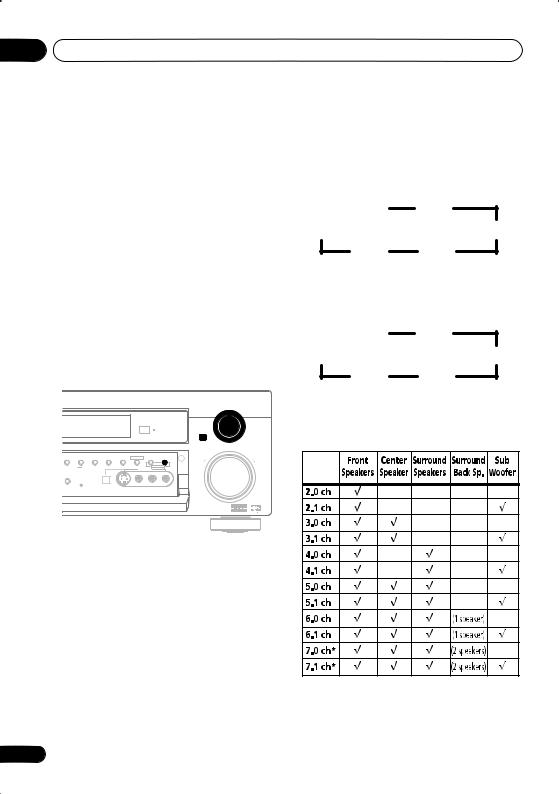
3 Use the MULTI JOG dial to choose your speaker setup.
When a subwoofer was detected in step 2, you can cycle between the following choices:
2.1ch |
3.1ch |
7.1ch* |
4.1ch |
6.1ch |
5.1ch |
* VSX-D812/D912 only
If a subwoofer wasn’t detected in step 2, you can cycle between the following choices:
2.0ch |
3.0ch |
7.0ch* |
4.0ch |
6.0ch |
5.0ch |
*VSX-D812/D912 only
•Check the table below to find the speaker setup that corresponds with your system.
1 If the receiver is off, press STANDBY/ON to turn the power on.
The STANDBY indicator goes out.
2 Press QUICK SETUP.
SW DET flashes in the display while the receiver checks your setup for a subwoofer. SW YES or SW NO confirms the subwoofer check, then the display prompts you to select your speaker setup.
* VSX-D812/D912 only
12
En
5 minute guide
4Press ENTER.
5Use the MULTI JOG dial to choose your room size.
Depending on the distance of your speakers from the listening position, choose between small, medium, or large (S, M or L), M being an average-sized room.
6Press ENTER.
7Use the MULTI JOG dial to choose your listening position.
You can cycle between the following choices:
FWD
MID
BACK
FWD – If you are nearer to the front speakers than the surround speakers
MID – If you are equal distance from the front and surround speakers
BACK – If you are nearer to the surround speakers than the front speakers
8 Press ENTER to confirm your setup.
The display shows the speaker setup, room size and listening position that you have selected.
02
Español Nederlands Deutsch Français Italiano English
13
En

03 Quick surround sound setup
Chapter 3:
Quick surround sound setup
VSX-D912 only
Automatically calibrating your listening area (MCACC)
The Multi-Channel Acoustic Calibration (MCACC) system measures the acoustic characteristics of your listening area, taking into account ambient noise, speaker size and distance, and tests for both channel delay and channel level. After you have set up the microphone provided with your system, the receiver uses the information from a series of test tones to optimize the speaker settings and equalization for your particular room.
RECEIVER
ENTER
MCACC
SETUP
•These test tones can be loud, so take care that there is no one in the room who will be startled by the noise.
•Make sure the mic and speakers are not moved during the MCACC setup.
14
1Connect the microphone to the SETUP MIC jack on the front panel.
2Place the microphone at your normal listening position.
Place the mic about ear level at your normal listening position using the supplied microphone stand on a table or chair.
Make sure there are no obstacles between the speakers and the microphone.
3 If the receiver is off, press STANDBY/ON to turn the power on.
The STANDBY indicator goes out.
4If you have a subwoofer, turn it on.
5Press RECEIVER.
6Press MCACC SETUP.
Try to be as quiet as possible after pressing MCACC SETUP. The system outputs a series of test tones to establish the ambient noise level.
If the noise level is too high, NOISY! blinks in the display for five seconds. To exit and check the noise levels again, press MCACC SETUP (see the notes regarding ambient noise levels below) or press ENTER when you’re prompted to GO NEXT?
The system now checks the microphone and your speaker setup.
If you see an ERR message in the display, there may be a problem with your mic or the speaker connections.
Turn off the power, and check the problem indicated by the ERR message (see below), then try the auto surround setup again.
•ERR MIC – Check the microphone connection.
En

Quick surround sound setup |
03 |
•ERR Fch – Check the front speaker connections.
•ERR Sch – Check the surround or surround back speaker connections.
•ERR SW – Make sure the subwoofer has been switched on and volume on the subwoofer is turned up.
7 Use and to select the speaker system that corresponds to your setup.
Cycle between the following choices:
2.0ch |
2.1ch* |
3.0ch |
3.1ch* |
7.1ch* |
|
|
4.0ch |
7.0ch |
|
|
4.1ch* |
6.1ch* |
6.0ch |
5.1ch* |
5.0ch |
* Indicates a subwoofer is included in your speaker setup
See the table on page 12 if you’re unsure which speaker system to select.
8If you selected a speaker system that includes a subwoofer, press ENTER to check the subwoofer output level.
If the subwoofer output level is too high/low,
SW.VOL.UP/SW.VOL.DWN blinks in the display for five seconds. To exit and check your subwoofer output level, press MCACC SETUP (see the notes regarding noise levels below) or simply turn the subwoofer volume up or down (as indicated), then press ENTER when you’re prompted to GO NEXT?
9Press ENTER to finish the auto surround setup.
The system checks for speaker size, channel delay and channel level. If you have connected a subwoofer, it will check for ambient noise once again.
When the auto surround setup is complete, the volume level returns to normal and COMPLETE, then RESUME shows in the display.
|
|
|
English |
|
• If the room environment is not optimal for |
||||
|
||||
|
the auto surround setup (too much |
|
||
|
ambient noise, echo off the walls, obsta- |
|
||
|
cles blocking the speakers from the |
|
||
|
microphone) the final settings may be |
|
||
|
incorrect. Check for household appli- |
Italiano |
||
|
ances (air conditioner, fridge, fan, etc.), |
|||
|
|
|||
|
that may be affecting the environment |
|
||
|
and switch them off if necessary. |
|
||
• Some older TVs may interfere with the |
|
|||
|
operation of the mic. If this seems to be |
|
||
|
||||
|
happening, switch off the TV when doing |
|
||
|
the auto surround setup. |
Français |
||
• Using the MCACC system to set up your |
||||
|
||||
|
speaker system overwrites any previous |
|
||
|
settings you had for the STANDARD or |
|
||
|
ADVANCED SURROUND modes. |
|
||
• When the STANDARD or ADVANCED |
|
|||
|
SURROUND mode is selected, you can |
Deutsch |
||
|
check the settings made with MCACC by |
|||
|
|
|||
|
using CH SELECT (to check channel |
|
||
|
levels) or by going through the steps in |
|
||
|
Choosing your receiver setup on page 43 |
|
||
|
to check other settings. |
|
||
• Depending on the the characteristics of |
Nederlands |
|||
|
your room, sometimes identical speakers |
|||
|
|
|||
|
with cone sizes of around 12cm will end |
|
||
|
up with different size settings. You can |
|
||
|
correct the setting manually using the |
|
||
|
receiver setup on page 43. |
|
||
|
|
|
Español |
|
15
En

04 Connecting up
Chapter 4:
Connecting up
•Before making or changing any connections, switch off the power and disconnect the power cord from the AC outlet.
Audio/Video cords
Use audio/video cords (not supplied) to connect the audio/video components and a video cord to connect the monitor TV.
Connect red plugs to R (right), white plugs to L (left), and the yellow plugs to VIDEO.
Be sure to insert completely.
R |
L |
|
VIDEO
S-video cables
Use S-video cables (not supplied) to get clearer picture reproduction than regular video cords.
Connect from an S-video jack on the rear of the receiver to an S-video jack on the video component you are hooking up.
Be sure to insert completely.
S VIDEO
16
Component video cords
Use component video cords to get the best possible color reproduction of your video source. The color signal of the TV is divided into the luminance (Y) signal and the color (PB and PR) signals and then output. In this way, interference between the signals is avoided. Connect from the component video jacks on the rear of the receiver to the component video jacks on the video component you are hooking up.
|
Y |
|
|
P |
|
Green |
B |
|
P |
||
Blue |
||
R |
||
|
Red |
Digital audio coaxial cords/ Optical cables
Commercially available digital audio coaxial cords (standard video cords can also be used) or optical cables (not supplied) are used to connect digital components to this receiver.
Be sure to insert completely.
Digital audio coaxial cord |
Optical cable |
(or standard video cord) |
|
En
Connecting up
Connecting digital components
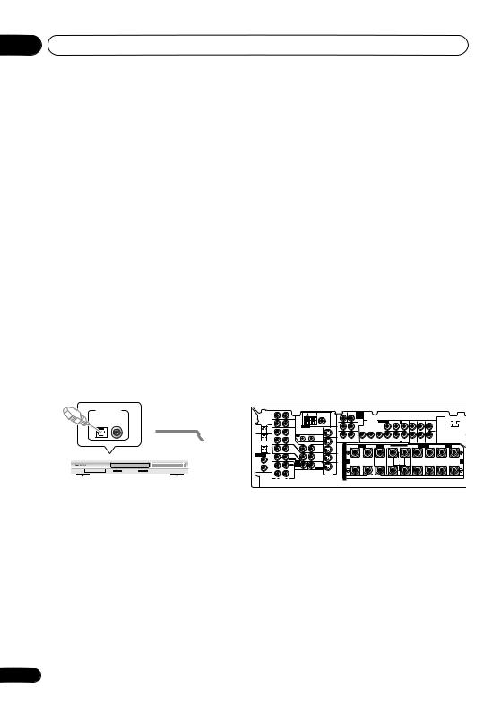
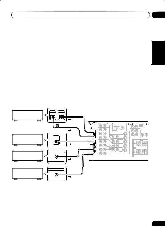
The easiest way to hook up this receiver for surround sound is to use a digital input. You can do this by either coaxial or optical connections (you do not need to do both). The quality of these two types of connections is the same but since some digital components only have one type of digital terminal, it is a matter of matching like with like (for example, the coaxial output from the component to coaxial input on the receiver). The VSX-D712 has three digital inputs on the rear panel (two coaxial inputs and an optical input) and both the VSX-D812 and VSX-D912 have four (two coaxial inputs and two optical inputs). Connect your digital components to the rear panel as shown below.
There is one digital output jack which is marked DIGITAL OUT. If you connect this to the optical input on a digital recorder (currently these include MD, DAT and CD-R) you can make direct digital recordings with this unit.
When connecting your equipment, always make sure the power is turned off and the power cord is disconnected from the AC outlet.
• The arrows indicate the direction of the digital audio signal.
CD recorder |
DIGITAL |
DIGITAL |
OUT |
IN |
This receiver*
|
VSX-D912/D812 only |
|
|
|
|
|
AM |
FM UNBAL |
|
CEN- |
SUB W. |
DVD |
|
|
|
|
|
IN |
|
AUX |
|
TER |
|
|
|||||
|
|
|
|
LOOP |
75 Ω |
|
|
|
|
INPUT |
|
|||
|
|
|
|
|
|
|
|
|
|
|
7.1CH |
|
||
|
|
|
|
|
|
|
|
|
|
|
|
|
|
COMPON |
|
|
DIGITAL |
|
|
|
|
|
|
|
|
|
SURROUND |
VIDEO |
|
|
|
|
|
|
|
|
|
|
|
|
|
|||
|
|
OUT |
OPT |
IN |
|
CD |
ANTENNA |
MONITOR |
R |
|
|
L |
|
MONITOR |
|
|
|
|
|
|
|
|
OUT |
|
|
|
|
|
|
Satellite tuner |
DIGITAL |
|
OPT |
OUT |
|
VCR / |
OUT |
IN |
R |
|
|
L |
|
|
|
2 |
|
|
DVR |
|
|
|
SURROUND BACK |
Y |
PB |
||||
OUT |
(CD-R/TAPE/MD) |
IN |
|
|
|
CONTROL |
OUT |
|||||||
|
|
|
|
|
|
|
|
|
|
|
|
|
|
|
|
|
|
OPT |
|
|
|
VIDEO |
|
VCR/ |
S |
|
R |
FRONT |
L |
|
|
|
1 |
|
|
TV / |
IN |
OUT |
DVR |
|
||||
|
|
|
(TV / |
IN |
|
SAT |
|
|
IN |
P |
|
|
|
|
|
|
|
SAT) |
|
|
IN |
|
|
|
|
|
|
||
|
|
ASSIGNABLE |
COAX |
|
|
DVD |
|
|
E |
|
|
|
|
|
|
|
|
|
|
MONITOR |
T V/ |
|
|
|
|
||||
|
|
DIGITAL |
2 |
|
|
/ LD |
|
|
|
|
|
|||
|
|
|
|
FRONT |
|
OUT |
SAT |
A |
|
|
|
|
||
|
|
IN |
(CD) |
IN |
|
D V D |
|
IN |
A |
|
|
|
||
|
|
|
|
|
|
|
|
|
K |
|
|
|
||
|
|
|
COAX |
|
|
REC |
7.1CH |
SUB |
|
|
|
|
|
|
|
|
|
|
|
INPUT |
DVD / |
|
|
|
|
||||
|
|
|
1 |
|
|
|
IN |
WOOFER |
E |
|
|
|
|
|
|
|
|
OUT |
|
CD-R |
PREOUT |
LD |
|
|
|
|
|||
CD player |
DIGITAL OUT |
|
(DVD |
|
/ TAPE |
|
IN |
|
|
|
|
|||
|
/LD) |
|
|
/ MD |
|
|
R |
|
|
|
|
|||
COAX |
|
|
IN |
|
PLAY |
|
S-VIDEO |
|
|
|
|
|
||
|
|
|
|
|
S |
|
|
|
|
|||||
|
|
|
|
R |
AUDIO |
L |
|
|
|
|
|
|
|
|
DVD player |
DIGITAL OUT |
COAX |
04
Nederlands Deutsch Français Italiano English
* The illustration shows the VSX-D812/D912, but connections for the VSX-D712 are the same.
Español
17
En

04 Connecting up
•If you have an LD player, you need to make special connections to ensure you can play 2 RF format LDs on your system. If this is the case, hook up your DVD or LD player directly to an RF demodulator using both the 2 RF output and either a coaxial or optical digital connection. We also recommend hooking up your digital components to analog audio jacks as well. Make sure the RF demodulator digital in switch is set correctly (optical or coaxial depending on the connection). See the component's instruction manual if you are unsure about its input and output jacks.
Connecting audio components
To begin set up, connect your analog audio components (such as a cassette deck) to the jacks. For components you want to record with, you need to hook up four plugs to the receiver (a set of stereo inputs and a set of stereo outputs), but for components that only play, you only need to hook up one set of stereo plugs. You must also hook up your digital components to analog audio jacks if you want to record to/from digital components (like an MD) to/from analog components. See page 17 for more on digital connections.
When connecting your equipment, always make sure the power is turned off and the power cord is disconnected from the AC outlet.
• The arrows indicate the direction of the audio signal.
CD player
CD-R/Tape/MD deck
|
|
This receiver* |
|
|
|
|
|
|
|
|
|
|
|
|
|
||||||
OUTPUT |
|
|
|
|
|
|
|
|
|
|
|
|
|
|
|
|
|
|
|
|
|
|
L |
|
|
|
|
|
|
AM |
FM UNBAL |
|
CEN- |
SUB W. |
DVD |
|
|
|
|
|
|
|
|
|
|
|
|
|
|
|
|
TER |
|
|
|
|
|
|
|
||||||
|
|
|
|
|
|
|
LOOP |
75 Ω |
|
|
|
|
7.1CH |
|
|
|
|
|
|
|
|
|
|
|
IN |
|
|
AUX |
|
|
|
|
|
|
INPUT |
|
|
|
|
|
|
|
|
|
R |
DIGITAL |
|
|
|
|
|
|
|
|
|
|
|
|
|
COMPONENT |
ASSIGNABLE |
(DVD/LD) IN 1 |
|
|
|
|
|
|
|
|
|
|
|
|
|
|
SURROUND |
|
VIDEO |
|
|
|
|
|
|||
|
OUT |
OPT |
IN |
|
|
CD |
|
|
|
R |
|
MONITOR OUT |
|
|
|
|
|
||||
|
|
|
|
|
ANTENNA |
MONITOR |
OUT |
|
|
L |
|
|
|
|
|
||||||
|
|
|
OPT |
OUT |
|
|
VCR / |
OUT |
IN |
|
R |
|
|
L |
|
|
|
|
|
|
|
|
|
|
2 |
|
|
|
DVR |
|
|
|
SURROUND BACK |
|
|
|
|
|
|
|
|
||
|
|
|
|
|
|
|
|
|
CONTROL |
|
Y |
|
PB |
PR |
Y |
PB |
PR |
|
|||
|
|
(CD-R/TAPE/MD) |
IN |
|
|
|
VIDEO |
|
OUT |
|
|
|
|
|
|
|
|
(TV/SAT) IN 2 |
|
|
|
|
|
|
OPT |
|
|
|
|
|
VCR/ |
S |
|
R |
FRONT |
L |
CENTER |
R SURROUND BACK |
L |
||||
|
|
|
1 |
|
|
|
TV / |
IN |
OUT |
DVR |
|
||||||||||
|
|
|
(TV / |
IN |
|
|
SAT |
|
|
IN |
P |
|
|
|
|
|
|
|
|
|
|
REC |
PLAY |
|
SAT) |
|
|
|
IN |
|
|
|
|
|
|
|
|
|
|
|
|
||
ASSIGNABLE |
COAX |
|
|
|
DVD |
|
|
E |
|
|
|
|
|
|
|
|
|
|
|||
|
|
|
|
MONITOR |
TV / |
|
|
|
|
|
|
|
|
|
|
||||||
|
|
DIGITAL |
2 |
|
|
|
/ LD |
|
|
|
|
|
|
|
|
|
|
|
|||
|
|
|
|
|
FRONT |
|
OUT |
SAT |
A |
|
|
|
|
|
|
|
|
|
|
||
|
|
IN |
(CD) |
IN |
|
|
D V D |
|
IN |
A |
|
|
|
|
|
|
SINGLE |
|
|
||
|
|
|
|
|
|
|
|
|
|
K |
|
|
|
|
|
|
SEEINSTRUCTION |
|
|
||
|
|
|
COAX |
|
|
|
REC |
7.1CH |
SUB |
|
|
|
|
|
|
|
|
MANUAL |
|
|
|
|
|
|
|
|
|
INPUT |
DVD / |
|
|
|
|
|
|
|
|
|
|
||||
|
|
|
1 |
|
|
|
|
IN |
WOOFER |
E |
|
|
|
|
|
|
|
|
|
|
|
|
|
|
OUT |
|
|
CD-R |
PREOUT |
LD |
|
|
|
|
|
|
|
|
|
|
|||
|
|
|
(DVD |
|
/ |
TAPE |
|
IN |
|
|
|
|
|
|
|
|
|
|
|||
|
|
|
/LD) |
|
|
|
/ MD |
|
|
R |
|
|
|
|
|
|
|
|
|
|
|
|
|
|
|
|
|
|
S-VIDEO |
|
|
|
|
|
|
|
|
|
|
|
|||
|
|
|
|
IN |
|
|
PLAY |
|
|
S |
|
|
|
|
|
|
|
|
|
|
|
|
|
|
|
AUDIO |
|
|
|
|
|
|
|
|
|
|
|
|
|
|
|||
|
|
|
|
R |
L |
|
|
|
|
|
|
|
|
|
|
|
|
|
|
|
|
* The illustration shows the VSX-D812/D912, but connections for the VSX-D712 are the same.
18
En

Connecting up
Connecting DVD multi-channel components
If you prefer to use a seperate component for decoding DVDs, you can connect a decoder or a DVD player with multi-channel analog outputs to the multi-channel inputs of this receiver.
When connecting your equipment, always make sure the power is turned off and the power cord is disconnected from the AC outlet.
• The arrows indicate the direction of the signal.
DIGITAL |
|
|
|
|
|
OUT |
|
|
|
|
|
(CD-R/TAPE/MD) |
|
|
|
|
|
ASSIGNABLE |
|
|
|
|
|
DIGITAL |
|
|
|
|
|
IN |
|
|
|
|
|
(DVD |
OUT |
|
/ |
TAPE |
PREOUT |
/LD) |
|
|
|
/ MD |
IN |
|
IN |
|
|
PLAY |
S-VIDEO |
|
|
|
|
||
|
R |
AUDIO |
L |
|
|
This receiver*
 VSX-D812/D912 only
R |
S |
VIDEO
OUTPUT
DVD/multi-channel decoder with multi-channel analog output jacks
* The illustration shows the VSX-D812/D912, but connections for the VSX-D712 are the same.
•The multi-channel input can only be used when DVD 5.1 ch (VSX-D712) or DVD 7.1 ch (VSXD812/D912) is selected (see page 42).
VSX-D812/D-912 only
•If the component you are connecting only has one surround back channel output, change the Surround back channel input setting (page 49) to SB 1ch IN.
04
Español Nederlands Deutsch Français Italiano English
19
En

04 Connecting up
Connecting video components
Connect your video components to the jacks as shown below. With digital video components (like a DVD player), you must use the connections shown on this page for the video signal, but in order to hear a digital source (like a DVD) you should hook up the audio to a digital input (see page 17). It is also a good idea to hook up your digital components with analog audio connections (see page 18).
For better quality video, you can hook up using the component video jacks or the S-video jacks (quality descends in this order) on the rear of the receiver instead of the regular video jacks. Make sure they are connected to the video component using the same kind of connection.
When connecting your equipment, always make sure the power is turned off and the power cord is disconnected from the AC outlet.
• The arrows indicate the direction of the signal
|
|
|
|
|
|
|
|
|
|
|
|
|
|
Video deck |
|
|
|
|
||
|
|
|
|
|
|
|
|
|
|
|
|
|
|
INPUT |
|
OUTPUT |
|
|
|
|
|
|
This receiver* |
|
|
|
|
|
|
VIDEO |
VIDEO |
|
|
|
|||||||
|
OUTPUT |
|
|
|
|
|
|
|
|
|
|
|
|
L |
|
L |
|
|
|
|
|
|
|
|
|
|
|
AM |
FM UNBAL |
|
CEN- |
SUB WOOFER |
|
|
|
|
|
|
|
|
|
TV tuner |
VIDEO |
|
|
|
|
AUX |
|
TER |
|
|
|
|
|
|
|
|
||||
|
|
|
|
LOOP |
75 Ω |
|
|
|
|
|
R |
|
R |
|
|
|
|
|||
|
|
|
IN |
|
|
|
|
|
|
|
|
|
|
L |
|
L |
PREOUT |
|||
(or Satellite tuner) |
L |
DIGITAL |
|
|
|
|
|
|
|
|
|
|
|
|
|
|
|
SURROUND |
||
|
|
|
|
|
|
|
|
SURROUND |
|
|
|
|
|
|
|
BACK |
||||
OUT |
OPT |
IN |
|
CD |
ANTENNA |
MONITOR |
R |
|
L |
|
|
|
|
|
|
|
|
|
||
|
R |
|
|
|
|
|
|
OUT |
|
|
|
|
|
|
|
|
|
|
|
|
|
|
|
|
|
|
|
|
|
|
SURROUND |
|
|
|
|
|
|
|
|
||
|
|
OPT |
OUT |
|
VCR / |
OUT |
IN |
R |
|
L |
BACK |
|
|
|
|
|
|
|
|
|
|
|
|
2 |
|
|
DVR |
|
|
|
|
|
|
|
|
|
|
R |
|
R |
|
|
|
|
|
|
|
|
|
CONTROL |
|
DVD 7.1CH INPUT |
|
|
|
|
|
|
CENTER |
|||
|
|
(CD-R/TAPE/MD) |
IN |
|
|
|
OUT |
|
|
|
|
|
|
|
FRONT |
|
SURROUND |
|||
|
|
|
OPT |
|
|
|
VIDEO |
|
VCR/ |
S |
R |
FRONT |
L |
CENTER |
R SURROUND BACK |
L |
R |
SURROUND L |
||
|
|
|
1 |
|
|
TV / |
IN |
OUT |
DVR |
|||||||||||
|
|
|
(TV / |
|
|
SAT |
|
|
IN |
P |
|
|
|
|
|
|
|
|
|
|
|
|
|
SAT) IN |
|
|
IN |
|
|
|
|
|
|
|
|
|
|
|
|
||
|
|
ASSIGNABLE |
COAX |
|
|
DVD |
|
|
E |
|
|
|
|
|
|
|
|
|
|
|
|
|
|
|
|
MONITOR |
TV / |
|
|
|
|
|
|
|
|
|
|
||||
|
|
DIGITAL |
2 |
|
|
/ LD |
|
|
|
|
|
|
|
|
|
|
|
|||
|
|
|
|
FRONT |
|
OUT |
SAT |
A |
|
|
|
|
|
|
|
|
|
|
||
|
|
IN |
(CD) |
IN |
|
D V D |
IN |
A |
|
INPUT |
|
|
SINGLE |
|
|
|
|
|||
|
|
|
|
|
|
|
|
|
K |
|
|
|
SEEINSTRUCTION |
|
|
|
|
|||
|
|
|
COAX |
|
|
REC |
7.1CH |
SUB |
|
|
|
|
|
MANUAL |
|
|
|
|
||
|
|
|
|
|
INPUT |
DVD / |
|
|
|
|
|
|
|
|
|
|
||||
|
OUTPUT |
|
1 |
|
|
|
IN |
WOOFER |
E |
|
|
|
|
|
|
|
|
|
|
|
|
|
OUT |
|
CD-R |
PREOUT |
LD |
|
|
|
|
|
|
|
|
|
|
||||
|
|
(DVD |
|
|
|
|
|
|
|
|
|
|
|
|||||||
|
|
|
|
|
/ TAPE |
|
|
IN |
R |
|
|
|
|
|
|
|
|
|
|
|
DVD or LD player |
VIDEO |
|
/LD) |
IN |
|
/ MD |
|
S-VIDEO |
|
|
|
|
|
|
|
|
|
|
||
|
|
|
PLAY |
|
|
S |
|
|
VIDEO |
|
|
|
|
|
|
|
||||
|
|
|
R |
AUDIO |
L |
|
|
|
|
|
|
|
|
|
|
|
|
|||
|
L |
|
|
|
|
|
|
|
|
|
|
|
|
|
|
|
|
|
|
|
|
R |
|
|
|
|
|
|
|
|
|
|
|
|
|
TV (monitor) |
|
||||
|
|
|
|
|
|
|
|
|
|
|
|
|
|
|
|
|||||
* The illustration shows the VSX-D812/D912, but connections for the VSX-D712 are the same.
Connecting to the front panel video |
EO/ |
SIGNAL |
MIDNIGHT/ |
SB CH |
TONE |
QUICK |
terminal |
CT |
SELECT |
LOUDNESS SPEAKERS |
MODE |
SETUP |
|
|
|
|
|
MULTI JOG |
||
Front video connections are accessed via the |
|
|
|
VIDEO INPUT |
|
|
|
|
|
|
|
|
|
front panel using the VIDEO button. There are |
SETUP |
DIGITAL IN |
|
|
|
|
|
MIC |
VIDEO |
L |
AUDIO R |
||
|
|
|
S-VIDEO |
|||
standard audio/video jacks as well as an |
|
|
|
|
|
|
S-video jack (the VSX-D912 also has an optical |
|
|
|
|
|
|
input). Hook them up the same way you made |
|
|
|
|
|
|
the rear panel connections. |
|
|
|
|
|
|
|
|
|
|
V |
L |
R |
|
|
DIGITAL OUT |
VIDEO OUTPUT |
|||
Video
camera
(etc.)
20
En
Connecting up
Connecting antennas
Connect the AM loop antenna and the FM wire antenna as shown below. To improve reception and sound quality, connect external antennas (see Using external antennas below). Always make sure that the receiver is switched off and unplugged from the wall outlet before making or changing any connections.
|
AM loop |
|
|
|
|
|
|
|
|||
|
antenna |
|
|
|
|
|
|
|
|||
|
|
|
|
|
|
|
|
FM wire |
|
||
|
|
|
|
|
|
75 Ω |
|
antenna |
|
||
|
|
|
|
|
AM |
FM UNBAL |
|
CEN- |
SUB WOOFER |
|
|
|
|
|
|
|
|
TER |
|
||||
|
|
|
|
AUX |
LOOP |
|
|
|
|
|
|
|
|
IN |
|
|
|
|
|
|
|
|
|
DIGITAL |
|
|
|
|
|
|
|
|
SURROUND |
|
|
OUT |
OPT |
IN |
|
CD |
ANTENNA |
MONITOR |
R |
|
L |
|
|
|
|
|
|
|
|
OUT |
|
|
|
|
|
|
|
|
|
|
|
|
|
|
SURROUND |
|
|
|
OPT |
OUT |
|
VCR / |
OUT |
IN |
R |
|
L |
BACK |
|
|
2 |
|
|
DVR |
|
|
|
|
|
|
|
(CD-R/TAPE/MD) |
IN |
|
|
|
CONTROL |
OUT |
DVD 7.1CH INPUT |
|
|
||
|
|
VIDEO |
|
|
|
|
|
||||
|
OPT |
|
|
|
|
VCR/ |
S |
R |
FRONT |
L |
|
|
1 |
|
|
TV / |
IN |
OUT |
DVR |
||||
|
(TV / |
IN |
|
SAT |
|
|
IN |
P |
|
|
|
|
SAT) |
|
|
IN |
|
|
|
|
|
||
ASSIGNABLE |
COAX |
|
|
DVD |
|
|
E |
|
|
|
|
|
|
|
MONITOR |
T V / |
|
|
|
||||
DIGITAL |
2 |
|
|
/ LD |
|
|
|
|
|||
|
|
FRONT |
|
OUT |
SAT |
A A |
|
|
|
||
IN |
(CD) |
IN |
|
|
IN |
|
|
|
|||
|
|
D V D |
|
|
|
|
|||||
|
COAX |
|
|
REC |
7.1CH |
SUB |
|
K |
|
|
|
|
|
|
INPUT |
DVD / |
|
|
|
||||
|
1 |
|
|
|
IN |
WOOFER |
E |
|
|
|
|
|
OUT |
|
CD-R |
PREOUT |
LD |
|
|
|
|||
|
(DVD |
|
/ TAPE |
|
IN |
|
|
|
|||
|
/LD) |
|
|
/ MD |
|
S-VIDEO |
R |
|
|
|
|
|
|
IN |
AUDIO |
PLAY |
|
|
|
S |
|
|
|
|
|
R |
L |
|
|
|
|
|
|
|
|
FM wire antenna
Connect the FM wire antenna and fully extend vertically along a window frame or another suitable place that gives good reception.
AM loop antenna
Assemble the antenna and connect to the receiver. Attach (if necessary) and face in the direction that gives the best reception.
Antenna snap connectors
Twist the exposed wire strands together and insert into the hole, then snap the connector shut.
10mm
Using external antennas
To improve FM reception
Connect an external FM antenna.
One-touch |
75Ω coaxial |
|
PAL connector |
cable |
|
AM |
FM UNBAL |
|
LOOP |
75 Ω |
|
ANTENNA
To improve AM reception
Connect a 5–6 metre length of vinyl-coated wire to the AM antenna terminal without disconnecting the supplied AM loop antenna.
For the best possible reception, suspend horizontally outdoors.
Outdoor antenna
5–6m
Indoor antenna (vinyl-coated wire)
AM |
FM UNBAL |
LOOP |
75 Ω |
ANTENNA
04
Español Nederlands Deutsch Français Italiano English
21
En

04 Connecting up
Connecting the speakers (VSX-D712)
A complete setup of six speakers (including the subwoofer) is shown below, but everyone’s home setup will vary. Simply connect the speakers you have in the manner shown below. The receiver will work with just two stereo speakers (the front speakers in the diagram) but using at least three speakers is recommended, and a complete setup is best. If you’re not using a subwoofer, change the front speaker setting (see Speaker setting on page 44) to large.
Make sure you connect the speaker on the right to the right terminal and the speaker on the left to the left terminal. Also make sure the positive and negative (+/–) terminals on the receiver match those on the speakers.
Be sure to complete all connections before connecting this unit to the AC power source.
• Use speakers with a nominal impedance of 8 Ω to 16 Ω.
Front speakers |
Center speaker |
Surround speakers |
||
L |
R |
C |
LS |
RS |
AM |
FM UNBAL |
|
LOOP |
COMPONENT |
|
|
1 |
|
|
VIDEO |
|
OUT |
MONITOR OUT |
|
|
|
|
|
|
|
|
|
MONITOR |
OUT |
|
|
|
|
|
|
|
|
|
|
|
|
|
|
|
|
|
|
|
|
SURROUND |
|
|
|
|
|
|
|
|
|
|
|
|
|
OUT |
|
VCR / |
OUT |
IN |
|
DVD 5.1CH INPUT |
|
|
|
|
|
|
|
|
|
|
|
|
|
|
|
|
|
|
|
|
|
|
|
|
|
|
|
||||
|
|
|
|
DVR |
|
|
|
|
|
Y |
PB |
PR |
Y |
PB |
PR |
|
|
|
|
|
|
|
|
|
|
CONTROL |
|
|
|
|
|
|
|
||||||
|
|
IN |
|
|
|
OUT |
|
|
|
|
|
|
(TV/SAT) IN 2 |
|
|
|
|
|
|
|
OPT |
|
|
|
IN |
VIDEO |
VCR/ |
S |
R |
FRONT |
L |
CENTER |
|
R |
SURROUND |
L |
R |
FRONT |
L |
|
1 |
|
|
TV / |
OUT |
DVR |
|
||||||||||||
|
(TV / |
IN |
|
SAT |
|
|
IN |
P |
|
|
|
|
|
|
|
|
|
|
|
|
SAT) |
|
|
IN |
|
|
|
|
|
|
|
|
|
|
|
|
|
||
ASSIGNABLE |
COAX |
|
|
DVD |
|
|
E |
|
|
|
|
|
|
|
|
|
|
|
|
|
|
|
MONITOR |
T V / |
|
|
|
|
|
|
|
|
|
|
|
||||
DIGITAL |
2 |
|
|
/ LD |
|
|
|
|
|
|
|
|
|
|
|
|
|
||
|
|
FRONT |
|
OUT |
SAT |
A |
|
|
|
|
|
|
|
|
|
|
|
||
IN |
(CD) |
IN |
|
|
IN |
A |
|
|
|
|
|
|
|
|
|
B |
|||
|
|
D V D |
|
|
|
|
|
|
|
|
|
|
|||||||
|
COAX |
|
|
REC |
5.1CH |
SUB |
|
K |
|
|
|
|
|
|
|
|
|
|
|
|
|
|
INPUT |
WOOFER |
DVD / |
E |
|
|
|
|
|
|
|
|
|
|
|
||
|
1 |
|
|
|
IN |
|
|
|
|
|
|
|
|
|
|
|
|||
|
(DVD |
OUT |
|
CD-R |
PREOUT |
LD |
|
|
|
|
|
|
|
|
|
|
|
||
|
|
/ TAPE |
|
IN |
R |
|
|
|
|
|
|
|
|
|
|
|
|||
|
/LD) |
|
|
/ MD |
|
SURROUND |
|
|
|
|
|
|
|
|
|
|
|
||
|
|
|
|
|
|
BACK |
|
|
|
|
|
|
|
|
|
|
|
|
|
|
|
IN |
AUDIO |
PLAY |
|
S-VIDEO |
|
S |
|
|
|
|
|
|
|
|
|
|
|
|
|
R |
L |
|
|
|
|
|
|
|
|
|
|
|
|
|
|
|
|
VSX-D712
Powered subwoofer
SW
22
En
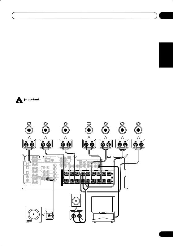
Connecting up
Connecting the speakers (VSX-D812/D912)
A complete setup of eight speakers (including the subwoofer) is shown below, but everyone’s home setup will vary. Simply connect the speakers you have in the manner shown below. The receiver will work with just two stereo speakers (the front speakers in the diagram) but using at least three speakers is recommended, and a complete setup is best for surround sound. If you’re not using a subwoofer, change the front speaker setting (see Speaker setting on page 44) to large.
Make sure you connect the speaker on the right to the right terminal and the speaker on the left to the left terminal. Also make sure the positive and negative (+/–) terminals on the receiver match those on the speakers.
Be sure to complete all connections before connecting this unit to the AC power source.
• Use speakers with a nominal impedance of 8 Ω to 16 Ω.
Front speakers |
Center speaker |
Surround speakers |
Surround back speakers |
|||||||||||
L |
|
R |
|
C |
LS |
|
RS |
|
SBL |
SBR |
||||
|
|
|
|
|
|
|
|
|
|
|
|
|
|
|
|
|
|
|
|
|
AM |
FM UNBAL |
|
CEN- |
SUB W. |
|
DVD |
|
|
|
|
|
|
|
|
|
|
|
|
|
|
|
|
|
|
|
|
|
TER |
|
|
|
|
|
|
|
|
|
|
|
|
|
|
|
||||
|
|
|
|
|
|
LOOP |
75 Ω |
|
|
|
|
|
7.1CH |
|
|
|
|
|
|
|
|
|
|
|
|
|
|
|
IN |
|
|
AUX |
|
|
|
|
|
|
|
INPUT |
|
|
|
|
|
|
|
|
|
|
|
|
|
|
|
|
|
|
|
|
|
|
|
|
|
|
|
COMPONENT |
ASSIGNABLE |
(DVD/LD) IN 1 |
|
|
L |
L |
SURROUND |
|
|
|
||
DIGITAL |
|
|
|
|
|
|
|
|
|
|
|
|
|
VIDEO |
|
|
|
|
|
|
||||||
|
|
|
|
|
|
|
|
|
|
|
SURROUND |
|
|
|
|
|
|
|
|
|
BACK |
|
|
|
||
OUT |
OPT |
IN |
|
|
CD |
|
|
|
|
|
|
MONITOR OUT |
|
|
|
|
|
|
|
|
|
|
|
|||
|
|
|
|
ANTENNA |
MONITOR |
OUT |
R |
|
|
|
L |
|
|
|
|
|
|
|
|
|
|
|
||||
|
OPT |
OUT |
|
|
VCR / |
OUT |
IN |
|
R |
|
|
|
L |
|
|
|
|
|
|
|
|
|
|
|
|
|
|
2 |
|
|
|
DVR |
|
|
|
SURROUND BACK |
|
|
|
|
|
|
|
|
|
|
|
|
|
|
|
||
|
|
|
|
|
|
|
CONTROL |
|
|
Y |
PB |
|
PR |
Y |
PB |
PR |
|
R |
R |
|
|
|
|
|||
(CD-R/TAPE/MD) |
IN |
|
|
|
VIDEO |
|
OUT |
|
|
|
|
|
|
|
|
|
(TV/SAT) IN 2 |
|
|
FRONT |
SURROUND |
CENTER |
|
|
|
|
|
OPT |
|
|
|
|
|
VCR/ |
S |
|
|
R |
FRONT |
L |
CENTER |
R SURROUND BACK |
L |
R |
SURROUND |
L |
R |
FRONT |
L |
||||
|
1 |
|
|
|
TV / |
IN |
OUT |
DVR |
|
|
||||||||||||||||
|
(TV / |
IN |
|
|
SAT |
|
|
IN |
P |
|
|
|
|
|
|
|
|
|
|
|
|
|
|
|
|
|
|
SAT) |
|
|
|
IN |
|
|
|
|
|
|
|
|
|
|
|
|
|
|
|
|
|
|
|
||
ASSIGNABLE |
COAX |
|
|
|
DVD |
|
|
E |
|
|
|
|
|
|
|
|
|
|
|
|
|
|
|
|
|
|
|
|
|
|
MONITOR |
T V / |
|
|
|
|
|
|
|
|
|
|
|
|
|
|
|
|
|
||||
DIGITAL |
2 |
|
|
|
/ LD |
|
OUT |
SAT |
A |
|
|
|
|
|
|
|
|
|
|
|
|
|
|
|
|
|
IN |
(CD) |
IN |
|
|
FRONT |
D V D |
IN |
A |
|
|
|
|
|
|
|
SINGLE |
|
|
|
|
|
|
|
B |
||
|
|
|
|
|
|
|
|
K |
|
|
|
|
|
|
|
SEEINSTRUCTION |
|
|
|
|
|
|
|
|||
|
COAX |
|
|
|
REC |
7.1CH |
SUB |
DVD / |
|
|
|
|
|
|
|
|
MANUAL |
|
|
|
|
|
|
|
|
|
|
1 |
|
|
|
INPUT |
WOOFER |
E |
|
|
|
|
|
|
|
|
|
|
|
|
|
|
|
|
|
||
|
OUT |
|
|
CD-R |
IN |
PREOUT |
LD |
|
|
|
|
|
|
|
|
|
|
|
|
|
|
|
|
|
||
|
(DVD |
|
/ |
TAPE |
|
IN |
R |
|
|
|
|
|
|
|
|
|
|
|
|
|
|
|
|
|
||
|
/LD) |
|
|
|
/ MD |
|
S-VIDEO |
|
|
|
|
|
|
|
|
|
|
|
|
|
|
|
|
|
||
|
|
IN |
|
|
PLAY |
|
|
S |
|
|
|
|
|
|
|
|
|
|
|
|
|
|
|
|
|
|
|
|
AUDIO |
|
|
|
|
|
|
|
|
|
|
|
|
|
|
|
|
|
|
|
|
|
|||
|
|
R |
L |
|
|
|
|
|
|
|
|
|
|
|
|
|
|
|
|
|
|
|
|
|
|
|
VSX-D812/D912
|
Passive |
|
|
Powered subwoofer |
subwoofer |
|
|
or single |
TV |
||
SW |
|||
surround |
|||
|
|||
|
back |
|
|
INPUT |
speaker |
|
04
Español Nederlands Deutsch Français Italiano English
23
En

04 Connecting up
•When using the speaker on your TV as the center speaker (C), connect the CENTER PREOUT jack on this unit to the audio input jack on your TV. In this case the center speaker shown is unnecessary.
•If you are using only one surround back speaker, connect the positive wire to the right channel (+) terminal, and the negative wire to the left channel (–) terminal (see illustration on page 11).
•If you select subwoofer (SB SW) in the
Surround back speaker setting on page 45 you can hook up a subwoofer instead of speakers to the surround back speaker terminals. Connect the positive wire to the right channel (+) terminal, and the negative wire to the left channel (–) terminal (see illustration on page 11).
Speaker terminals
1 |
2 |
3 |
10mm
1Twist exposed wire strands together.
2Loosen speaker terminal and insert exposed wire.
Make sure that all the bare speaker wire is twisted together and inserted fully into the speaker terminal. If any of the bare speaker wire is touching the back panel when you switch the unit on, the power may cut off as a safety measure. Use good quality speaker wire to connect the speakers to the receiver.
3Tighten terminal.
24
•These speaker terminals are hazardous when live. To prevent the risk of electric shock when connecting or disconnecting the speaker cables, disconnect the power cord.
A and B speaker systems
The receiver has two speaker systems: A and B. A is the main system supporting the full speaker setup. If you switch on both A and B speaker systems, only the front speakers and the (active) subwoofer will be audible. No sound will come from the center, surround, or surround back speakers, but multi-channel sources will be down-mixed to the active speakers so no sound will be lost. Similarly, if you choose just the B system you‘ll only hear the front speakers connected to the B system and multi channel sources will be downmixed to these two speakers.
• Press the SPEAKERS button on the front panel to switch between speaker systems (A, B or both).
Hints on speaker placement
Speakers are usually designed with a particular placement in mind. Some are designed to be floorstanding, while others should be placed on stands to sound their best. Some should be placed near a wall; others should be placed away from walls. We have provided a few tips on getting the best sound from your speakers (following), but you should also follow the guidelines on placement that the speaker manufacturer provided with your particular speakers to get the most out of them.
•Place the front left and right speakers at equal distances from the TV.
En

Connecting up
•When placing speakers near the TV, we recommend using magnetically shielded speakers to prevent possible interference, such as discoloration of the picture when the TV is switched on. If you do not have magnetically shielded speakers and notice discoloration of the TV picture, move the speakers farther away from the TV.
•Place the center speaker above or below the TV so that the sound of the center channel is localized at the TV screen.
•If possible, place the surround speakers slightly above ear level.
•Try not to place the surround speakers further away from the listening position than the front and center speakers. Doing so can weaken the surround sound effect.
•To achieve the best possible surround sound, install your speakers as shown below. Be sure all speakers are installed securely to prevent accidents and improve sound quality.
•If you choose to install the center speaker on top of the TV, be sure to secure it with putty, or by other suitable means, to reduce the risk of damage or injury resulting from the speaker falling from the TV in the event of external shocks such as earthquakes.
Overhead view of speaker setup
Front |
|
Front |
Left |
Center |
Right |
|
|
Subwoofer |
Surround |
|
Surround |
Left |
|
Right |
|
Listening Position |
|
Surround Back Left |
Surround Back Right |
|
Single Surround Back Speaker
3-D view of 6.1 channel speaker setup
3-D view of 7.1 channel speaker setup
04
Español Nederlands Deutsch Français Italiano English
25
En
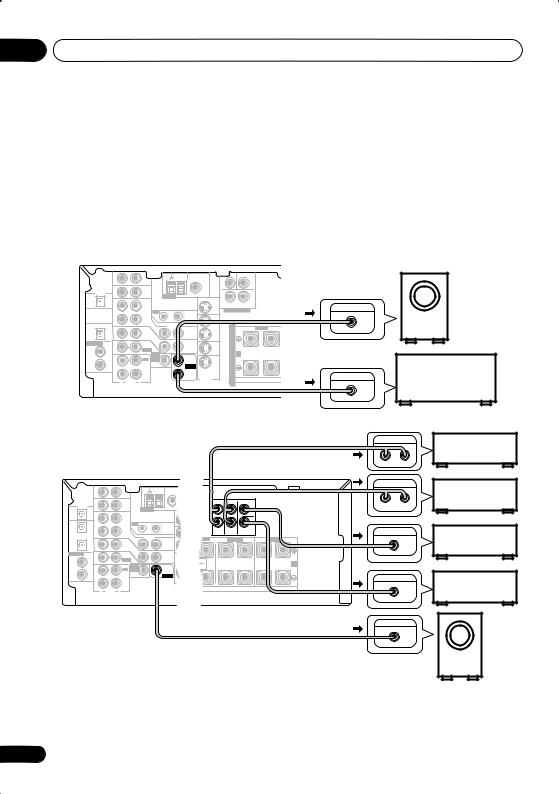
04 Connecting up
Connecting additional amplifiers
This receiver has more than sufficient power for any home use, however it is possible to add additional amplifiers to every channel on the VSX-D812/D912 or the surround back channel of the VSX-D712. Make the connections shown below to add amplifiers to power your speakers. Always make sure that the receiver is switched off and unplugged from the wall outlet before making or changing any connections.
• The arrows indicate the direction of the audio signal.
VSX-D712 |
|
|
|
|
|
|
|
|
|
|
|
|
|
|
|
|||
|
|
|
|
|
AM |
FM UNBAL |
|
TERCEN- |
SUB WOOFER |
|
|
|
|
|
|
|
|
|
|
|
|
|
AUX |
LOOP |
75 Ω |
|
|
|
|
|
|
|
|
|
|
|
Powered |
|
|
IN |
|
|
|
|
|
|
|
|
|
|
|
|
|
|
||
DIGITAL |
|
|
|
|
|
|
|
|
|
|
|
|
|
|
|
|
|
|
OUT |
OPT |
IN |
|
CD |
ANTENNA |
MONITOR |
OUT |
R |
L |
|
|
|
|
|
|
|
|
subwoofer |
|
|
|
|
|
|
|
|
|
|
|
|
|
|
|
|
|||
|
|
|
|
|
|
|
|
SURROUND |
|
|
|
|
INPUT |
|
|
|
||
|
|
OUT |
|
VCR / |
|
|
|
DVD 5.1CH INPUT |
|
|
|
|
|
|
|
|||
|
|
|
OUT |
IN |
|
|
|
|
|
|
|
|
|
|
|
|
||
|
|
|
|
DVR |
|
|
|
|
|
|
|
|
|
|
|
|
|
|
|
|
IN |
|
|
|
CONTROL |
OUT |
|
|
|
|
|
|
|
|
|
|
|
|
OPT |
|
|
VIDEO |
|
|
|
|
|
|
|
|
|
|
|
|
||
|
|
|
|
|
VCR/ |
S |
R |
FRONT |
L |
CENTER |
R |
SURROUND |
L |
R |
FRONT |
L |
||
|
1 |
|
|
TV / |
IN |
OUT |
DVR |
|
|
|
|
|||||||
|
(TV / |
|
|
|
IN |
|
|
|
|
|
|
|
|
|
|
|
||
|
|
|
SAT |
|
|
P |
|
|
|
|
|
|
|
|
|
|
||
|
SAT) IN |
|
|
IN |
|
|
|
|
|
|
|
|
|
|
|
|
||
ASSIGNABLE |
COAX |
|
|
DVD |
|
|
E |
|
|
|
|
|
|
|
|
|
|
|
DIGITAL |
2 |
|
|
/ LD |
|
MONITOR |
T V/ |
|
|
|
|
|
|
|
|
|
|
|
|
|
FRONT |
|
OUT |
SAT |
A |
|
|
|
|
|
|
|
|
|
|
||
IN |
(CD) |
IN |
|
|
|
IN |
A |
|
|
|
|
|
|
|
|
B |
||
|
|
D V D |
|
|
|
|
|
|
|
|
|
|||||||
|
COAX |
|
|
REC |
5.1CH |
SUB |
|
K |
|
|
|
|
|
|
|
|
|
Surround back |
|
OUT |
|
INPUT |
PREOUT |
DVD / |
|
|
|
|
|
|
|
|
|
|
|||
|
(DVD |
|
/ TAPE |
|
|
|
|
|
|
|
|
|
|
|
||||
|
1 |
|
|
|
IN |
WOOFER |
E |
|
|
|
|
|
|
|
|
|
|
|
|
|
|
CD-R |
|
LD |
|
|
|
|
|
|
|
|
|
|
|||
|
/LD) |
IN |
|
/ MD |
SURROUND |
IN |
S |
|
|
|
|
|
ANALOG IN |
|
|
channel amplifier |
||
|
|
|
PLAY |
|
S-VIDEO |
|
|
|
|
|
|
|
|
|||||
|
|
|
|
|
|
BACK |
|
R |
|
|
|
|
|
|
|
|
|
|
|
|
R |
AUDIO |
L |
|
|
|
|
|
|
|
|
|
|
|
|
|
or powered speaker |
|
|
|
|
|
|
|
|
|
|
|
|
|
|
|
|
|
|
|
VSX-D812/D912 |
|
|
|
|
|
|
|
|
|
|
|
|||||||||
|
|
|
|
|
OPT |
|
|
OPT |
AM |
|
FM |
|
|
|
|
|
|
|
|
|
|
|
|
|
|
AUX |
|
|
LOOP |
75 Ω |
|
|
|
|
|
|
|
|
|||
|
|
IN |
|
|
|
|
|
|
|
|
|
|
|
|
|
|
|
|
||
|
|
|
|
|
|
|
|
|
COMPONENT |
|
|
L |
L |
|
SURROUND |
|
|
|
||
DIGITAL |
|
|
|
|
|
|
|
|
VIDEO |
|
ASSIGNABLESSIG |
|
|
|
|
|
||||
|
|
( TV / |
¥ |
(CD-R/ |
ø |
1 |
|
2 |
COMPONENT |
|
|
|
|
BACK |
|
|
|
|||
OUT |
|
|
|
|
VIDEO |
|
|
|
|
|
|
|
|
|||||||
|
OPT |
IN |
SAT) |
|
/ TAPECD |
|
|
DIGITALANTENNAOUT |
|
|
|
|
|
|
|
|
|
|
|
|
|
|
|
|
|
/ MD) |
|
|
|
MONITOR |
OUT |
|
|
|
|
|
|
|
|
||
|
OPT |
OUT |
|
|
VCR / |
OUT |
|
|
IN |
|
|
|
|
|
|
|
|
|
||
|
2 |
|
|
|
DVR |
|
Y |
PPBB |
|
PPRR |
|
R |
R |
|
|
|
|
|
||
|
|
|
|
|
|
|
|
|
|
|
|
|
|
|
||||||
(CD-R/TAPE/MD) |
IN |
|
|
|
|
|
|
|
|
CONTROL |
|
FRONT |
SURROUND |
CENTER |
|
|
|
|||
|
|
|
|
|
FRONT |
VIDEO |
|
CENTER |
|
|
|
|
|
|
|
|
||||
|
OPT |
|
S |
|
R |
|
|
|
|
SURROUND |
|
|
FRONT |
|
||||||
|
1 |
|
|
|
L |
|
L |
R |
L |
R |
L |
|||||||||
|
|
TV / |
|
IN |
|
|
OUT |
|
|
|
||||||||||
|
(TV / |
|
P |
|
|
|
|
|
|
|
|
|
|
|
|
|||||
|
IN |
SAT |
|
|
|
|
|
|
|
|
|
|
|
|
|
|
||||
|
SAT) |
|
|
|
IN |
|
|
|
|
|
|
|
|
|
|
|
|
|||
ASSIGNABLE |
COAX |
|
E |
DVD |
|
|
|
|
|
|
|
|
|
|
|
|
|
|||
|
|
|
|
|
MONITOR |
|
|
|
|
|
|
|
|
|||||||
DIGITAL |
2 |
|
A |
/ |
LD |
|
|
|
|
|
|
|
|
|
|
|
|
|||
|
A FRONT |
|
|
|
|
OUT |
|
|
|
|
|
|
|
B |
||||||
IN |
(CD) |
IN |
D V D |
|
|
|
|
|
|
|
|
|
|
|
||||||
|
COAX |
|
K |
|
|
7.1CH |
|
|
SUB |
|
|
|
|
|
|
|
|
|||
|
|
E |
REC |
INPUT |
|
|
|
|
|
|
|
|
|
|
||||||
|
1 |
|
|
|
WOOFER |
|
|
|
|
|
|
|
|
|||||||
|
OUT |
CD-R |
|
IN |
|
|
PREOUT |
|
|
|
|
|
|
|
|
|||||
|
(DVD |
R |
/ TAPE |
|
|
|
|
|
|
|
|
|
|
|
|
|||||
|
/LD) |
|
/ MD |
|
|
|
|
|
|
|
|
|
|
|
|
|
|
|||
|
|
IN |
S |
PLAY |
|
|
|
|
|
|
|
|
|
|
|
|
|
|
||
|
|
R |
AUDIO |
L |
|
|
|
|
|
|
|
|
|
|
|
|
|
|
|
|
ANALOG IN
L R
ANALOG IN
L R
ANALOG IN
ANALOG IN
Front channel amplifier
Surround channel amplifier
Surround back channel amplifier
Center channel amplifier
INPUT
Powered subwoofer
26
En

Connecting up
•To hear sound only from the pre-outs, disconnect any speakers that are connected directly to the receiver.
•If you’re not using a subwoofer, change the front speaker setting (see Speaker setting on page 44) to large.
•VSX-D712 only – If you connect to a surround back speaker, make sure the
Surround back speaker setting on page 45 is switched on and set to the proper speaker size.
Power cord caution
Handle the power cord by the plug. Do not pull out the plug by tugging the cord and never touch the power cord when your hands are wet as this could cause a short circuit or an electric shock. Do not place the unit, a piece of furniture, etc., on the power cord, or pinch the cord. Never make a knot in the cord or tie it with other cords. The power cords should be routed such that they are not likely to be stepped on. A damaged power cord can cause a fire or give you an electrical shock. Check the power cord once in a while. When you find it damaged, ask your nearest Pioneer authorized service center or your dealer for a replacement.
Operating other Pioneer components
By connecting a control cord (optional), you can point the remote controls of other Pioneer components at the receiver’s remote sensor. The remote control signals are received by the remote sensor of this unit, and sent to the other devices via the CONTROL OUT terminal of the receiver.
|
|
CONTROL |
OUT |
IN |
IN |
|
CONTROL |
OUT |
|
|
|
|
Receiver |
|
|
|
Other Pioneer products |
|
Remote |
with CONTROL terminals |
|
control |
Connect to CONTROL |
|
unit |
|
|
|
terminal of other |
|
|
compatible Pioneer products |
04
Español Nederlands Deutsch Français Italiano English
27
En

05 Controls and displays
Chapter 5:
Controls and displays
Front panel
1 |
2 |
3 |
4 |
5 |
6 |
DVD/LD TV/SAT VCR/DVR VIDEO
CD-R/
CD TAPE/MD TUNER AUX
STANDBY |
|
STANDBY/ON |
PULL OPEN |
PHONES |
|
MULTI JOG |
ENTER |
|
|
MASTER VOLUME |
DOWN |
UP |
8 |
|
|
|
|
|
|
|
|
|
|
|
7 |
9 |
|
10 |
|
|
11 |
|
12 |
13 |
14 |
15 |
16 |
17 |
|
|
|
|
|
ADVANCED |
STEREO/ |
SIGNAL |
MIDNIGHT/ |
|
SB CH |
TONE |
QUICK |
STATION |
TUNING |
|
STANDARD |
SURROUND |
DIRECT |
SELECT |
LOUDNESS |
SPEAKERS |
MODE |
SETUP |
||
|
|
|
|
|
PHONES SURR. |
|
|
|
|
|
MULTI JOG |
|
|
|
|
|
LISTENING MODE |
|
|
|
|
VIDEO INPUT |
|
||
TUNER EDIT |
CLASS |
BAND |
MPX |
INPUT ATT |
FL DIMMER |
|
|
|
|
|
|
|
MULTI JOG |
|
|
|
|
|
SETUP |
DIGITAL IN |
|
|
|
|
|
|
|
|
|
MIC |
S-VIDEO |
VIDEO |
L AUDIO R |
|
26 |
25 |
24 |
23 |
22 |
21 |
20 |
19 |
|
|
18 |
1 STANDBY/ON
Switches the receiver between on and standby.
2Input select buttons
Press to select an input source.
3STANDBY indicator
Lights when the receiver is in standby.
4 Remote sensor
Receives the signals from the remote control.
5ENTER
6MULTI JOG dial
The MULTI JOG dial performs a number of tasks. Use it to select options after pressing
TONE, QUICK SETUP or TUNER EDIT.
7MASTER VOLUME
8PHONES jack
Use to connect headphones. When the headphones are connected, there is no sound output from the speakers.
28
En

Controls and displays
9 STATION +/– buttons
Selects station presets when using the tuner (page 54).
10 TUNING +/– buttons
Selects the frequency when using the tuner (page 53).
11LISTENING MODE buttons
STANDARD
Press for Standard decoding and to switch between the various Pro Logic II and Neo:6 options (page 37).
ADVANCED SURROUND
Use to switch between the various surround modes (page 38).
STEREO/DIRECT
Switches between direct and stereo playback. Direct playback bypasses the tone controls and channel levels for the most accurate reproduction of a source (page 38).
12SIGNAL SELECT
Use to select an input signal (page 36).
13 MIDNIGHT/LOUDNESS
Use Midnight when listening to movie soundtracks at low volume. Use Loudness to boost the bass and treble at low volume (page 41).
14 SPEAKERS
Use to cycle through the speaker system: A B A+B (page 24)
15 SB CH MODE
Selects the Surround back channel mode (page 39) and the Virtual Surround Back (VSB) mode (page 40).
16 TONE
Press this button to access the bass and treble controls, which you can then adjust with the MULTI JOG dial (page 41).
05
17 QUICK SETUP |
|
English |
|
See Using the Quick Setup on page 12. |
|
||
|
|
||
18 VIDEO INPUT |
|
|
|
See Connecting to the front panel video |
|
|
|
terminal on page 20. |
|
|
|
19 DIGITAL IN |
|
|
|
|
|
||
VSX-D912 only |
|
||
Italiano |
|||
See Connecting to the front panel video |
|||
|
|||
terminal on page 20. |
|
||
20 SETUP MIC |
|
||
VSX-D912 only |
|
||
Connect the microphone supplied with your |
|
||
|
|||
system to the SETUP MIC jack when using the |
Français |
||
auto surround setup (MCACC) (page 14). |
|||
|
|||
21 FL DIMMER |
|
||
Use this button to make the fluorescent |
|
||
display (FL) dimmer or brighter. |
|
||
22 INPUT ATT |
|
||
Use to attenuate (lower) the level of an analog |
Deutsch |
||
input signal to prevent distortion. |
|||
|
|||
23 MPX |
|
||
Press to receive a radio broadcast in mono |
|
||
(page 53). |
|
||
24 BAND |
Nederlands |
||
Switches between AM and FM radio bands |
|||
|
|||
(page 53). |
|
||
25 CLASS |
|
||
Switches between the three banks (classes) |
|
||
of station presets (page 54). |
|
||
26 TUNER EDIT |
|
||
Press to memorize and name a station for |
Español |
||
recall (page 54). |
|||
|
|||
29
En
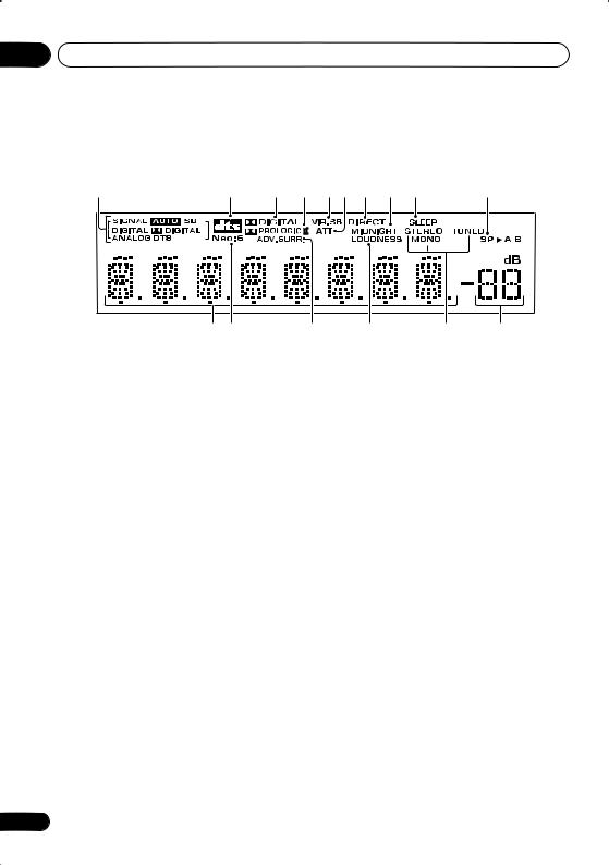
05 Controls and displays
Display
1 |
2 |
3 |
4 |
5 |
6 |
7 |
8 |
9 |
10 |
11 12 |
13 |
14 |
15 |
16 |
1 SIGNAL SELECT indicators
Lights to indicate the type of input signal assigned for the current component:
AUTO
3 2 DIGITAL
When the STANDARD mode of the receiver is on, this lights to indicate decoding of a Dolby Digital signal.
Lights when AUTO signal select is on.
SB
Depending on the source, this lights when a signal with surround back channel encoding is detected.
DIGITAL
Lights when a digital audio signal is detected.
2 DIGITAL
Lights when a Dolby Digital encoded signal is detected.
ANALOG
Lights when an analog signal is detected.
DTS
Lights when a source with DTS encoded audio signals is detected.
2 DTS
When the STANDARD mode of the receiver is on, this lights to indicate decoding of a DTS signal.
4 2 PRO LOGIC II
When the (STANDARD) Pro Logic II mode of the receiver is on, this lights to indicate Pro Logic II decoding.
5 VIR.SB
Lights during Virtual surround back processing.
6 ATT
Lights when INPUT ATT is used to attenuate (reduce) the level of the analog input signal.
7 DIRECT
Lights when source direct playback is in use. Direct playback bypasses the tone controls and channel levels for the most accurate reproduction of a source.
8 MIDNIGHT
Lights during Midnight listening.
9 SLEEP
Lights when the receiver is in sleep mode.
10 Speaker indicator
Shows the speaker system currently in use.
30
En
 Loading...