


Home Theater DVD Player HTD5540/12/98/94/93
Service
Service Manual
TABLE OF CONTENTS |
Page |
. Location of PCB Boards,Version Variation and Repair Scenario Matrix |
.....1-2 |
. Technical Specifications…………....………………………..............1-3
. Safety Instruction, Warning & Notes….……………………....….....1-4
. DFU Instruction.............................................................................. |
2-1 |
. Mechanical and Dismantling Instructions…………........................3-1 |
|
. Software Upgrades ........................................................................ |
4-1 |
. Trouble Shooting Chart………………………………………………. 5-1
. Wiring Diagram………………………………………..………..….….6-1
. Electrical Diagrams and Print-layouts..….…………………....….…7-1
. Votages and Waveforms for Connection Pins..….………………...8-1
. Pin Description & Block Diagrams of ICs..….………………..........9-1
. Set Mechanical Exploded view & Part list.…………………..….…10-1
. Revision List................................................................................. |
11-1 |
©Copyright 2013 Philips Consumer Electronics B.V. Eindhoven, The Netherlands
All rights reserved. No part of this publication may be reproduced, stored in aretrieval system or transmitted, in any form or by any means, electronic, mechanical, photocopying, or otherwise without the prior permission of Philips.
CLASS 1
LASER PRODUCT
GB 3141 785 39860
Version 1.0 |
Subject to modification |
PHILIPS |
|
Published by Arya & Stephen - 1309Printed in The Netherlands |
|
|
1-2
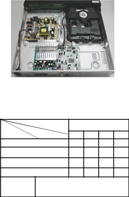
PCB Board Locations:
VERSION VARIATIONS
|
Type / Versions |
|
|
|
|
|
|
|
HTD5540 |
|
|
Board in used |
Service Policy |
/12 |
/98 |
/94 |
/93 |
MAIN BOARD |
|
M+C |
M+C |
M+C |
M+C |
POWER BOARD |
|
M+C |
M+C |
M+C |
M+C |
FRONT CONTROL BOARD |
M+C |
M+C |
M+C |
M+C |
|
LOADER |
|
M |
M |
M |
M |
Tips |
C -- Component Lever Repair |
|
M -- Module Lever Repair |
|
X -- Used |
Product specifications
 Note
Note
6SHFLÀFDWLRQV DQG GHVLJQ DUH VXEMHFW WR FKDQJH ZLWKRXW notice.
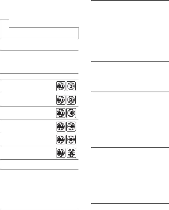
Region codes
The type plate on the back or bottom of the home theater shows which regions it supports.
Country DVD
Europe, United Kingdom
Asia Pacific, Taiwan, Korea
Latin America
Australia, New Zealand
Russia, India
China
Media formats
DVD-Video, DVD+R/+RW, DVD-R/-RW, DVD+R/-R DL, CD-R/CD-RW,Audio CD,
9LGHR &' 69&' 3LFWXUH ÀOHV 03 PHGLD
WMA media, DivX media, USB storage device
File formats
Audio: .mp3, .wma
1-3
Video: .avi, .divx, .mpg, .mpeg,Picture: .jpg, .jpeg
$PSOLÀHU
Total output power: 1000W RMS (30% THD)
Frequency response: 20 Hz-20 kHz / ±3 dB
Signal-to-noise ratio: > 65 dB (CCIR) / (A-weighted)
Input sensitivity:AUX: 2V
AUDIO IN: 1V
Video
Signal system: PAL / NTSC/Multi
HDMI output: 480i/576i, 480p/576p, 720p, 1080i, 1080p
Audio
S/PDIF Digital audio input:Optical:TOSLINK
Sampling frequency:
MP3: 32 kHz, 44.1 kHz, 48 kHzWMA: 44.1 kHz, 48 kHz
Constant bit rate:
MP3: 32 kbps - 320 kbpsWMA: 64 kbps - 192 kbps
Radio
Tuning range:
Europe/Russia/China:
FM 87.5-108 MHz (50 kHz)
$VLD 3DFLÀF /DWLQ$PHULFD )0
MHz (50/100 kHz)
Signal-to-noise ratio: FM 50 dB
Frequency response: FM 200 Hz-12.5 kHz / ±6 dB
USB
Compatibility: Hi-Speed USB (2.0)

1-4
Class support: USB Mass Storage Class (MSC)
File system: FAT16, FAT32, NTFSUSB port: 5V  , 500mA
Main unit
Power supply:
Europe/China/Russia/India: 220-240V~, 50 Hz
/DWLQ$PHULFD$VLD 3DFLÀF 9a
50-60 Hz
Power consumption: 140 W
6WDQGE\ SRZHU FRQVXPSWLRQ :Dimensions (WxHxD):
360 x 58 x 325 mmWeight: 2.3 kg
Subwoofer
Output power: 166 W RMS (30%THD)Impedance: 4 ohm
Speaker drivers: 165 mm (6.5") wooferDimensions (WxHxD):
178 x 300 x 343 mmWeight: 3.66 kg
Cable length: 3.3 m
HTD5540: 90 x 185 x 82 mm (front); 247 x 1090 x 242 mm (rear)
HTD5570: 247 x 1090 x 242 mm (front/rear)
Weight (front):
HTD5510: 0.53 kg/eachHTD5540: 0.53 kg/eachHTD5570: 2.66 kg/each
Weight (rear):
HTD5510: 0.56 kg/each
HTD5540/HTD5570: 2.72 kg/each
Cable length (front): 3.25 mCable length (rear): 10.25 m
Remote control batteries
1 x AAA-R03-1.5V
Laser
Type: Semiconductor laser GaAIAs (CD)Wave length: 650-662 nm (DVD),
785-795 nm (CD)
Output power: 6 mW (DVD), 7 mW (VCD/CD)
Beam divergence: 60 degrees.
Speakers
Center speaker:
Output power: 166 W RMS (30%THD)Speaker impedance: 4 ohm
Speaker drivers: 1 x 78 mm (3") full rangeDimensions (WxHxD):
223 x 100 x 80 mmWeight: 0.65 kg
Cable length: 2.25 m
Front/Rear speaker:
Output power: 4 x 166 W RMS (30% THD)
Speaker impedance: 4 ohm
Speaker drivers: 1 x 78 mm (3") full rangeDimensions (WxHxD):
HTD5510: 90 x 185 x 82 mm (front/ rear)

1-5
Safety instruction, Warning & Notes
Safety instruction
1. General safety
Safety regulations require that during a repair:
. Connect the unit to the mains via an isolation transformer.
.Replace safety components indicated by the symbol  , only by components identical to the original ones. Any other component substitution (other than original type) may increase risk of fire or electrical shock hazard.
Safety regulations require that after a repair, you must return the unit in its original condition. Pay, in particular, attention to the following points:
.Route the wires/cables correctly, and fix them with the mounted cable clamps.
.Check the insulation of the mains lead for external damage.
. Check the electrical DC resistance between the mains plug and the secondary side:
1)Unplug the mains cord, and connect a wire between the two pins of the mains plug.
2)Set the mains switch the “on” position (keep the mains cord unplug).
3)Measure the resistance value between the mains plug and the front panel, controls, and chassis bottom.
4)Repair or correct unit when the resistance
measurement is less than 1M .
5)Verify this, before you return the unit to the customer/user (ref. UL-standard no. 1492).
6)Switch the unit “off”, and remove the wire between the two pins of the mains plug.
2.Laser safety
This unit employs a laser. Only qualified service personnel may remove the cover, or attempt to service this device (due to possible eye injury).
Laser device unit |
|
Type |
: Semiconductor laser GaAlAs |
Wavelength |
: 650nm (DVD) |
|
: 780nm (VCD/CD) |
Output power |
: 7mW (DVD) |
: 10mW (DVD /CD) Beam divergence: 60 degree
Note: Use of controls or adjustments or performance of procedure other than those specified herein, may result in hazardous radiation exposure. Avoid direct exposure to beam.

1-6
Warning
1.General
.All ICs and many other semiconductors are susceptible to electrostatic discharges (ESD). Careless handing during repair can reduce life drastically. Make sure that, during repair, you are at the same potential as the mass of the set by a wristband with resistance. Keep components and tools at this same potential. Available ESD protection equipment:
1)Complete kit ESD3 (small tablemat, wristband, connection box, extension cable and earth cable) 4822 310 10671.
2)Wristband tester 4822 344 13999.
. Be careful during measurements in the live voltage section. The primary side of the power supply , including the heat sink, carries live mains voltage when you connect the player to the mains (even when the player is “off”!). It is possible to touch copper tracks and/or components in this unshielded primary area, when you service the player. Service personnel must take precautions to prevent touching this area or components in this area. A “lighting stroke” and a stripe-marked printing on the printed wiring board, indicate the primary side of the power supply.
.Never replace modules, or components, while the unit is “on”.
2. Laser
.The use of optical instruments with this product, will increase eye hazard.
.Only qualified service personnel may remove the cover or attempt to service this device, due to possible eye injury.
. Repair handing should take place as much as possible with a disc loaded inside the player.
.Text below is placed inside the unit, on the laser cover shield:
CAUTION: VISIBLE AND INVISIBLE LASER
RADIATION WHEN OPEN, AVOID EXPOSURE
TO BEAM.
Notes: Manufactured under licence from Dolby Laboratories. The double-D symbol is trademarks of Dolby Laboratories, Inc. All rights reserved.

1-7
6HUYLFH +LQWV
&$87,21
&+$5*(' &$3$&,7256 21 7+( 6(592 %2$5' 0$< '$0$*( 7+( '5,9( (/(&7521,&6 :+(1 &211(&7,1*$1(: '5,9( 7+$7¶6 :+< %(6,'(6 7+( 6$)(7< 0($685(6 /,.(
6:,7&+ 2)) 32:(5 6833/<
(6' 3527(&7,21
$'',7,21$/$&7,216 0867 %( 7$.(1 %< 7+( 5(3$,5 7(&+1,&,$1
7KH IROORZLQJ VWHSV KDYH WR EH GRQH ZKHQ UHSODFLQJ WKH GHIHFWLYH ORDGHU
'LVPDQWOLQJ RI WKH ORDGHU WR DFFHVV WKH (6' SURWHFWLRQ SRLQW LI QHFHVVDU\
|
|
6ROGHU WKH (6' SURWHFWLRQ SRLQW |
|
|
|
'LVFRQQHFW ÀH[IRLO FDEOH IURP WKH GHIHFWLYH ORDGHU
3XW D SDSHU FOLS RQ WKH ÀH[IRLO WR VKRUW FLUFXLW WKH FRQWDFWV ¿J
5HSODFH WKH GHIHFWLYH ORDGHU ZLWK D QHZ ORDGHU
5HPRYH SDSHUFOLS IURP WKH ÀH[IRLO DQG FRQQHFW LW WR WKH QHZ ORDGHU
5HPRYH VROGHU MRLQW RQ WKH (6' SURWHFWLRQ SRLQW
$77(17,21 7KH ODVHU GLRGH RI WKLV ORDGHU LV SURWHFWHG DJDLQVW (6' E\ D VROGHU MRLQW ZKLFK VKRUWFLUFXLWV WKH ODVHUGLRGH WR JURXQG )RU SURSHU IXQFWLRQDOLW\ RI WKH ORDGHU WKLV VROGHU MRLQW PXVW EH UHPRYH DIWHU FRQQHFWLRQ ORDGHU WR WKH VHW
 Solder Joint
|
|
(6' SURWHFWLRQ SRLQW LV DFFHVVLEOH IURP WRS RI ORDGHU
|
2QO\ DSSOLFDEOH IRU GHIHFWLYH ORDGHU QHHGHG WR EH VHQW EDFN WR VXSSOLHU IRU IDLOXUH DQDO\VLV DQG WR VXSSRUW EDFNFKDUJLQJ |
|
HYLGHQFH
7KLV LV DOVR DSSOLFDEOH IRU DOO SDUWQHUVKLS ZRUNVKRSV

1-8
Notes
Lead-Free requirement for service
INDENTIFICATION:
Regardless of special logo (not always indicated)
One must treat all sets from 1.1.2005 onwards, according next rules.
Important note: In fact also products a little older can also be treated in this way as long as you avoid mixing solder-alloys (leaded/ lead-free). So best to always use SAC305 and the higher temperatures belong to this.
Due to lead-free technology some rules have to be respected by the workshop during a repair:
x Use only lead-free solder alloy Philips SAC305 with order code 0622 149 00106. If lead-free solder-paste is required, please contact the manufacturer of your solder-equipment. In general use of solder-paste within workshops should be avoided because paste is not easy to store and to handle.
xUse only adequate solder tools applicable for lead-free solder alloy. The solder tool must be able
o To reach at least a solder-temperature of 400°C, o To stabilize the adjusted temperature at the
solder-tip
o To exchange solder-tips for different applications.
xAdjust your solder tool so that a temperature around 360°C – 380°C is reached and stabilized at the solder joint. Heating-time of the solder-joint should not exceed ~ 4 sec. Avoid temperatures above 400°C otherwise wear-out of tips will rise drastically and flux-fluid will be destroyed. To avoid wear-out of tips switch off un-used equipment, or reduce heat.
xMix of lead-free solder alloy / parts with leaded solder alloy / parts is possible but PHILIPS recommends strongly to avoid mixed
solder alloy types (leaded and lead-free). If one cannot avoid, clean carefully the
solder-joint from old solder alloy and re-solder with new solder alloy (SAC305).
xUse only original spare-parts listed in the Service-Manuals. Not listed standard-material (commodities) has to be purchased at external companies.
xSpecial information for BGA-ICs:
-always use the 12nc-recognizable soldering temperature profile of the specific BGA (for de-soldering always use highest lead-free temperature profile, in case of doubt)
-lead free BGA-ICs will be delivered in so-called ‘dry-packaging’ (sealed pack including a silica gel pack) to protect the IC against moisture. After opening, dependent of MSL-level seen on indicator-label in the bag, the BGA-IC possibly still has to be baked dry. This will be communicated via AYS-website.
Do not re-use BGAs at all.
xFor sets produced before 1.1.2005, containing leaded soldering-tin and components, all needed spare-parts will be available till the end of the service-period. For repair of such sets nothing changes.
xOn our website: www.atyourservice.ce.Philips.com
You find more information to: BGA-de-/soldering (+ baking instructions)
Heating-profiles of BGAs and other ICs used in Philips-sets
You will find this and more technical information within the “magazine”, chapter “workshop news”.
For additional questions please contact your local repair-helpdesk.

Your home theater
Congratulations on your purchase, and
ZHOFRPH WR 3KLOLSV 7R IXOO\ EHQHÀW IURP WKH support that Philips offers, register your home theater at www.philips.com/welcome.
Main unit
a Disc compartment
b Display panel
c (Open/Close)
Open or close the disc compartment.
d (Play/Pause)
Start, pause or resume play.
eSOURCE
Select an audio or video source for the home theater.
f  (Standby-On)
Switch the home theater on or to standby.
Remote control
This section includes an overview of the remote control.
2-1
a


 q b
q b

 p
p  o
o
c
d
e

 n
n
f |
|
g |
m |
h |
|
|
l |
i |
|
j |
k |
a (Standby-On)
Switch the home theater on or to standby.
When EasyLink is enabled, press and hold for at least three seconds to switch all connected HDMI CEC compliant devices to standby.
bSource buttons
DISC: Switch to disc source.Access or exit the disc menu when you play a disc.
2-2
AUDIO SOURCE: Select an audio input source.
RADIO: Switch to FM radio.
USB: Switch to USB storage device.
cNavigation buttons
Navigate menus.
In video mode, press left or right to fast backward or fast forward; press up or down to slow forward or slow backward (for DVD video only).
In radio mode, press left or right to search a radio station; press up or
GRZQ WR ÀQH WXQH D UDGLR IUHTXHQF\
dOK
&RQÀUP DQ HQWU\ RU VHOHFWLRQ
e  BACK
BACK
Return to a previous menu screen.
f  +/-
+/-
Increase or decrease volume.
g  (Mute)
Mute or restore volume.
h |
|
/ |
(Previous/Next) |
|
|
Skip to the previous or next track, |
|
|
|
FKDSWHU RU ÀOH |
|
|
|
In radio mode, select a preset radio |
|
|
|
station. |
|
iNumeric buttons
Select an item to play.
jSOUND
Select a sound mode.
kSURR
Select surround sound or stereo sound.
l  (Play/Pause)
Start, pause or resume play.
m (Stop)
Stop play.
n  OPTIONS
Access more play options while playing a disc or a USB storage device.
o  (Open/Close)
Open or close the disc compartment.
p (Home)
Access or exit the home menu.
qAUDIO SYNC
Select an audio language or channel.Press and hold to access audio delay
setting, then press Navigation buttons (left/right) to delay the audio to match the video.
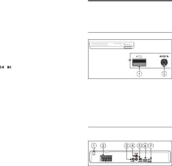
Connectors
This section includes an overview of the connectors available on your home theater.
Front
a (USB)
(USB)
Audio, video or picture input from a USB storage device.
bAUDIO IN
Audio input from an MP3 player (3.5mm jack).
Back connectors
aAC MAINS
Fixed AC power cable.
2-3
bSPEAKERS
Connect to the supplied speakers and subwoofer.
cVIDEO OUT
Connect to the composite video input on the TV.
dAUDIO IN-AUX
Connect to an analog audio output on the TV or an analog device.
eDIGITAL IN-OPTICAL
Connect to an optical audio output on the TV or a digital device.
fHDMI OUT (ARC)
Connect to the HDMI input on the TV.
gFM ANTENNA
Connect the supplied antenna for radio reception.

2-4
Connect and set up
This section helps you connect your home theater to aTV and other devices, and then set it up.
For information about the basic connections of your home theater and accessories, see the quick start guide.
 Note
Note
)RU LGHQWLÀFDWLRQ DQG VXSSO\ UDWLQJV VHH WKH W\SH SODWH at the back or bottom of the product.
Before you make or change any connections, make sure that all devices are disconnected from the power outlet.
Connect speakers
The speaker cables are color-coded for easy connection.To connect a speaker to your home theater, match the color on the speaker cable to the color on the connector.
Speaker position plays a critical role in setting up a surround sound effect. For best effect, position all the speakers towards the seating position and place them close to your ear level (seated).
SUB |
FRONT |
FRONT |
FRONT |
WOOFER |
|||
|
LEFT |
CENTER |
RIGHT |
|
REAR |
|
REAR |
|
LEFT |
|
RIGHT |
* The actual speaker shapes may vary from the illustration above.
 Note
Note
Surround sound depends on factors such as room shape and size, type of wall and ceiling, windows and
UHÁHFWLYH VXUIDFHV DQG VSHDNHU DFRXVWLFV ([SHULPHQW ZLWK WKH VSHDNHU SRVLWLRQV WR ÀQG WKH RSWLPXP VHWWLQJ for you.
Follow these general guidelines for speakers placement.
1Seating position:
This is the center of your listening area.
2FRONT CENTER (front center) speaker: Place the center speaker directly in front of the seating position, either above or below your TV.
3FRONT LEFT (front left) and FRONT RIGHT (front right) speakers:
Place the left and right speakers in the front, and at equal distance from the center speaker. Make sure that the left, right, and the center speakers are at equal distance from your seating position.
4REAR LEFT (rear left) and REAR RIGHT
(rear right) speakers:
Place the rear surround speakers to the left and right side of your seating position, either in line with it or slightly behind it.

5SUBWOOFER (subwoofer):
Place the subwoofer at least one meter to the left or right of theTV. Leave about 10-centimeter clearance from the wall.
Connect to TV
Connect your home theater to aTV to watch videos.You can listen to theTV audio through your home theater speakers.
Use the best quality connection available on your home theater and TV.
Option 1: Connect to TV through HDMI (ARC)
Best quality video
Your home theater supports HDMI version with Audio Return Channel (ARC). If your TV is HDMI ARC compliant, you can hear the TV audio through your home theater by using a single HDMI cable.
TV |
1Using a High Speed HDMI cable, connect the HDMI OUT (ARC) connector on your home theater to the HDMI ARC connector on the TV.
The HDMI ARC connector on the TV might be labeled differently. For details, see the TV user manual.
2On your TV, turn on HDMI-CEC operations. For details, see the TV user manual.
HDMI-CEC is a feature that enables CEC compliant devices that are connected through HDMI to be controlled by a single remote control,
2-5
such as volume control for both the TV and the home theater. (see 'Set up EasyLink (HDMI-CEC control)' on page 10)
3If you cannot hear the TV audio through your home theater, set up the audio manually.
Option 2: Connect to TV through standard HDMI
Best quality video
If your TV is not HDMI ARC compliant, connect your home theater to the TV through a standard HDMI connection.
TV |
1Using a High Speed HDMI cable, connect the HDMI OUT (ARC) connector on your home theater to the HDMI connector on the TV.
2Connect an audio cable to hear the TV audio through your home theater (see 'Connect audio fromTV and other devices' on page 9).
3On your TV, turn on HDMI-CEC operations. For details, see theTV user manual.
HDMI-CEC is a feature that enables CEC compliant devices that are connected through HDMI to be controlled by a single remote control, such as volume control for both the TV and the home theater. (see 'Set up EasyLink (HDMI-CEC control)' on page 10)

4If you cannot hear theTV audio through your home theater, set up the audio manually.
 Note
Note
If your TV has a DVI connector, you can use an HDMI/ DVI adapter to connect toTV. However, some of the features may not be available.
Option 3: Connect to the TV through composite video
Basic quality video
If your TV does not have HDMI connectors, use a composite video connection.A composite
FRQQHFWLRQ GRHV QRW VXSSRUW KLJK GHÀQLWLRQ video.
TV |
1Using a composite video cable, connect the VIDEO OUT connector on your home theater to the VIDEO IN connector on the TV.
The composite video connector might be labeled AV IN, COMPOSITE, or
BASEBAND.
2Connect an audio cable to hear theTV audio through your home theater (see 'Connect audio from TV and other devices' on page 9).
3When you watchTV programs, press SOURCE on your home theater repeatedly to select the correct audio input.
4When you watch videos, switch your TV to the correct video input. For details, see the TV user manual.
2-6
Connect audio from TV and other devices
Play audio fromTV or other devices through your home theater speakers.
Use the best quality connection available on your TV, home theater, and other devices.
 Note
Note
When your home theater and TV are connected through HDMI ARC, an audio connection is not required (see 'Option 1: Connect to TV through HDMI (ARC)' on page 8).
Option 1: Connect audio through a digital optical cable
Best quality audio
TV |
1Using an optical cable, connect the OPTICAL connector on your home theater to the OPTICAL OUT connector on the TV or other device.
The digital optical connector might be labeled SPDIF or SPDIF OUT.
2-7
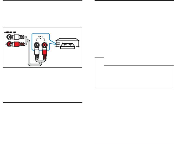
Option 2: Connect audio through analog audio cables
Basic quality audio
AUDIO INAUX |
VCR |
1Using an analog cable, connect the AUX connectors on your home theater to the AUDIO OUT connectors on the TV or other device.
Set up speakers
Set up the speakers manually to experience customized surround sound.
Before you start
Make the necessary connections described in the quick start guide, and then switch the TV to the correct source for your home theater.
1Press (Home).
2Select [Setup], and then press OK.
3Select [Audio] > [Speaker Setup].
4Press the Navigation buttons and OK to select and change:
[SpeakersVolume]: Set the volume level of each speaker.
[Speakers Delay]: Set the delay time for speakers which are placed closer to the seating position in order to obtain equal audio transmission from all the speakers.
Set up EasyLink (HDMI-CEC control)
This home theater supports Philips EasyLink, which uses the HDMI-CEC (Consumer Electronics Control) protocol. EasyLinkcompliant devices that are connected through HDMI can be controlled by a single remote control.
 Note
Note
Depending on the manufacturer, HDMI-CEC is known by many names. For information on your device, see the user manual of the device.
Philips does not guarantee 100% interoperability with all HDMI-CEC devices.
Before you start
Connect your home theater to the HDMICEC compliant device through HDMI connection.
Make the necessary connections described in the quick start guide, and then switch the TV to the correct source for your home theater.
Enable EasyLink
1Press  (Home).
2Select [Setup], and then press OK.
3Select [Video], and then press OK.
4Select [HDMI Setup] > [EasyLink Setup] > [EasyLink] > [On].
5On your TV and other connected devices, turn on HDMI-CEC control. For details, see the user manual of the TV or other devices.On your TV, set the audio output to
$PSOLÀHU LQVWHDG RI79 VSHDNHUV
For details, see the TV user manual.

2-8
EasyLink controls
With EasyLink, you can control your home theater,TV, and other connected HDMI-CEC compliant devices with a single remote control.[One Touch Play] (One-touch play): If onetouch play is enabled, press  (Standby-
On) on the remote control of your home theater to wake up the TV from standby.
[One Touch Standby] (One-touch standby): If one-touch standby is enabled, your home theater can switch to standby with the remote control of theTV or other HDMI-CEC devices.
[Sys Audio Control] (System audio control): If system audio control is enabled, the audio of the connected device is output through your home theater speakers automatically when you play the device.
[Audio Mapping] (Audio input mapping):If system audio control does not work, map the connected device to the correct audio input connector on your home theater.
 Note
Note
To change the EasyLink control settings, press  (Home), select [Setup] > [Video] > [HDMI Setup] > [EasyLink Setup] > [EasyLink].
To play the audio from theTV speakers, select [Off], and skip the following steps.
5Select [HDMI Setup] > [EasyLink Setup] > [Audio Mapping].
6Follow the onscreen instructions to map the connected device to the audio inputs on your home theater.
If you connect your home theater to theTV through an HDMI ARC connection, make sure that theTV
audio is mapped to the ARC input on your home theater.
Set up the audio
If you cannot hear the audio output of a connected device through your home theater speakers, do the following:
Check that you have enabled EasyLink on all the devices (see 'Set up EasyLink (HDMI-CEC control)' on page 10).
1
2
3
4
Press  (Home).
Select [Setup], and then press OK.
Select [Video], and then press OK.
Select [HDMI Setup] > [EasyLink Setup] > [Sys Audio Control] > [On].

3-1
Mechanical and Dismantling Instructions
Dismantling Instruction |
Detailed information please refer to the model set. |
|
The following guidelines show how to dismantle the player.
Step1: Open the top cover. Remove 2 screws on both sides and 4 screws on back panel,then open the cover.
(Figure 1)
Figure 1
Step2: Dismantle the loader.Open the tray,dismantle the CD door,remove 2 screws beside the loader. disconnect connectors(XP100,XP135,XP136),then pull up the loader.(Figure 2)
Figure 2
 Loading...