


 Loading...
Philips M1013A/M1019A/M1026B
Instructions for Use
IntelliVue G1/G5 and
Anesthetic Gas Module
M1013A/M1019A/M1026B
Patient Monitoring

Part Number M1013-9001C Printed in Germany 12/05 4512 610 12491
*M1013-9001C*

M1013-9001C
Table Of Contents
|
1 Using the Gas Analyzer |
1 |
Understanding the Gas Analyzer Display |
2 |
|
M1013A IntelliVue G1 & M1019A IntelliVue G5 Major Parts and Keys |
2 |
|
|
M1013A IntelliVue G1 / M1019A IntelliVue G5 Rear Panel |
3 |
M1026B Major Parts and Keys |
3 |
|
|
M1026B Rear Panel |
4 |
|
Watertrap M1657B |
4 |
Understanding the Gas Measurement |
5 |
|
|
M1013A IntelliVue G1 & M1019A IntelliVue G5 |
5 |
|
M1026B AGM |
5 |
Connecting Gas Analyzer Accessories |
5 |
|
Using the Gas Analyzer Setup Menus |
7 |
|
|
Choosing Numerics for Display |
7 |
|
Humidity Correction for CO2 |
8 |
|
Adjusting Wave Scales |
8 |
Changing the Apnea Alarm Delay |
9 |
|
Deriving Limit Alarms from awRR |
9 |
|
|
Alarms and Zero Calibration |
9 |
|
Automatic Alarm Suppression |
9 |
Agent Identification |
10 |
|
|
If Agent ID is Set to Manual |
10 |
|
If Agent ID is Set to Auto (M1019A IntelliVue G5 & M1026B AGM) |
10 |
|
Exchanging Agents (M1019A IntelliVue G5 & M1026B AGM) |
11 |
|
Agent ID During Emergence from Anesthesia |
|
|
(M1019A IntelliVue G5 & M1026B AGM) |
11 |
MAC Calculation |
11 |
|
|
Uncorrected MAC |
12 |
|
Ambient Pressure Corrected MAC (not available in the USA) |
12 |
|
Enhanced MAC Correction (not available in the USA) |
13 |
Removing Gas from the Circuit |
15 |
|
|
Returning the Gas Sample |
15 |
|
Removing the Gas Sample |
15 |
Entering Gas Analyzer Standby Mode |
16 |
|
Zero Calibration |
17 |
|
|
Automatic Zero Calibration |
17 |
|
M1013A IntelliVue G1 and M1019A IntelliVue G5 |
17 |
|
M1026B AGM |
17 |
|
Carrying Out Manual Zero Calibration |
17 |
|
Suppressing Zero Calibration |
17 |
Using the Gas Analyzer During a Cardiopulmonary Bypass |
18 |
|
Safety Information |
18 |
|
i

|
2 Maintenance and Troubleshooting |
21 |
Inspecting the Equipment and Accessories |
21 |
|
Inspecting the Cables and Cords |
21 |
|
Maintenance Task and Test Schedule |
21 |
|
Troubleshooting |
23 |
|
Disposing of the Gas Analyzer |
23 |
|
Disposing of Empty Calibration Gas Cylinders |
23 |
|
|
3 Installation and Specifications |
25 |
|
|
|
Intended Use |
25 |
|
Manufacturer’s Information |
26 |
|
|
Responsibility of the Manufacturer |
26 |
Symbols |
27 |
|
Installation Safety Information |
28 |
|
Installation Instructions |
28 |
|
Altitude and Barometric Pressure |
28 |
|
M1013A IntelliVue G1 & M1019A IntelliVue G5 Specifications |
29 |
|
|
Safety Specifications |
29 |
|
Physical and Electrical Specifications |
29 |
|
Environmental Specifications |
29 |
|
Measurement Specifications |
30 |
|
Interfering Gases and Vapours |
32 |
M1026B Specifications |
33 |
|
|
Safety Specifications |
33 |
|
Physical and Electrical Specifications |
33 |
|
Environmental Specifications |
34 |
Measurement Specifications |
35 |
|
|
Interfering Gases and Vapours |
37 |
Safety and Performance Tests |
38 |
|
|
Electromagnetic Compatibility (EMC) Specifications |
38 |
|
Accessories Compliant with EMC Standards |
38 |
|
Electromagnetic Emissions |
38 |
|
Electromagnetic Immunity |
39 |
|
Recommended Separation Distance |
40 |
|
4 Patient Alarms and INOPs |
41 |
|
|
|
Patient Alarm Messages |
41 |
|
Technical Alarm Messages (INOPs) |
43 |
|
|
5 Gas Analyzer Accessories |
47 |
|
|
|
|
6 Care and Cleaning |
49 |
|
|
|
General Points |
49 |
|
Cleaning |
50 |
|
Disinfecting |
50 |
|
ii

Gas Analyzer Accessories |
50 |
iii

iv

1
Using the Gas Analyzer
The M1013A IntelliVue G1, the M1019A IntelliVue G5 and the M1026B Anesthetic Gas Module (AGM), hereafter referred to as the “gas analyzers”, measure patients’ anesthetic and respiratory gases.The following table shows the main features and the patient monitor compatibility for the three gas analyzers:
|
Gases measured |
Agents |
|
|
|
Number of |
Number of measured |
Automatic |
|
Gas Analyzer |
Agent ID |
Compatibility |
||
|
|
|
||
M1013A IntelliVue G1 |
3 |
1 |
n/a |
IntelliVue MP20/30/40/50 |
M1019A IntelliVue G5 |
3 |
2 |
2 out of 5 |
IntelliVue MP20/30/40/50/60/70/80/90 |
M1026B AGM |
3 |
1 |
1 out of 5 |
IntelliVue MP40/50/60/70/80/90 and |
|
|
|
|
Philips ACMS; Philips V24/26 |
|
|
|
|
|
The gas analyzers measure the Airway Respiration Rate (awRR) and provide end tidal (et) and inspired (in) values for the following gases:
Respiratory Gases |
Anesthetic Agents |
|
|
Carbon dioxide (CO2) |
Halothane |
Nitrous oxide (N2O) |
Isoflurane |
Oxygen (O2) |
Enflurane |
|
Sevoflurane |
|
|
|
Desflurane |
|
|
The gas analyzers must only be used by qualified personnel.
1
1 Using the Gas Analyzer |
Understanding the Gas Analyzer Display |
Understanding the Gas Analyzer Display
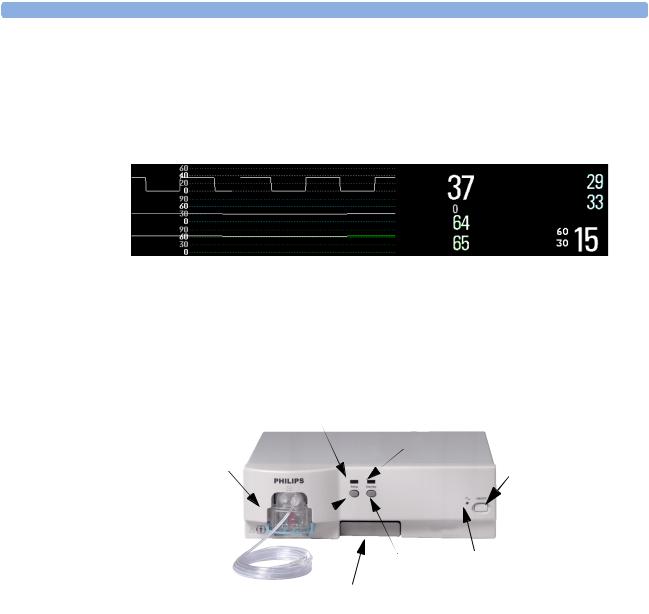
The gas analyzers can send waves and numerics for all measured gases for display on the monitor screen. This example shows the CO2, O2, and N2O waves and numerics. Your display may be configured to look different.
CO2 |
etCO2 |
etO2 |
|
|
|||
O2 |
imCO2 |
inO2 |
|
awRR rpm |
|||
N2O |
etN2O |
||
|
inN2O |
|
M1013A IntelliVue G1 & M1019A IntelliVue G5 Major Parts and Keys
Setup LED |
Standby LED |
Watertrap |
Power on/off |
|
|
Standby Key |
Power LED |
|
|
|
Setup Key |
Quick Mount Release |
|
The setup LED lights when the Setup Gas Analyzer menu is open, when the module is first switched on (for 5 - 10 seconds), and if there is a problem with the communication between the gas analyzer and the monitor. The standby LED lights up when the gas analyzer is in standby.
2

M1026B Major Parts and Keys |
1 Using the Gas Analyzer |
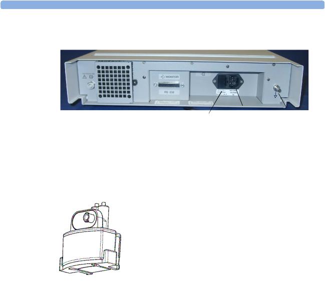
M1013A IntelliVue G1 / M1019A IntelliVue G5 Rear Panel
Power Inlet |
RJ-45 |
Gas Outlet |
|
Fuses |
Equipotential Grounding Terminal |
The RJ-45 connector is the interface connector for the Philips IntelliVue patient monitors.
WARNING • The M1013A IntelliVue G1 may only be used with the Philips IntelliVue MP20/30/40/50 patient monitors. Connections to other devices may result in a safety hazard.
•The M1019A G5 may only be used with the Philips IntelliVue MP20/30/40/50/60/70/80/90 patient monitors. Connections to other devices may result in a safety hazard.
Make sure that the anesthetic gas outlet at the rear of the module is connected to the gas scavenging system or the gas return line.
See your gas analyzer’s service guide for further information on connecting devices.
M1026B Major Parts and Keys
Airway Gases LED
Airway Gases Key
Power On/
Off switch
Power LED
Watertrap
The setup airway gases LED lights when the Setup Gas Analyzer menu is open, when the module is first switched on (for 5 - 10 seconds), and if there is a problem with the communication between the M1026B and the monitor.
3
1 Using the Gas Analyzer |
M1026B Major Parts and Keys |
M1026B Rear Panel
|
|
|
|
|
Power |
|
|
|
|
|
|
|
|
||
|
|
RS232 |
|
Equipotential |
|||
Gas Outlet |
Fuses |
||||||
Inlet |
|||||||
|
|
Connector |
|
Grounding |
|||
|
|
|
|
||||
Make sure all devices connected to the RS232 connectors are isolated. Make sure that the anesthetic gas outlet at the rear of the module is connected to the gas scavenging system or the gas return line.
See the M1026B Anesthetic Gas Module Service Guide for further information on connecting devices.
Watertrap M1657B
The watertrap prevents water and other fluids from passing into the gas analyzer and causing contamination and/or internal occlusions. It has a water reservoir in which fluids are collected, two water separation filters, and two shut-off fuses as a backup mechanism for the water separation filters.
The watertrap is for multi-patient use. It must be exchanged at least every two weeks or when watertrap is full.
4
Understanding the Gas Measurement |
1 Using the Gas Analyzer |
Understanding the Gas Measurement
M1013A IntelliVue G1 & M1019A IntelliVue G5
The M1013A IntelliVue G1 and the M1019A IntelliVue G5 use a technique called Non-Dispersive Infrared Gas Concentration Measurement (NDIR) to measure the concentration of certain gases.
The gases which can be measured by the M1013A IntelliVue G1 and the M1019A IntelliVue G5 absorb infrared (IR) light. Each gas has its own absorption characteristic. The gas is transported into a sample cell, and an optical IR filter selects a specific band of IR light to pass through the gas. For multiple gas measurement, such as in the M1013A IntelliVue G1 or the M1019A IntelliVue G5, there are multiple IR filters. The higher the concentration of gas in a given volume the more IR light is absorbed. This means that higher concentrations of IR absorbing gas cause a lower transmission of IR light. The amount of IR light transmitted after it has been passed through an IR absorbing gas is measured. From the amount of IR light measured, the concentration of gas present can be calculated. This calculation provides the gas measurement value. Oxygen is measured by an additional sensor in the M1013A IntelliVue G1 and the M1019A IntelliVue G5 using its paramagnetic properties. The gas is transported into a sample cell. The higher the oxygen concentration, the higher the measured effect. The oxygen concentration can be calculated from the amplitude of the effect.
NOTE The presence of organic cleaning solutions or gases containing freon may impact the accuracy of the infrared gas measurement.
M1026B AGM
The M1026B Anesthetic Gas Module uses a technique called Dispersive Infrared (DIR) to measure the concentration of certain gases. The gases measured (except oxygen) by the M1026B Anesthetic Gas Module absorb infrared (IR) light. Each gas has its own absorption characteristic. The gas is transported into a sample cell. A diffraction grating is used to scan the relevant wavelength range of the IR light that passes through the sample cell. The higher the concentration of gas the more IR light is absorbed, and from the amount of IR light measured, the concentration of gas present can be calculated.
Individual gases have an individual spectral fingerprint. A mathematical algorithm is used to analyze the spectrum and to identify the anesthetic agents in the gas. Oxygen is measured by an additional sensor in the M1026B Anesthetic Gas Module using its paramagnetic properties. The gas is transported into a sample cell. The higher the oxygen concentration, the higher the measured effect. The oxygen concentration can be calculated from the amplitude of the effect.
NOTE The presence of organic cleaning solutions or gases containing freon may impact the accuracy of the infrared gas measurement.
Connecting Gas Analyzer Accessories
The gas analyzer accessories and part numbers are listed in the accessories section.
1Insert the M1657B watertrap into the watertrap socket by gently pushing it up and in. Make sure that the watertrap snap lock clicks into place
2Connect the gas sample tubing to the Luer connector of the watertrap.
5

1 Using the Gas Analyzer |
Connecting Gas Analyzer Accessories |
3 Connect the other end of the gas sample tubing to the patient via the airway adapter.
2
 3
3
|
4 |
1 |
M1657B Watertrap |
1 |
2 |
Watertrap connector prongs |
|
5 |
3 |
Luer connector (gas sample inlet) |
|
|
|
4 |
Snap lock |
|
|
5 |
M1658A Gas Sample Tubing |
|
|
6 |
Gas sample port |
|
|
7 |
Airway Adapter, either |
|
|
|
13902A Elbow Airway Adapter |
|
6 |
|
or M1612A Straight Airway Adapter |
|
8 |
Connects to the patient |
|
|
7 |
9 9 |
Connects to the Anesthesia Machine |
|
|
8 |
|
WARNING Make sure that you do not accidentally connect the luer connector of the gas sample line to an infusion link or any other links in the patient vicinity.
6

Using the Gas Analyzer Setup Menus |
1 Using the Gas Analyzer |
CAUTION Airway Adapter: Use a Philips Airway Adapter listed in the Accessories section of this manual and position it so that the part connecting to the gas sample tube is pointing upwards. This prevents condensed water from passing into the gas sample tube and causing an occlusion. Philips airway adapters have a built-in port extending from the adapter wall, which reduces the risk of a blockage occurring.
Watertrap: To minimize the risk of internal contamination, never leave the gas analyzer running without a watertrap attached (except during a watertrap exchange).
Gas Sample Tube: Do not use the gas sample tube if it is kinked, as it may cause an occlusion or leakage.
Room Ventilation Make sure that the room in which the gas analyzer is used is well-ventilated with fresh air. Gases or fumes that mix with and contaminate the room air may degrade measurement accuracy. Use either a Gas Exhaust Return Filter/Gas Exhaust return Tubing to return gas samples to the breathing circuit or connect a scavenging system to the gas exhaust port and remove the gas sample. Note that Gas Exhaust return tubing may not be available for use in all geographies.
Do not use the gas analyzer in a hyperbaric chamber with oxygen enrichment. Also, the ambient air must be free of CO2 enrichment.
WARNING Ensure that the connections are tight. Any leak in the system can result in erroneous readings due to ambient air mixing with patient gases.
Using the Gas Analyzer Setup Menus
Many gas analyzer settings can be changed just like other measurement settings. These are described in the chapter on Basic Operation in the Instructions for Use of your patient monitor, only gas analyzerspecific settings are described here.
To change settings for individual gases, enter the setup menu for the individual gas:
♦select the measurement numeric on the monitor screen, or
♦select the required gas label in the Setup <Gas Analyzer> menu.
To change Gas Analyzer settings, enter the Setup <Gas Analyzer> menu:
♦select one of the gas analyzer numerics on the monitor screen and then select the menu item Setup <Gas Analyzer>, or press the Setup hardkey or Airway Gases hardkey on the gas analyzer.
Choosing Numerics for Display
For each gas the gas analyzer measures, you can choose which numerics are displayed with the waveform on the screen:
–et displays the endtidal numerics,
–in displays the inspiratory numerics,
–et+in displays both endtidal and inspiratory numerics.
–Off switches off measurement of that particular gas.
7

1 Using the Gas Analyzer |
Using the Gas Analyzer Setup Menus |
–MAC displays the minimum alveolar concentration of an anesthetic agent at which patients do not respond with movement to a painful stimulus.
–MACawk (MAC awake) displays the minimum alveolar concentration of an anesthetic agent at which patients respond to verbal command.
No waveforms or numerics will be shown for gases set to Off, and no alarms will be generated.
To change the displayed numeric, in the Setup <Gas Label> menu, select the label of the gas measured to call up a pop-up list of numerics available and then select the numeric you want to display.
As the inspired minimum is measured for CO2 (imCO2), the numeric label is im instead of in.
Humidity Correction for CO2
The gas analyzer is configured to correct the CO2 measurement for either Body Temperature Pressure Saturated (BTPS), to account for humidity in the patient’s breath, or Ambient Temperature Pressure Dry (ATPD).
♦In the Setup CO2 menu, see the menu item Humidity Corr. to see which correction applies. It is either Wet for BTPS or Dry for ATPD.
Please refer to the Measurement Specifications in the Installation and Specifications chapter of this manual for details on the humidity correction.
Adjusting Wave Scales
1 In the Wave menu or the Setup menu for the gas, select Scale.
2 Choose a suitable scale range from the pop-up list.
8

Changing the Apnea Alarm Delay |
1 Using the Gas Analyzer |
Changing the Apnea Alarm Delay
The apnea alarm delay time determines the time limit after which the monitor alarms if the patient stops breathing.
1 In the Setup CO2 menu, select awRR.
2 In the Setup awRR menu, select Apnea Time.
3 Choose the apnea alarm delay time.
WARNING The safety and effectiveness of the respiration measurement method in the detection of apnea, particularly the apnea of prematurity and apnea of infancy, has not been established.
Deriving Limit Alarms from awRR
1 In the Setup CO2 menu or in the Setup <Gas Analyzer> menu, select awRR.
2In the Setup awRR menu, select Alarms.
3Select On to derive alarms from the airway respiration signal or Off to disable them.
Alarms and Zero Calibration
When a zero calibration is in progress, the physiological alarm detection is suspended. When the calibration is finished, the gas analyzer resumes alarm detection. If an alarm condition is present after the zero calibration, the alarm will be activated within the specified alarm delay time.
WARNING If an apnea occurs during a zero calibration, the time delay between the start of apnea and the activation of the apnea alarm could be up to 24 seconds plus the configured apnea delay time. After startup or after continuous operation of the M1013A IntelliVue G1 or the M1019A IntelliVue G5 of 4 months or more the time delay could be up to 93 seconds plus the configured apnea time for a single time.
Automatic Alarm Suppression
Your monitor can be set to suppress alarms until it detects that a patient has been connected to the gas analyzer (when breathing is detected). This feature is called No Al til Breath and can be set to On or Off in the monitor’s Configuration Mode.
9

1 Using the Gas Analyzer |
Agent Identification |
Agent Identification
The following table shows the Agent Identification possibilities of the different gas analyzers:
Gas Analyzer |
Manual Agent |
Automatic Agent |
Number of agents |
|
Identification |
Identification |
identified |
|
|
|
|
M1013A IntelliVue G1 |
yes |
no |
n/a |
M1019A IntelliVue G5 |
no |
yes |
2 |
M1026B AGM |
yes |
yes |
1 |
|
|
|
|
NOTE Only the M1026B AGM allows switching the agent identification mode between Agent Id: Manual and Agent Id: Auto. Nevertheless, agent identification behavior for the M1013A IntelliVue G1 and the M1019A IntelliVue G5 is described below in the Manual Agent ID (M1013A) and the Automatic Agent ID (M1019A) sections.
Setting the agent identification mode to Agent Id: Manual lets you choose the anesthetic agent manually. If you choose the setting Agent Id: Auto, the gas analyzer automatically identifies the predominant anesthetic agent(s) in the breathing circuit.
♦To change the agent identification mode, in the Setup AGT menu, select Agent Id: to toggle between the settings Auto and Manual.
If Agent ID is Set to Manual
To change the agent monitored, when Agent Id is set to Manual:
♦In the Setup <Agent label> menu, select Agent to call up a pop-up list of available agents and select the agent you want to monitor. For example, Setup HAL.
M1026B only: If the manually selected agent does not match the agent detected, the INOP CHECK AGENT appears.
WARNING Make sure to select the correct agent for monitoring. Selecting the wrong agent will cause erroneous readings.
If Agent ID is Set to Auto (M1019A IntelliVue G5 & M1026B AGM)
As soon as the M1019A IntelliVue G5 or the M1026B AGM has detected the agent(s), a waveform and numerics for this agent appears on the monitor screen, if they are configured to be displayed. During the process of identification, the generic label AGT (AGT1 and AGT2 when using an IntelliVue G5) is shown as a placeholder.
For an anesthetic agent to be detected by automatic agent identification, its concentration must exceed the identification threshold. The presence of other substances in the patient’s breathing circuit such as methanol or acetone can influence the agent identification and lead to incorrect values and incorrect identification.
10

MAC Calculation 1 Using the Gas Analyzer
Exchanging Agents (M1019A IntelliVue G5 & M1026B AGM)
If the anesthetic agent administered to the patient changes, a mixture of both gases is detected by the M1019A IntelliVue G5 or the M1026B AGM during the transition. The time needed to complete the exchange depends on the type of anesthesia (low flow or high flow), and the characteristics of the agents administered (pharmacokinetics). During the exchange, you will see the INOP message AGT MIXTURE and (with AGM only) -?- next to the affected numerics.
AGM only: If you are using automatic agent identification, when one of the agents decreases below its threshold and the other agent predominates, the monitor will recognize the exchange.
M1013A IntelliVue G1 and M1026B AGM only: If you are using manual agent identification, you must change the agent in the Agent Setup menu to match the administered agent.
Agent ID During Emergence from Anesthesia (M1019A IntelliVue G5 & M1026B AGM)
If automatic agent identification is selected during emergence from anesthesia and the agent concentration falls below the identification threshold, the agent will no longer be identified. The agent label will remain on the display and the numeric will show 0.00 % (numeric unavailable with IntelliVue G5) until the monitor detects that a patient is no longer connected. After this, the generic label AGT (AGT1 / AGT2 for M1019A IntelliVue G5) will be shown.
♦To display the correct agent and value, change to manual identification and select the agent manually.(AGM only)
MAC Calculation
The MAC (Minimum Alveolar Concentration) value of an anesthetic gas or agent denotes the concentration at which 50% of a population of anesthetized patients do not respond with movement to a painful stimulus (e.g. a standardized incision through the skin). The MAC awake represents the concentration at which 50% of a population of anesthetized patients responds to verbal command.
The Philips IntelliVue patient monitors offer three configurable methods of MAC calculation:
•Uncorrected MAC
•Ambient Pressure Corrected MAC
•Enhanced MAC Correction
The preferred method must be set in configuration mode of your patient monitor. The total MAC and MACawk values can then be selected for display on your monitor. The sections below describe how these values are calculated with the different methods.
To switch the MAC and/or the MACawk parameter on, set MAC and /or MACawk to ON in the gas analyzer setup menu.
NOTE • The MACawk value can only be displayed if MAC Correction is configured to “Enhanced”.
•MAC Calculation is only available in IntelliVue patient monitors with software revision C.0 or higher.
•Ambient Pressure Corrected MAC and Enhanced MAC Correction are not available in the USA.
11

1 Using the Gas Analyzer |
MAC Calculation |
Uncorrected MAC
If the MAC Correction is configured to “Off” the uncorrected MAC is calculated. The MAC value is not corrected for ambient pressure, age, temperature or any other individual factors influencing the effect of volatile anesthetic agents.
In order to calculate the MAC value the standard 1MAC concentrations of anesthetic agents and nitrous oxide are required. The following table lists these concentrations (according to the EN ISO 21647:2004 standard). The values are based on the assumptions that the patient is 40 years old (except for Desflurane where 25 years are assumed), the body temperature is 37° and the atmospheric pressure is 760 mmHg (1 atm):
Agent |
Halothane |
Enflurane |
Isoflurane |
Desflurane |
Sevoflurane |
N2O |
1MAC |
0.77 vol% |
1.7 vol% |
1.15 vol% |
7.3 vol% |
2.1 vol% |
105 vol% |
|
|
|
|
|
|
|
For each volatile anesthetic agent detectable by the gas analyzer the MAC value for the specific agent (MAC(AA)) is calculated as follows:
etConc(AA) MAC(AA) = ----------------------------
1MAC(AA)
where AA = Anesthetic Agent and etConc = end-tidal concentration
In the same way, the MAC value for nitrous oxide (MAC(N2O) is derived from the measured value of the nitrous oxide end-tidal concentration (etConc(N2O)):
etCONC(N2O) MAC(N2O) = -----------------------------------
1MAC(N2O)
Finally, the total MAC value of nitrous oxide and the selected anesthetic agent is calculated as follows:
MAC = MAC(N2O) + MAC(AA)
NOTE Gas components (N2O and/or anesthetic agent) which are switched off, are not included in the total MAC computation.
Ambient Pressure Corrected MAC (not available in the USA)
If the MAC Correction is configured to “Amb. Pressure”, the MAC is corrected to reflect the effect of a different partial pressure at another altitude.
12
Loading...