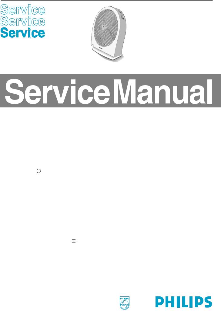
Philips HR3288 Service Manual

BOX FAN
HR 3288
Philips Domestic Appliances and Personal Care
PRODUCT INFORMATION
Features : safety tumble switch0
speed control with 2 hot and 3 cool settings thermostat
pilot light
adjustable inclination angle : 0° - 7.5° - 15° automatical resettable cut out
Switches : - ON / OFF louvre rotation
- selector switch for heating and cooling :
= Off
1= cool air, low speed
2= cool air, normal speed
3= cool air, extra speed
●= heating, normal 1100 Watts
●● = heating, extra fast 2200 Watts
Voltage / frequency : 220 - 240 V
Power consumption : heating : 2000 - 2400 Watts cooling : 77 Watts
Safety |
: insulation class |
|
|
|
|
|
|
|
|
Air displacement : ( cool ) max : 55 m3/min
This product meets the requirements regarding interference suppression on radio and TV.
Published by Philips Domestic Appliances and Personal Care |
Printed in the Netherlands |
© Copyright reserved |
Subject to modification |
4822 729 21836 97/06
PCS 88 818

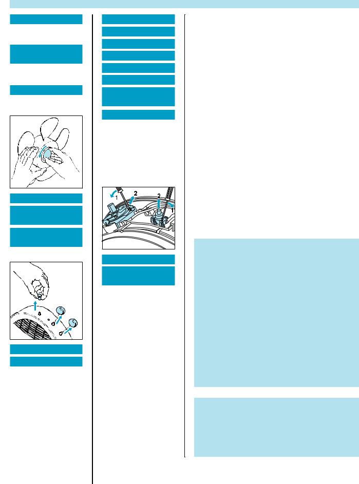
DISASSEMBLY ADVICE
GRILLE 1
remove SCREW A 2x remove LOCK PLATE 2
ORNAMENTAL
PLATE 3
remove GRILLE 1 remove SCREW B 3x
FAN BLADE 5
remove GRILLE 1 remove FAN CAP 4
LOUVRE BUTTON 6
SELECT. SWITCH
KNOB 8
THERMOSTAT
KNOB 10
to replace knobs
HEATING ELEMENT 13
MOTOR 14
remove BUTTON LOUVRE
SWITCH 6
remove KNOB SELECTOR
SWITCH 8 remove KNOB
THERMOSTAT 10 remove GRILLE 1
remove FAN BLADE 5 remove SCREW C (8x) remove REAR HOUSING
102
remove SCREW F (4x) remove MOTOR MOUNT
103
remove SCREW E (6x) remove SCREW G 4x remove / unsolder wires
LOUVRE SWITCH 7 SELECTOR SWITCH 9 THERMOSTAT 11 CORDSET 24
PILOT LIGHT + CAP 12 LOUVRE MOTOR 17
GEARWHEEL +
WASHERS 18
CAPACITORS 15 + 16
remove BUTTON LOUVRE
SWITCH 6
remove KNOB SELECTOR
SWITCH 8 remove KNOB
THERMOSTAT 10 remove GRILLE 1
remove SCEW C (8x)
remove REAR HOUSING 102
SAFETY SWITCH 19
BUTTON SAFETY
SWITCH 20
remove RUBBER FEET 24 remove SCREW H (4x) remove BOTTOM PLATE
105
remove / unsolder wiring
PARTS LIST
Pos. |
Description |
Service Code |
|
|
|
1 |
Grille |
4822 458 10606 |
2 |
Lock plate |
4822 466 11649 |
3 |
Ornamental plate |
4822 466 11651 |
4 |
Fan cap |
4822 462 10962 |
5 |
Fan blade |
4822 515 10063 |
|
|
|
6 |
Button louvre switch |
4822 410 11427 |
7 |
Louvre switch + item 106 |
4822 310 11065 |
8 |
Knob selector switch |
4822 410 11437 |
9 |
Selector switch + item 107 |
4822 310 11066 |
10 |
Knob thermostat |
4822 410 11428 |
11 |
Thermostat + item 108 |
4822 310 11067 |
12 |
Pilot light + cap |
4822 310 11068 |
13 |
Heating element |
4822 259 10284 |
14 |
Motor 220-240 V |
4822 361 11023 |
15 |
Capacitor 1.5 µF 400 V (1x) |
4822 121 10698 |
|
|
|
16 |
Capacitor 1.0 µF 400 V (5x) |
4822 121 10699 |
17 |
Louvre motor 240 V / 50 Hz |
4822 361 11022 |
18 |
Gearwheel + 2 washers |
4822 310 11069 |
19 |
Safety switch |
4822 276 13707 |
20 |
Button safety switch |
4822 410 11429 |
21 |
Fixing nut louvre grille |
4822 505 11248 |
22 |
Louvre grille + bearing bush |
4822 310 11071 |
23 |
Rubber foot (4x) |
4822 462 10989 |
24 |
Cord set EURO |
4822 321 11363 |
25 |
Thermal cut out (2x) |
4822 252 11282 |
|
|
|
IMPORTANT
*Cord set.
Due to the high wattage of the fan heater, only the specified cord set must be used.
*In some cases the connection points between wiring and electrical components have been insulated.
After replacement of a component, make sure that the electrical insolation of the connection points has been restored by fitting the regular sleeve.
If the regular sleeve cannot be used anymore, replace it with a new one or use insulating tape, taking care a proper and safe insulation is realized.
*After the product has been repaired, it should function properly and has to meet the safety requirements and legal regulations as laid down and offically established at this moment.
*Parts, with numbers from 100 and higher, cannot be ordered separately
Possible complaints :
1)The heater doesn’t function.
Action: Set the thermostat knob to the highest position
2)The overheating device has been activated.
Action: To reset the overheating device, remove the mains plug from the wall socket and let the heater cool down for 30 minutes.
PCS 88 819
 Loading...