


 Loading...
Ultrasound System
Getting Started
4708- 0027-03 Rev A |
April 2000 |
ATL Ultrasound |
|
|
P.O. Box 3003 |
|
|
Bothell, WA 98041-3003 |
|
|
USA |
Copyright E 2000 by ATL Ultrasound All rights reserved Printed in USA

Manufactured by ATL Ultrasound
22100 Bothell-Everett Highway Bothell, WA 98021-8431
USA
Telephone (425) 487-7000 or (800) 426-2670 Fax (425) 485-6080
ITT International 4740016 SMS UI Internet www.atl.com
CAUTION
United States federal law restricts this device to sale by or on the order of a physician.
“Advanced 3DI”, “Advanced Technology Laboratories”, “ATL”, “CHROMA”, “Cineloop”, “Color Power Angio”, “ENTOS”, “HDI”, “High Q”, and “Power Harmonic” are registered trademarks of ATL Ultrasound.
“DVS”, “Flash Contrast”, “High Definition”, “Power Motion”, “SonoCT”, “Tissue Specific”, and “WebLink” are trademarks of ATL Ultrasound.
Non-ATL Ultrasound product names may be trademarks or registered trademarks of their respective owners.
ATL Ultrasound products may be manufactured under or operate in accordance with one or more of the following United States patents and corresponding patents in other countries: U.S. Patent Numbers 4,581,636; 4,607,642; 4,543,960; 4,644,795; 4,887,306; 5,016,641; 5,123,415; 5,197,477; 5,255,682; 5,050,610; 5,226,422; 5,275,167; 5,207,225; 5,287,753; 5,215,094; 5,381,795; 5,386,830; 5,402,793; 5,390,674; 5,438,994; 5,471,989; 5,482,045; 5,476,097; 5,471,990; 5,456,257; 5,485,842; 5,482,047; 5,479,930; Re 35,148; 5,555,887; 5,617,863; 5,669,385; 5,645,066; D369,307; 5,634,465; 5,603,323; 5,706,819; 5,715,823; 5,718,229; 5,720,291; 5,879,303, 5,951,478; Re 36,564; 5,980,457; 5,961,462; 5,940,123; 5,908,389; 5,891,035; 5,860,924; 5,795,297; 5,846,200; 5,833,613. Other patent applications are pending in various countries.

Read This First
About Your Manual Set
This manual is part of a manual set. The manual set addresses the reader who is familiar with ultrasound techniques. Sonography training and clinical procedures are not included in the manual set. The manual set includes the following:
·Getting Started: Introduces you to basic system features and concepts. When you complete the procedures in this manual, you will know how to use these features and understand the concepts of system operation.
·Scanheads and Safety: Contains information about safety, scanheads, biopsy guides, transesophageal and laparoscopic scanheads, and acoustic output.
·Reference Manual: Contains information that supports and amplifies the procedures in Getting Started. It includes image management, maintenance, troubleshooting, specifications, references, and a glossary.
·Using Disinfectants and Gels: Contains information about compatible gels and disinfectants and disinfecting ATL products.
·Acoustic Output Tables: Contains information about mechanical and thermal index precision and accuracy, the acoustic output default tables, and the acoustic output tables.
·Medical Ultrasound Safety: Contains information about bioeffects and biophysics, prudent use, and implementing ALARA (as low as reasonably achievable).
·Operating Notes: Contains information that clarifies certain system responses that might be misunderstood or cause user difficulty.
About Your Manual Set on Compact Disc (CD)
A CD is included in a pocket on the inside back cover of the Getting Started manual. The CD contains the complete manual set, except for the Operating Notes. The instructions for using the CD are on the last page of the Getting Started manual.
Please take the time to use the CD, complete the brief survey card included with the manual set, and mail the survey card to us.
HDI 5000 Getting Started 4708-0027-03 |
1--1 |

Read This First
Conventions Used in This Manual
These conventions are used in this manual:
·All procedures are numbered. You must complete steps in the sequence they are presented to ensure a reliable result.
·Bulleted lists indicate general information about a particular function or procedure. They do not imply a sequential procedure.
·Control names appear in this manual like they appear on the system.
·Menu items or titles appearing on the display are shown in the manual like they appear on the display.
·The left side of the system is to your left as you stand in front of the system, facing the system.
·Scanheads and pencil probes both are referred to as scanheads, unless the distinction is important to the meaning of the text.
·“Select” means to place the cursor over an item and press SELECT once.
·“Double-select” means to place the cursor over an item, and quickly press SELECT two times, like double-clicking with a computer mouse. Pressing SELECT too slowly on double select will only highlight an item. Pressing it rapidly will initiate an action.
System Conventions
These conventions are used in the system:
·The software that runs the system uses graphic display elements similar to those used in many personal computers. References to these elements in the software or in the manual are defined in the glossary in the Reference Manual.
·On a menu, protocol, or other display, a highlight bar indicates that the item or name contained within the boundaries of the highlight bar is in the process of being selected. Pressing the SELECT control or other related control actually selects the item, assigns a value to a system parameter, or initiates the action related to the selected item.
·On a menu, an underlined letter indicates that pressing the underlined letter on the system keyboard will have the same effect as choosing the menu item with the trackball and the SELECT control.
·On the system keyboard, pressing the Superkey and another designated key, for example 2D Maps, allows you to change a system parameter without using a menu. Using the Superkey is a quick way to change a system parameter that normally appears on a menu.
1--2 |
HDI 5000 Getting Started 4708-0027-03 |

Read This First
·Pressing a key or control the first time initiates a mode change, function, or operation, or changes the value of a system parameter. Pressing the same key or control a second time resumes a previous mode or system parameter, cycles to the next setting, or ends the function or operation. All MENU controls work this way, and it can be quicker to press the MENU control than to select Close, especially to exit a submenu.
·On a menu, protocol, or other display, text that is lighter in color than the other text on the display indicates that the item or name contained within the boundaries is not available for selection in that menu, protocol, or display.
· |
A |
or |
indicates an option or alternative for selection. |
· |
A |
or |
indicates that an option or alternative has been selected. |
·Selecting Close from a menu or display removes the menu or display from the screen.
·Selecting + or -- increases or decreases the value of the parameter.
·An ellipsis ... on a menu indicates that a submenu is available from the selection.
·To highlight a menu, protocol, or other display item, use the trackball to move the cursor to the particular item.
·To enter text into a text field, use the keyboard.
·The softkeys, located on the lower right of the control panel, assume functions based on your control selections. For example, pressing VCR CTRL results in the softkeys assuming these VCR control functions: PLAY, PAUSE, STOP, FF (Fast Forward), and REWIND.
System Upgrades and Manual Set Updates
ATL Ultrasound is committed to innovation and continued improvement. Upgrades may be announced that consist of hardware or software improvements. Updated manuals will accompany those system upgrades.
Customer Comments
If you have questions about the manual set, or you discover an error in the manual set, please call the ATL Customer Service at (800) 433-3246; or if you are outside the USA, call the nearest ATL office, listed later in this section. You can also send electronic mail (e-mail) to ATL Technical Publications at the following address:
techpubs@corp.atl.com
HDI 5000 Getting Started 4708-0027-03 |
1--3 |

Starting an Exam
"To prepare the system for operation:
1.Ensure that the circuit breaker on the rear of the system (Figure 2--1) is set to OFF.
2.Ensure that the ON/STANDBY switch is set to STANDBY (Figure 2--1).
Circuit breaker
ON/STANDBY switch
STANDBY |
ON |
Figure 2--1. System Circuit Breaker and ON/STANDBY Switch Locations
HDI 5000 Getting Started 4708-0027-03 |
2--1 |

Starting an Exam
3.Plug the system power cord into a grounded outlet, rated for at least 15 amperes. Systems used in North America should only be connected to hospital-grade outlets.
4.Connect a scanhead to one of the scanhead receptacles (Figure 2--2).
a.Position the scanhead connector against the scanhead receptacle.
b.Turn the locking lever clockwise.
"To connect the footswitch assembly:
1.Locate the footswitch connector on the front of the system (Figure 2--2).
2.Connect the footswitch assembly to the footswitch connector.
"To connect physio transducers:
1.Prepare the ECG leads, phono, pulse, and auxiliary transducers, as necessary.
2.Connect the ECG, physio, and auxiliary connectors, as necessary, to the system receptacles (Figure 2--2).
2--2 |
HDI 5000 Getting Started 4708-0027-03 |
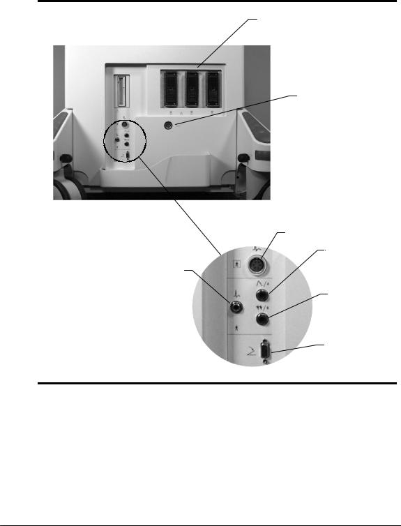
Starting an Exam
High-
Level
ECG
Scanhead receptacles
Pencil probe port
ECG
Pulse (Auxiliary Channel A)
Phono (Auxiliary Channel B)
Footswitch
Figure 2--2. Connection Receptacles
HDI 5000 Getting Started 4708-0027-03 |
2--3 |

Starting an Exam
"To turn on power to the system:
1.On the rear of the system, switch the circuit breaker switch to ON (Figure 2--1).
2.On the left side of the system, switch the ON/STANDBY switch (Figure 2--1) to ON.
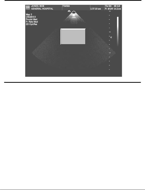
3.Wait about one minute while the system performs its initialization and self-test routine. A 2D display appears on the video monitor (Figure 2--3). (If a pencil probe is the only scanhead connected to the system, a scrolling display appears on the video monitor.)
Figure 2--3. 2D Display
"To turn off power to the system:
1.On the left side of the system, switch the ON/STANDBY switch to STANDBY (Figure 2--1).
2.The system displays a message, “Initiating power-down...Will power down when finished saving files.” and then the system shuts down.
3.On the rear of the system, switch the circuit breaker (Figure 2--1) to OFF.
2--4 |
HDI 5000 Getting Started 4708-0027-03 |

Starting an Exam
CAUTIONS S Standby does not result in an immediate cessation of system activity. A pow- er-down sequence occurs, similar to the initialization that occurs when power is turned on. Do not inadvertently cycle power, when this power-down sequence is occurring.
STo prevent electrical damage to the system or possible loss of patient data, after turning the system off, always wait 5 to 10 seconds before turning the power on again.
SPrior to disconnecting the power cord from the electrical outlet, switch the circuit breaker to the OFF position.
"To enter new patient data:
If you have the Worklist option or the Digital Video Streaming (DVS) option, the procedure for patient data entry differs from the following procedure. Refer to the “Image Manangement” section of theReference Manual, if your system has the Worklist option. Refer to the “Digital Video Streaming Option” section of the Reference Manual, if your system has the DVS option.
1.Press the Patient Data key to display the Patient Data Entry form (Figure 2--4).
Figure 2--4. Patient Data Entry Form
2. Select New to display the New Patient form (Figure 2--5).
HDI 5000 Getting Started 4708-0027-03 |
2--5 |
Starting an Exam
Figure 2--5. New Patient Form
3.Enter patient information: Last Name, First Name, MI (middle initial), ID, Accession
#, Date of Birth, and Gender, and press the Return key after each entry. Age is calculated from the date of birth you enter.
--With the Image Management option, if you do not enter an ID, the system will generate an ID and assign it to the patient.
--An accession number is an optional entry assigned to each patient file by an institution for internal information management purposes.
4.Press the Patient Data key, or select Close, to save the patient information and to exit the display.
"To edit patient data:
1.Press the Patient Data key to display the Patient Data Entry form (Figure 2--4).
2.Select Edit to display the Edit Patient form (Figure 2--6).
2--6 |
HDI 5000 Getting Started 4708-0027-03 |

Starting an Exam
Figure 2--6. Patient Data Entry: Edit Patient Form
3.Edit patient information: Last Name, First Name, MI (middle initial), ID, Accession #. Date of Birth, and Gender, and press the Return key after completing each field.Age is calculated from the date of birth you enter.
--With the Image Management option, if you do not enter an ID, the system will generate an ID and assign it to the patient.
--An accession number is an optional entry assigned to each patient file by an institution for internal information management purposes.
4.Press the Patient Data key, or select Close, to save the patient information and to exit the display.
HDI 5000 Getting Started 4708-0027-03 |
2--7 |

Starting an Exam
"To enter study data:
1.Select Study Data on the Patient Data Entry form to display additional study data fields (Figure 2--7).
Figure 2--7. Study Data Form
Note Verify that the date and time are accurately displayed. You will need to press the Patient Data key to display the time and again to return to Patient Data Entry.
2.If necessary, change the units of measure on the Study Data form:
a.Select the units of measure to display a drop-down list. Units of measure include the following: for height, cm (centimeters) and in (inches); for weight, lb (pounds), oz (ounces), kg (kilograms), and gms (grams).
b.From the drop-down list, select the units of measure you want.
3.Enter the patient’s height and weight in the units of measure shown on the display. Press the Return key after each entry. The patient’s body surface area will be calculated and displayed based on the height and weight you entered.
4.If appropriate, enter the LMP (last menstrual period) date. Press the Return key. The system automatically calculates and displays the gestational age using the LMP date, GA (LMP). A calculation of the estimated date of delivery by the last menstrual period, EDD (LMP), is also calculated and displayed.
-- If the LMP is unknown, you can enter an Estab. (Established) Due Date and then press Return. The system will calculate an LMP date and designate it with a c, for “calculated value.”
2--8 |
HDI 5000 Getting Started 4708-0027-03 |
Starting an Exam
5.Enter the Estab. Due Date and press the Return key.
6.For Twins, enter Y or N (Yes or No) and press the Return key.
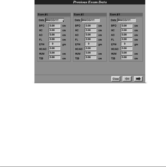
7.If previous ultrasound exam data exists, select Prev Exam Data. The Previous Exam Data form is displayed (Figure 2--8).
a.Enter the information into the Previous Exam Data form. There are 10 exams available, and you should enter the data in chronological order, beginning with
Exam #1.
b.When finished, select Close to exit the Previous Exam Data form.
Figure 2--8. Previous Exam Data
HDI 5000 Getting Started 4708-0027-03 |
2--9 |

Starting an Exam
"To select a scanhead for image optimization:
1.Ensure that the desired scanhead is securely connected to the scanhead receptacle.
2.Press the Scanhead key to display the Scanhead display, which shows the scanheads that are currently connected to the system (Figure 2--9).
3.Select the scanhead that you want. A list of clinical options is displayed based on the scanhead that you select (Figure 2--9).
Clinical options |
Tissue Specific |
|
presets |
||
|
||
|
|
|
|
Figure 2--9. Scanhead Display |
4.Select the clinical option that you want. A corresponding list of Tissue Specific presets displays across from the list of clinical options (Figure 2--9).
5.Select a Tissue Specific preset. The system initializes with the scanhead, clinical option, and the Tissue Specific preset you have selected (Figure 2--10).
Note If scanhead initialization fails: check the scanhead connector, reselect the scanhead, or select another scanhead.
2--10 |
HDI 5000 Getting Started 4708-0027-03 |
Starting an Exam
C5--2 40R
Abdomen/General
Initializing...
Figure 2--10. Tissue Specific Scanhead Initialization
HDI 5000 Getting Started 4708-0027-03 |
2--11 |

Using Setups
Setups are system parameters. There are three types of setups: system, Tissue Specific preset, and software. Changing any setup takes effect immediately. System setups are saved through a power cycle. Tissue Specific preset setups are only in effect until the current Tissue Specific preset is changed or a power cycle occurs. Software setups allow you or an ATL representative to install a temporary option on your system. You can use this option for a specified period of time before it is automatically disabled.
Tissue Specific preset setups can be saved as part of a user-defined Tissue Specific preset using the Quick Save key.
Image Management and Acquisition Parameters setups are addressed in detail in the “Image Management” and “Digital Video Streaming Option” sections of the Reference Manual. All setups and settings are explained in the glossary in the Reference Manual.
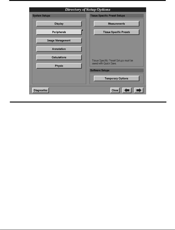
Directory of Setup Options
The Directory of Setup Options lists groups of system and Tissue Specific preset setups that are available in the system (Figure 3--1). Depending upon your system options, the content of your Directory of Setup Options may vary.
HDI 5000 Getting Started 4708-0027-03 |
3--1 |
Using Setups
Figure 3--1. Directory of Setup Options (Example)
3--2 |
HDI 5000 Getting Started 4708-0027-03 |

Using Setups
"To use the Directory of Setup Options:
1.Press the Setups key. The Directory of Setup Options appears (Figure 3--1).
2.Select one of the setup groups listed in the directory. The setups appear.
3.At the bottom of the setups displays, there are several control selections. Select the following, as necessary:
--System Defaults: Having changed setup values, you may want to revert to the original setup values without individually resetting all of the setups. Selecting System Defaults allows you to do that. System Defaults does not appear on the Directory of Setup Options; it appears on the setups displays.
--Close: Closes the display, exits Setups, and returns the system to the active imaging mode.
--Setups Directory: Displays the Directory of Setup Options.
--Left arrow: Moves back through the displays of the different setup groups.
--Right arrow: Moves forward through the displays of the different setup groups.
--Diagnostics: Appears on the Directory of Setup Options only; it provides access to the system diagnostics.
System Setups
"To change setups:
1.Select a setup group from the Directory of Setup Options.
2.Select the setup values or enter text into a text field for a setup.
3.Select Close or press the Setups key.
Perform the examples that follow to become familiar with changing setups, and then use these basic operations to change the range of setups as required for your uses.
HDI 5000 Getting Started 4708-0027-03 |
3--3 |
Using Setups
"To enter the name of the institution:
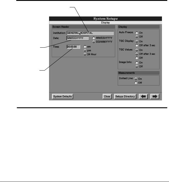
1.In Display setups, select the Institution field in the Screen Header area (Figure 3--2). The text entry cursor appears in the Institution field.
2.Enter the name of the institution.
3.Select Close to exit the Display setups and return to the imaging mode. The institution name that you entered appears on the image display.
Institution field
Date field
Time field
Figure 3--2. Display Setups
3--4 |
HDI 5000 Getting Started 4708-0027-03 |
Using Setups
"To enter the date:
1.In Display setups, select the desired date format (MM/DD/YY or DD/MM/YY) in the Screen Header area. The diamond changes shading to indicate selection of the date format (Figure 3--2). When you enter the date, it must correspond in format to this selection.
2.Move the cursor to the left side of the date entry field.
3.Press the SELECT control to activate text entry.
4.Enter the date in the format selected.
5.Select Close to exit the Display setups and return to the imaging mode. The date that you entered appears on the image display.
"To enter the time:
1.In Display setups, select the desired time format (am, pm, or 24 Hour) in the Screen Header area. The diamond changes shading to indicate selection of the time format (Figure 3--2). When you enter the time, it must correspond in format to this selection.
2.Move the cursor to the time entry field.
3.Press the SELECT control to activate text entry.
4.Enter the time in the format selected.
5.Select Close to exit the Display setups and return to the imaging mode. The time that you entered appears on the image display.
HDI 5000 Getting Started 4708-0027-03 |
3--5 |
Using Setups
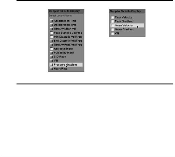
"To set the Doppler results display:
1.On the Directory of Setup Options, select Measurements. The Measurements setups appear.
2.Select the Doppler result that you want displayed during High Q Doppler analysis (Figure 3--3).
3.Repeat step 2 until you have selected up to six Doppler results for display (five for Cardiology clinical options).
4.Select Close to exit the Measurements setups.
5.During Doppler imaging, the Doppler results that you select from the Doppler Results Display list will be invoked for the number of heart cycles selected in the next procedure.
Cardiology
Non-Cardiology
Figure 3--3. Measurements Setups: Doppler Results Displays
3--6 |
HDI 5000 Getting Started 4708-0027-03 |

Using Setups
"To set the number of heart cycles by which High Q Doppler analysis will update:
1.On the Directory of Setup Options, select Measurements. The Measurements setups appear.
2.Select the High Q entry field to activate text entry (Figure 3--4).
3.Enter the number of heart cycles: the entry must be a number between 1 and 15.
4.Select Close to exit the Measurements setups.
5.The Doppler results will be updated every 1 to 15 heart cycles, depending upon your selection in the High Q Measurements setups.
Figure 3--4. Setting the High Q Update Interval
HDI 5000 Getting Started 4708-0027-03 |
3--7 |

Using Setups
Tissue Specific Preset Setups
Under a preset name, you can save the current setups and system control settings. ATL has optimized several presets and called them Tissue Specific presets. These presets are related to a clinical option and to a scanhead. They set up the system for specific tissue imaging and are intended to reduce the need for control adjustments.
The following procedures deal with creating your own presets, deleting presets, and transferring presets between systems.
"To use the Quick Save key to save a preset:
1.Ensure that the controls and setups are set for your application and scanhead.
2.Press the Quick Save key to display the dialog box (Figure 3--5).
3.To clear the Save current system settings as field, press the Backspace key. (Otherwise, the system default name will be used for your preset.)
4.Enter a name for your preset in the Save current system settings as field (Figure 3--5). You can enter five characters.
Name field
Figure 3--5. Quick Save Dialog Box
3--8 |
HDI 5000 Getting Started 4708-0027-03 |

Using Setups
5.Select Accept to save the preset.
6.To verify that your preset has been saved, press the Scanhead key. Your preset appears in the right column of the Scanhead display (Figure 3--6). You can now use this preset with the specific scanhead and clinical option.
Saved preset
Figure 3--6. User-defined Optimized Preset
HDI 5000 Getting Started 4708-0027-03 |
3--9 |

Using Setups
"To delete a preset:
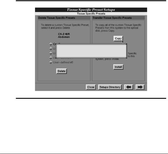
1.On the Directory of Setup Options, select Tissue Specific Presets. The Tissue Specific Presets Setups appear. (Figure 3--7).
2.Select the preset that you want to delete. (ATL Tissue Specific presets cannot be deleted.)
3.Select Delete to delete the selected presets. (Respond to the system dialog box as appropriate.) The custom preset is deleted from the list.
4.Select Close to exit the Directory of Setup Options.
Figure 3--7. Tissue Specific Presets Setups
3--10 |
HDI 5000 Getting Started 4708-0027-03 |
Using Setups
"To copy presets from a system to an optical disk:
1.On the Directory of Setup Options, select Tissue Specific Presets. The Tissue Specific Presets Setups appear. (Figure 3--7).
2.Insert a formatted optical disk into the disk drive.
3.Select Copy to copy the presets to the optical disk. A status message appears, and the indicator on the disk drive lights to indicate that the presets are copying to the optical disk (Figure 3--8).
4.Remove the optical disk:
a.Press NET/DISK.
b.Select Eject. The optical disk is ejected from the system optical disk drive.
Copying Tissue Specific Presets to the optical disk.
Please wait...
Figure 3--8. Copying Presets Message
HDI 5000 Getting Started 4708-0027-03 |
3--11 |
Using Setups
" To transfer presets from an optical disk to the system:
CAUTION |
|
|
|
|
Transferring presets from a system with one version of system software to anoth- |
||
|
|
||
|
|
er system with a different version of system software can corrupt the presets data- |
|
|
|
base. This can result in poor system performance. Before transferring presets |
|
|
|
between systems, ensure that the software versions are the same. Your customer |
|
|
|
service representative can supply you with this information. |
|
|
|
|
|
1.On the Directory of Setup Options, select Tissue Specific Presets. The Tissue Specific Presets Setups appear. (Figure 3--7).
2.Insert the formatted optical disk with presets into the optical disk drive.
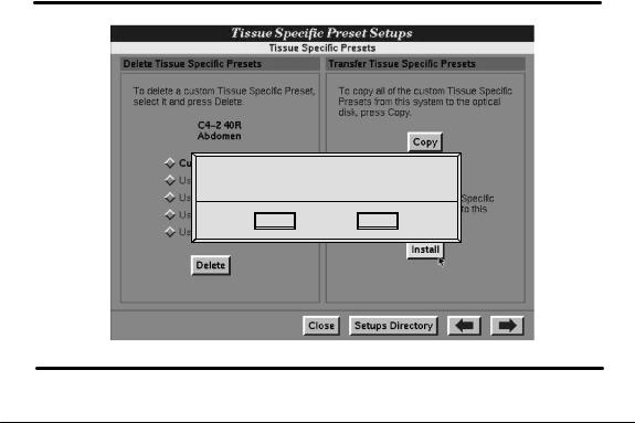
3.Select Install to transfer the presets from the optical disk to the system. The dialog box in Figure 3--9 appears. (Respond to the dialog box as appropriate.)
4.Remove the optical disk:
a.Press NET/DISK.
b.Select Eject. The optical disk is ejected from the system optical disk drive.
5.After installing the presets, the list of presets is not automatically updated. You must exit and re-enter the Tissue Specific Presets Setups to see the new list of presets.
Installing files from optical disk.
Do you want to overwrite the existing custom presets?
Install Cancel
Figure 3--9. Transferring Presets Dialog Box
3--12 |
HDI 5000 Getting Started 4708-0027-03 |
Using Setups
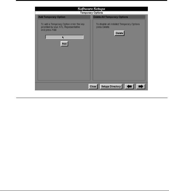
Software Setups
"To add a temporary option:
1.On the Directory of Setup Options, select Temporary Options. The Temporary Options setups appear (Figure 3--10).
Figure 3--10. Temporary Options Setups
2.Enter the “key” into the text entry field. (You can obtain the key from an ATL representative.)
3.Select Add. A dialog box appears describing the temporary software option and how to enable it (Figure 3--11).
HDI 5000 Getting Started 4708-0027-03 |
3--13 |
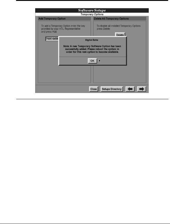
Using Setups
Figure 3--11. Adding a Temporary Software Option Dialog
4.To enable a temporary software option: turn off system power, wait several seconds, and then turn the system on.
5.When you turn the system on, a dialog box appears, describing the temporary option and the period of time it will remain enabled.
6.Select OK. The dialog is removed and imaging can begin. The temporary option is available for the period of time indicated in the dialog. Each time power is turned on, the dialog will be updated with the time remaining for any additional temporary options.
"To delete all temporary options:
1.On the Directory of Setup Options, select Temporary Options. The Temporary Options setups appear (Figure 3--10).
2.Select Delete. A dialog box appears, indicating that all temporary software options will be deleted.
3.Select OK. The dialog box is removed.
4.To update the system software options: turn off system power, wait several seconds, and then turn the system on.
3--14 |
HDI 5000 Getting Started 4708-0027-03 |
Loading...