


M O N I T O R / D E F I B R I L L A T O R
C O N T R O LS , C O N N E CT I O N S
A N D I N D I CATO R S

C O N T R O LS , C O N N E CT I O N S
A N D I N D I CATO R S
External Power |
SYNC |
|
Mark |
|
Event |
Sync |
Lead
Select
Alarm
Pause
Event
Summary Soft Navigation
Keys
Ready For
 Use (RFU)
Adult
Dose
|
|
fib |
|
100 120 |
150 |
|
|
|
l |
D |
e |
70 |
|
170 |
|
Therapy Knob |
|
M |
30 |
|
|
Energy |
1 |
|
||
ua |
|
50 |
|
|
200 |
|
|
|
an |
|
|
|
|
Select |
|
|
|
|
20 |
|
|
|
|
|
|
|
|
15 |
|
On Off |
Charge |
2 |
Charge |
Data |
|
|
Pacer |
|
On |
|||||
|
|
1-10 |
|
|
|
|
|
|
|
Monitor |
|
AED Shock |
|
|
Card |
||
|
|
|
|
|
|
3 |
Shock |
|
|
|
|
|
|
|
|
|
|
|
|
|
|
|
|
|
Printer |
|
|
|
|
|
|
|
|
Printer |
|
|
|
|
|
|
|
|
Door Latch |
|
|
|
|
|
|
|
|
|
|
|
|
|
Menu |
|
Speaker |
|
||
|
|
|
|
Select |
|
|
|
|
 Therapy
Connector
CO2 Inlet
CO2
Outlet
Temp
 CO2
CO2
Invasive
Pressure 1
|
Invasive |
|
Pressure 2 |
1 |
NBP |
|
2 |
|
ECG |
|
|
|
|
ECG |
SpO2 |
ECG Out |
ECG |
(Sync) |
|
Jack |
|
Battery/AC |
Bed Rail Hook |
Mount |
|
Compartment B |
Battery |
|
|
|
Compartment |
|
A |
LAN |
Battery |
Connection |
|
RS 232 |
|
Serial Port |
|
AC Power Module |
DC Power Input |
453564042471 Edition 1 September 2006
*453564042471*
*1*
M O N I T O R / D E F I B R I L L A T O R

M O N I T O R / D E F I B R I L L A T O R
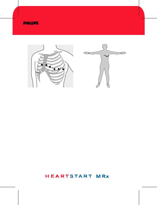
1 2 - L E A D E C G
1 2 - L E A D E C G
Electrode Placement for 12-Lead ECG
Acquiring the 12-Lead ECG
1.Turn the Therapy Knob to Monitor.
2.Press the 12-Lead soft key.
3.Check for good signal quality.
4.Press the Start Acquire soft key. If prompted, enter patient age and sex.
5.Keep the patient still during the 10-second acquisition period.
Accessing Stored 12-Lead Reports
1.Press the Menu Select  button.
2.Use the Navigation buttons to select Reports.
Reports for the current patient are listed by date and time.
3.Use the Navigation buttons to select a report and press the Menu Select button.
4.Select Print, Copy, or Delete, and press the Menu Select button.
5.To select another report, repeat steps 1 through 4.
453564042471 Edition 1 September 2006
*453564042471*
*1*
M O N I T O R / D E F I B R I L L A T O R

M O N I T O R / D E F I B R I L L A T O R
A L A R M S

U S I N G A L A R M S
Responding to Alarms
1.Check the patient.
2.Identify the alarm(s) indicated.
3.Silence the alarm(s) by pressing the Menu Select  button or one of the Navigation buttons.
4.Address the alarm condition by selecting one of the following options: Alarms Off - Turn the monitoring parameter's alarms off, displaying 
next to the parameter value.
Acknowledge - Recognize that the alarm condition is present, without further action. As the default option, Acknowledge always appears when an alarm occurs.
New Limits - Adjust parameter alarm limits accordingly.
Note: For only Heart Rate/Arrhythmia alarms, your options are either
Acknowledge or Acknowledge and New Limits, depending on the alarm.
Checking/Adjusting Alarm Limits
Alarm limits are preset for your device based on its configuration and the patient type. When alarms are on, alarm limits are visible next to the measurement's numeric value.
To adjust an alarm limit setting:
1.Press the Menu Select  button.
2.Select Measurements/Alarms and press the Menu Select button.
3.Select the desired measurement from the menu and press the Menu Select button.
4.Select (measurement) Limits from the menu and press the Menu Select button.
5.Adjust the limit and press the Menu Select button.
453564042471 Edition 1 September 2006
*453564042471*
*1*
M O N I T O R / D E F I B R I L L A T O R

M O N I T O R / D E F I B R I L L A T O R
M O N I TO R I N G
CA R B O N D I OX I D E

M O N I TO R I N G C O 2
Using the Nasal FilterLine
1.Attach the FilterLine tubing to the CO2 Inlet port.
2.Check that both nostrils are clear.
3.Position the nasal FilterLine on the face by inserting the tips into the nostrils.
4.Pass the FilterLine tubing over the ears, then slide the sleeve up the tubing toward the neck to a comfortable fit under the chin.
5.If using dual purpose FilterLine tubing, connect the green tubing to the oxygen source.
6.Check the positioning of the FilterLine regularly to ensure proper function.
Using the FilterLine and Airway Adapter
1.Attach the FilterLine tubing to the CO2 Inlet port.
2.Connect the wide end of the airway adapter to the endotracheal tube.
3.Connect the narrow end of the airway adapter to the ventilator tubing or manual resuscitator.
Measuring EtCO2 and AwRR
The CO2 waveform is automatically displayed in the configured Wave Sector when the FilterLine is connected to the CO2 Inlet port. The measurement values for End-Tidal CO2 (EtCO2) and Airway Respiration Rate (AwRR) are displayed in Parameter Block 2 as shown below.
SpO2 % EtCO2 mmHg AwRR rpm
100 90 |
34 30 |
18 |
8 |
100 |
50 |
|
30 |
453564042471 Edition 1 September 2006
*453564042471*
*1*
M O N I T O R / D E F I B R I L L A T O R

M O N I T O R / D E F I B R I L L A T O R
M O N I TO R I N G
E C G
 Loading...