


 Loading...
H E A R TS TA R T X L
S e r v i c e M a n u a l
M 473 5 A

Service Manual
M4735A HeartStart XL
Defibrillator/Monitor

Notice
About This Edition
Edition 5
Printed in the USA
Publication number M4735-90900
The information in this manual applies to the M4735A HeartStart XL Release Main 20 and earlier This information is subject to change without notice.
Philips shall not be liable for errors contained herein or for incidental or consequential damages in connection with the furnishing, performance, or use of this material.
Edition History
Edition 1, October 1, 2000
Edition 2, February 2003
Edition 3, October 2004 Edition 4, July, 2005 Edition 5, April, 2006
Copyright
Copyright © 2006
Koninklijke Philips Electronics N.V
All rights are reserved. Reproduction in whole or in part is prohibited without the prior written consent of the copyright holder.
Use of supplies or accessories other than those recommended by Philips Medical Systems may compromise product performance.
Warning
Radio Frequency (RF) interference from nearby transmitting devices may seriously degrade performance of the M4735A HeartStart XL Defibrillator/ Monitor. Electromagnetic compatibility with surrounding devices should be assessed prior to using the defibrillator.
THIS PRODUCT IS NOT INTENDED FOR HOME USE.
IN THE U.S., FEDERAL LAW RESTRICTS THIS DEVICE TO SALE ON OR BY THE ORDER OF A PHYSICIAN.
Manufacturer
Philips Medical Systems
3000 Minuteman Road Andover, MA USA 01810-1099
Medical Device Directive
The M4735A Defibrillator/Monitor complies with the requirements of the Medical Device Directive 93/42/EEC
and carries the 
 0123 mark accordingly.
Authorized EU-representative:
Philips Medizin Systeme Böblingen GmbH
Hewlett Packard Str. 2 71034 Böbingen Germany
Canada EMC:ICES-001
For the Declaration of Conformity Statement, please see the Philips Medical web site at http://incenter.medical.philips.com/ PMSPublic. Scroll over the Quality and Regulatory Tab located in the upper left corner of the window. Click to select Regulatory by Modality. Then click to select Defibrillators and select the entry for Declaration of Conformity (DoC).
China:
After sales service: Beijing MEHECOPHILIPS Medical Equipment Service Center
After sales service address: No. 208, 2nd District, Wang Jing Li Ze Zhong Yuan, Chao Yang District, Beijing Postal Code: 100102
Telephone: 010-64392415 Registration Number: SFDA(I)20043212740 Product standard number: YZB/USA 2764-21
ii

|
|
|
This manual uses the following text conventions: |
|
|
|
|
|
|
|
Printed and On-Line |
|
|
|
|
|
|
|
|
WARNING |
|
|
Warning statements describe conditions or actions that can result in personal injury |
|
|
|
or loss of life. |
|
|
|
|
|
|
|
|
|
|
|
|
|
|
|
|
|
|
|
|
CAUTION |
|
|
Caution statements describe conditions or actions that can result in damage to |
|
|
|
the equipment or loss of data. |
|
|
|
|
|
|
|
|
|
|
|
|
|
|
|
|
|
|
|
|
|
|
|
|
NOTE |
|
|
Notes contain additional information on servicing this product. |
|
|
|
|
|
|
|
|
TIP:
Tips provide hands-on insight into servicing this product.
|
|
Text |
represents messages that appear on the display |
|
|
|
|
|
represents softkey labels that appear on the display |
|
|
|
Softkey |
|
|
|
|
above or below the button to which they correspond |
|
|
|
|
|
|
|
|
|
|
|
On-Line Only
Hypertext
represents hypertext links, which will display as blue; click on the link to go to that destination, then click on the destination to return.
iii

|
Contents |
|
Introduction |
|
|
Who Should Use this Manual .................................................................................... |
1-1 |
|
Overview .................................................................................................................... |
1-1 |
|
Web-Based Training ....................................................................................................... |
1-1 |
|
Defibrillator/Monitor ...................................................................................................... |
1-2 |
|
Batteries .......................................................................................................................... |
1-2 |
|
Installation ...................................................................................................................... |
1-3 |
|
Upgrades ......................................................................................................................... |
1-3 |
|
Preventive Maintenance .................................................................................................. |
1-3 |
|
Repair Philosophy ........................................................................................................... |
1-3 |
|
Performance Verification and Safety Tests |
|
|
Overview .................................................................................................................... |
2-1 |
|
Chapter Contents ............................................................................................................. |
2-1 |
|
Required Testing Levels ............................................................................................. |
2-2 |
|
External Repairs/No Trouble Found ............................................................................... |
2-2 |
|
Printer .............................................................................................................................. |
2-3 |
|
Internal Repairs ............................................................................................................... |
2-3 |
|
Test and Inspection Matrix ......................................................................................... |
2-4 |
|
Test Equipment ........................................................................................................... |
2-9 |
|
Configuration and Diagnostic Modes ...................................................................... |
2-10 |
|
Configuration Mode ...................................................................................................... |
2-10 |
|
Diagnostic Mode ........................................................................................................... |
2-11 |
|
The Language Support Tool ..................................................................................... |
2-12 |
|
Using the Language Support Tool ................................................................................ |
2-12 |
|
Performance Verification Tests ................................................................................ |
2-14 |
|
Visual Inspection ........................................................................................................... |
2-15 |
|
Functional Checks ......................................................................................................... |
2-17 |
|
Diagnostic Tests ............................................................................................................ |
2-21 |
|
Safety Tests .................................................................................................................. |
2-42 |
|
Battery Capacity Test .................................................................................................... |
2-46 |
|
Troubleshooting |
|
|
Overview .................................................................................................................... |
3-1 |
|
Chapter Contents ............................................................................................................. |
3-1 |
|
Repair Philosophy ........................................................................................................... |
3-1 |
|
Equipment Required ....................................................................................................... |
3-1 |
|
Troubleshooting and Repair Methodology ................................................................ |
3-2 |
|
Methodology Overview .................................................................................................. |
3-2 |
|
Evaluate ...................................................................................................................... |
3-3 |
|
Troubleshoot ............................................................................................................... |
3-5 |
|
System Errors .................................................................................................................. |
3-5 |
|
v

Contents
Repair ......................................................................................................................... |
3-6 |
Check the repair .............................................................................................................. |
3-6 |
Verify .......................................................................................................................... |
3-7 |
Troubleshooting Tables .............................................................................................. |
3-8 |
Using the Tables ............................................................................................................. |
3-8 |
General Problems ....................................................................................................... |
3-9 |
Unit Unresponsive ........................................................................................................... |
3-9 |
Error Codes ................................................................................................................... |
3-11 |
System Messages .......................................................................................................... |
3-13 |
Momentary Messages ................................................................................................... |
3-16 |
Audio Tones ................................................................................................................ |
3-18 |
Extended Self Test Failures .......................................................................................... |
3-19 |
Operational Problems ............................................................................................... |
3-20 |
ECG Monitoring ......................................................................................................... |
3-20 |
SpO2 Monitoring ......................................................................................................... |
3-23 |
Defibrillation and Cardioversion ................................................................................. |
3-24 |
Pacing ............................................................................................................................ |
3-26 |
Printer ........................................................................................................................... |
3-27 |
Display .......................................................................................................................... |
3-28 |
Audio ............................................................................................................................ |
3-29 |
Controls ......................................................................................................................... |
3-30 |
Battery and Charging Circuits ...................................................................................... |
3-31 |
Data Card ...................................................................................................................... |
3-32 |
Calling for Service ................................................................................................... |
3-33 |
North America .............................................................................................................. |
3-33 |
Latin America ............................................................................................................... |
3-33 |
Europe ........................................................................................................................... |
3-33 |
Asia/Asia Pacific ........................................................................................................... |
3-34 |
Equipment Information ................................................................................................. |
3-35 |
Removal and Replacement
Overview .................................................................................................................... |
4-1 |
Chapter Contents ............................................................................................................. |
4-1 |
Servicing Notes .......................................................................................................... |
4-1 |
Key Components ............................................................................................................. |
4-1 |
Removal, Handling, and Replacement ........................................................................... |
4-2 |
Tool Requirements .......................................................................................................... |
4-3 |
Disposal .......................................................................................................................... |
4-4 |
External Assemblies ................................................................................................... |
4-5 |
User Replaceable Parts and Accessories ......................................................................... |
4-6 |
User Maintenance ........................................................................................................... |
4-6 |
Printer Assembly ............................................................................................................. |
4-7 |
Battery Cover ................................................................................................................ |
4-11 |
Main Fuse ..................................................................................................................... |
4-13 |
vi

|
Contents |
|
Battery Eject Assembly ................................................................................................ |
4-15 |
|
Data Card Door ............................................................................................................. |
4-17 |
|
Energy Select Knob .................................................................................................... |
4-19 |
|
Paddle Holders .............................................................................................................. |
4-20 |
|
Labels ............................................................................................................................ |
4-22 |
|
Label Descriptions ........................................................................................................ |
4-22 |
|
Removing and Replacing Labels .................................................................................. |
4-25 |
|
Opening the Case ..................................................................................................... |
4-26 |
|
Discharge the Power Supply Capacitors ...................................................................... |
4-26 |
|
Separate the Case ........................................................................................................ |
4-28 |
|
Discharge the Defibrillator Capacitor .......................................................................... |
4-32 |
|
Identifying Internal Subassemblies ............................................................................... |
4-34 |
|
Internal Assemblies - Top Case ................................................................................ |
4-35 |
|
Lithium Backup Battery ................................................................................................ |
4-36 |
|
Control PCA ................................................................................................................ |
4-38 |
|
Shield Plate ................................................................................................................... |
4-42 |
|
Keyscan PCA (EL Display) .......................................................................................... |
4-44 |
|
Keyscan PCA (LCD Display) ....................................................................................... |
4-52 |
|
Bezel Assembly .......................................................................................................... |
4-59 |
|
Energy Select Switch .................................................................................................... |
4-63 |
|
Display Assembly (EL Display) ................................................................................... |
4-65 |
|
Display Assembly (LCD Display) ................................................................................ |
4-68 |
|
Hooded Plastic Shield ................................................................................................... |
4-71 |
|
Parameter PCA .............................................................................................................. |
4-72 |
|
SpO2 PCA .................................................................................................................. |
4-78 |
|
ECG Connector ............................................................................................................. |
4-81 |
|
SpO2 Connector ............................................................................................................ |
4-84 |
|
Speaker ....................................................................................................................... |
4-86 |
|
AC Mains Connector .................................................................................................... |
4-88 |
|
ECG Out (Sync) Connector .......................................................................................... |
4-91 |
|
Pacer Keypad ................................................................................................................ |
4-92 |
|
Replacement Top Case .................................................................................................. |
4-97 |
|
Internal Assemblies - Bottom Case ........................................................................ |
4-101 |
|
Battery PCA ................................................................................................................ |
4-102 |
|
Defibrillator Capacitor ................................................................................................ |
4-106 |
|
Power PCA .................................................................................................................. |
4-108 |
|
Power Supply .............................................................................................................. |
4-112 |
|
Patient Connector ........................................................................................................ |
4-118 |
|
Replacement Bottom Case .......................................................................................... |
4-121 |
|
Closing the Case ..................................................................................................... |
4-123 |
|
Replacement Parts |
|
|
Overview .................................................................................................................... |
5-1 |
|
Chapter Contents ............................................................................................................. |
5-1 |
|
Ordering Replacement Parts .......................................................................................... |
5-1 |
|
vii

Contents
Ordering Supplies and Accessories |
................................................................................ 5-1 |
Key Components ........................................................................................................... |
5-2 |
Special Tools .............................................................................................................. |
5-3 |
M4735A Unit Exchange Program .............................................................................. |
5-4 |
Replacement Parts Tables ........................................................................................... |
5-5 |
Electrical Assemblies ................................................................................................. |
5-6 |
Control PCA ................................................................................................................... |
5-6 |
Other Replacement PCAs ............................................................................................... |
5-7 |
Other Electrical Assemblies ........................................................................................... |
5-7 |
Individual Electrical Parts ............................................................................................... |
5-9 |
Mechanical Assemblies ............................................................................................ |
5-10 |
Bezel Assembly ............................................................................................................ |
5-10 |
Pacer Keypad Assembly ............................................................................................... |
5-11 |
Other Mechanical Assemblies ...................................................................................... |
5-12 |
Connector Assemblies .................................................................................................. |
5-12 |
Individual Mechanical Parts .......................................................................................... |
5-13 |
Labels ....................................................................................................................... |
5-14 |
Instruction Label Sets ................................................................................................... |
5-14 |
Case Label Sets ............................................................................................................. |
5-16 |
Paddle Labels ................................................................................................................ |
5-18 |
Other Labels ................................................................................................................. |
5-18 |
Supplies & Accessories ............................................................................................ |
5-19 |
Key Components ...................................................................................................... |
5-23 |
Theory of Operation
Overview .................................................................................................................... |
6-1 |
PCA Descriptions ....................................................................................................... |
6-2 |
Control PCA ................................................................................................................... |
6-2 |
Power PCA ..................................................................................................................... |
6-3 |
Parameter PCA ............................................................................................................... |
6-3 |
Keyscan PCA .................................................................................................................. |
6-3 |
SpO2 PCA ....................................................................................................................... |
6-4 |
Battery PCA .................................................................................................................... |
6-4 |
Battery ............................................................................................................................. |
6-4 |
Power Supply .................................................................................................................. |
6-4 |
Printer .............................................................................................................................. |
6-4 |
System Level Interconnections .................................................................................. |
6-5 |
System Functional Descriptions ................................................................................. |
6-6 |
Signal and Data Flow ...................................................................................................... |
6-6 |
ECG Monitoring Functions ............................................................................................ |
6-7 |
Patient impedance functions ........................................................................................... |
6-7 |
SpO2 Monitoring Functions ........................................................................................... |
6-8 |
Defibrillation Functions .................................................................................................. |
6-9 |
Pacing Functions ........................................................................................................... |
6-11 |
viii
|
Contents |
|
Audio Functions ............................................................................................................ |
6-11 |
|
Display Functions ......................................................................................................... |
6-11 |
|
Indicator Functions ....................................................................................................... |
6-11 |
|
Key Functions ............................................................................................................... |
6-11 |
|
Energy Select Switch .................................................................................................... |
6-12 |
|
Printing Functions ......................................................................................................... |
6-12 |
|
Battery/Power Functions ............................................................................................... |
6-12 |
|
Lithium Backup Battery ................................................................................................ |
6-16 |
|
Data Card ...................................................................................................................... |
6-16 |
|
Specifications |
|
|
Overview .................................................................................................................... |
7-1 |
|
Specifications ............................................................................................................. |
7-1 |
|
Defibrillator .................................................................................................................... |
7-1 |
|
ECG Monitoring ............................................................................................................. |
7-3 |
|
Display (EL) ................................................................................................................... |
7-4 |
|
Display (LCD) ................................................................................................................ |
7-4 |
|
Battery ............................................................................................................................. |
7-5 |
|
Thermal Array Printer ..................................................................................................... |
7-5 |
|
Noninvasive Pacing ........................................................................................................ |
7-6 |
|
SpO2 Pulse Oximetry ..................................................................................................... |
7-6 |
|
Event Storage .................................................................................................................. |
7-7 |
|
General ............................................................................................................................ |
7-7 |
|
Environmental ................................................................................................................. |
7-8 |
|
Waveforms ................................................................................................................. |
7-9 |
|
Symbol Definitions .................................................................................................. |
7-16 |
|
Safety Considerations ............................................................................................... |
7-19 |
|
Electromagnetic Compatibility ................................................................................ |
7-22 |
|
Reducing Electromagnetic Interference ........................................................................ |
7-22 |
|
Restrictions for Use ...................................................................................................... |
7-23 |
|
Immunity Level (Devices with Serial Numbers US001XXXXX) ............................... |
7-23 |
|
Emissions and Immunity (Devices with Serial Numbers US002XXXXX or greater) . 7-23 |
||
Guidance and Manufacturer’s Declaration (Devices with Serial Numbers US002XXXXX |
||
or greater) ...................................................................................................................... |
7-24 |
|
Recommended Separation Distances ............................................................................ |
7-30 |
|
ix

1 Introduction
1
Who Should Use this Manual
This Service Manual provides the information needed to successfully service the M4735A HeartStart XL Defibrillator/Monitor. The intended users of this manual are technical personnel who have been trained in the safe and proper servicing of the M4735A.
Overview
In this chapter, you’ll find general information that you should become familiar with before servicing the M4735A. Detailed information regarding controls, operation, and capabilities of the instrument can be found in the Instructions for Use (M4735-91900) that was shipped with the product.
We recommend you review the Instructions for Use before servicing this device. This Service Manual assumes you are familiar with the controls and with basic operations.
For additional documentation on the HeartStart XL, visit our web site at: www.medical.philips.com/goto/productdocumentation
Web-Based Training
Web-based service training for the M4735A HeartStart XL Defibrillator/Monitor is available. You can access the training through the InCenter web site at incenter.medical.philips.com. Contact your Philips representative to get access to the InCenter web site.
1-1

Overview
Defibrillator/Monitor
The M4735A is a biphasic, semi-automated external defibrillator. This portable, lightweight device offers two modes of operation for defibrillation:
z Semi-Automatic External Defibrillation (AED) Mode
z Manual Mode
In AED Mode, the M4735A analyzes the patient’s ECG and advises the clinician whether or not to deliver a shock. Defibrillation is performed through multifunction defib electrode pads.
In Manual Mode, the M4735A turns control of the defibrillation process over to the clinician. The clinician analyzes the patient’s ECG, decides if defibrillation is advised, and determines the energy setting for defibrillation. Defibrillation is performed either through multifunction defib electrode pads or through paddles.
Manual Mode also allows the clinician to perform synchronized cardioversion and offers optional noninvasive pacing (using a monophasic waveform).
ECG monitoring can be accomplished in either mode using one of 3 methods:
z ECG from the defib pads.
z 3-lead ECG using separate monitoring electrodes.
z Optional 5-lead ECG using separate monitoring electrodes.
Optional pulse oximetry (SpO2) monitoring is available in both modes, as well.
The M4735A automatically stores critical events, such as shocks and alarm violations, in its internal memory. An Event Summary may be printed at any time. The M4735A also enables you to store data and events on an optional HeartStart XL-compatible Data Card (see Chapter 5 for a listing) for downloading to the Event Review Data Management System.
|
|
Batteries |
|
|
|
The M4735A is powered by a rechargeable Sealed Lead Acid (SLA) battery |
|
|
|
(M3516A). Proper care of these batteries will ensure that they have the energy |
|
|
|
required to operate the M4735A and deliver the appropriate therapy. For more |
|
|
|
details see the “Battery Maintenance” section in the Instructions for Use, and |
|
|
|
the Battery Maintenance Application Note. |
|
|
|
|
|
|
|
|
|
|
|
|
|
NOTE |
|
The |
defibrillator will take longer to charge when powered by AC without a |
|
|
battery installed. To ensure optimal performance, always have a fully charged |
|
|
|||
|
|||
|
|
battery in the defibrillator, even when using AC power. |
|
|
|
|
|
1-2 |
Introduction |

Overview
Installation
The M4735A does not require installation. The Instructions for Use describes
the setup required before placing the device into service, as well as configura- 1 tion options.
Upgrades
Upgrades are available to add specific functionality to units in the field.
These upgrades are:
zM4738A Pacing Upgrade (adds pacing).
zM4739A SpO2 upgrade. (adds SpO2).
Consult your sales representative or dealer or distributor for the latest details.
Preventive Maintenance
Preventive maintenance and periodic operational checks are intended to be performed by the user. Both topics are covered in the Maintenance chapter of the Instructions for Use.
|
|
Repair Philosophy |
|
|
Defibrillator/Monitor |
|
|
The repair philosophy of the M4735A is subassembly replacement. Examples |
|
|
of subassemblies are the printer, the Control Printed Circuit Assembly (PCA), |
|
|
and selected connectors and other items. Repairs that involve replacing com- |
|
|
ponents on a PCA are not supported. |
|
|
|
|
|
|
|
|
|
CAUTION |
|
Individual component replacement should not be attempted outside of a fac- |
|
|
tory authorized repair facility. Component level repair is extremely difficult |
|
||
|
||
|
|
due to the extensive use of surface mount technology and the high parts-den- |
|
|
sity on the circuit boards. Unauthorized component replacement can impair |
|
|
performance of the M4735A. |
|
|
|
|
|
Batteries |
|
|
The repair philosophy for the SLA battery (M3516A) is unit replacement. If a |
|
|
battery fails, it is replaced, not repaired. |
|
|
For information on ordering replacements, see "Supplies & Accessories" on |
|
|
page 5-19. |
M4735A Service Manual |
1-3 |

Overview
1-4 |
Introduction |

Overview
2 Performance Verification and Safety Tests
Overview
This chapter describes the tests and inspections required to verify |
|
performance of the M4735A Portable Defibrillator/Monitor. |
2 |
|
Chapter Contents
The major sections of this chapter are as follows:
Section |
Page |
Required Testing Levels |
2-2 |
Test and Inspection Matrix |
2-4 |
Test Equipment |
2-9 |
Configuration and Diagnostic Modes |
2-10 |
The Language Support Tool |
2-12 |
Performance Verification Tests |
2-14 |
M4735A Service Manual |
2-1 |

Required Testing Levels
Required Testing Levels
The Performance Verification Tests in this chapter are intended to verify proper operation of the M4735A following repair. The level of testing required corresponds to the type of repair performed, and is divided into 3 categories:
zExternal Repairs/No Trouble Found.
zPrinter Replacement.
zInternal Repairs.
External Repairs/No Trouble Found
External Repairs are those involving the repair or replacement of one or more of the items below. No Trouble Found applies when no malfunction can be found, or when the problem appears to be due to improper use. In either situation, the key point is that the case has not been opened.
zExternal paddles
zInternal paddles and/or adapter cable
zPaddle holders
zPads adapter cable
zECG cable
zSpO2 cable or sensor
zBattery
zLabels
zAC Power cord
zConsumables (ECG monitoring electrodes, multifunction defibrillation pads, printer paper)
zMain fuse (on Battery PCA)
zData Card Door Assembly
zBattery Eject Assembly
The following testing is required after an External Repair or when the outcome of the service is No Trouble Found (when the case has not been opened):
zPerform the Visual Inspection (page 2-15).
zRun the Extended Self Test (page 2-24).
zPrint and Verify the System Log (page 2-22).
2-2 |
Performance Verification and Safety Tests |

Required Testing Levels
Printer
If the printer was replaced, and the case was not opened, the following tests are required:
zPerform the Visual Inspection (page 2-15).
zRun the Extended Self Test (page 2-24).
zRun the Printer Test (page 2-29).
zPrint and Verify the System Log (page 2-22).
2
Internal Repairs
If the case was opened (regardless of what the repair involved), all of the Performance Verification Tests must be performed, beginning with "Visual Inspection" on page 2-15.
M4735A Service Manual |
2-3 |

Test and Inspection Matrix
Test and Inspection Matrix
Table 2-1 summarizes performance verification tests and inspections for the M4735A; including test name, test or inspection to perform, expected test results, and data to record.
Table 2-1 Performance Verification and Safety Tests
Test Group Name |
Test or Inspection to Perform |
Expected Test Results |
Data to Record |
|
x = p (pass) or f(fail) |
||||
|
|
|
||
|
|
|
|
|
Visual Inspection |
Inspect the unit, accessories, |
If no unusual damage, no cor- |
V:x |
|
(V) |
cables, etc.for signs of wear, |
rosion, no missing items: x=p. |
Example V:p |
|
|
damage, corrosion, or miss- |
|
|
|
|
ing items, as described on |
then Visual Inspection passes |
|
|
|
page 2-15. |
|
|
|
|
|
|
|
|
Functional Checks |
In normal Operating Mode, |
If all functions respond as |
F:x |
|
(F) |
perform the following func- |
expected: x=p |
Example F:p |
|
|
tional checks: |
|
|
|
|
• ECG (page 2-17). |
• Waveform clear on display; |
|
|
|
|
HR correct on display; HR |
|
|
|
|
alarm works. Leads off, pads |
|
|
|
|
off indicators as expected. |
|
|
|
• Shock Advisory (page 2-18). |
• Shock Advised only when |
|
|
|
|
appropriate |
|
|
|
• Synchronized Cardioversion |
• Shock delivered with correct |
|
|
|
(page 2-19). |
timing (<60msec) |
|
|
|
• SpO2 (page 2-20). |
• 95% -100% |
|
|
|
|
then Functional Check passes |
|
|
|
|
|
|
|
Extended Self Test |
In Diagnostic Mode, run the |
If “Pass” reported on all tests |
X:x |
|
(X) |
Extended Self Test (page 2- |
applicable to the device config- |
Example X:p |
|
|
24). Includes Data Card Test |
uration and options: x=p. |
|
|
|
and time/date check. |
then Extended Self test passes |
|
|
|
|
|
||
|
|
|
|
2-4 |
Performance Verification and Safety Tests |
|
|
|
Test and Inspection Matrix |
||
Table 2-1 Performance Verification and Safety Tests (Continued) |
|
|
|
||
|
|
|
|
|
|
Test Group Name |
Test or Inspection to Perform |
Expected Test Results |
Data to Record |
|
|
x = p (pass) or f(fail) |
|
|
|||
|
|
|
|
||
|
|
|
|
|
|
User Interface Tests |
• In Diagnostic Mode, run the |
If all data within limits, all |
U:x |
|
|
(U) |
following tests (page 2-27): |
checks pass: x=p |
Example: U:p |
|
|
|
• Controls Test |
• All keys respond as expected |
|
|
|
|
• Display Test |
• Visual Pass assessment by |
|
|
2 |
|
|
service personnel |
|
|
|
|
• Audio Test |
• Alerts, alarms, and tones are |
|
|
|
|
|
|
|
||
|
|
clearly heard |
|
|
|
|
• Printer Test |
• Print quality is adequate; no |
|
|
|
|
|
|
|
||
|
|
stray marks or lines. |
|
|
|
|
|
• Print speed: 25 mm ± 5% |
|
|
|
|
|
(1.25mm) |
|
|
|
|
|
then User Interface test passes |
|
|
|
|
|
|
|
|
|
ECG Tests (E) |
In Diagnostic Mode, run the |
If all data within limits, all |
E: x |
|
|
|
ECG Tests (page 2-32): |
checks pass: x=p |
Example: E:p |
|
|
|
• Status messages (lead, pad, |
• “Good” displayed for all three |
|
|
|
|
DSP) |
status messages |
|
|
|
|
• DC offset |
• Ignore DC Offset - used only |
|
|
|
|
|
in factory manufacturing. |
|
|
|
|
Amplifier gain |
|
|
|
|
|
• Pads Peak to Peak (Monitor) |
• 1000uV ±10% |
|
|
|
|
• Leads Peak to Peak (Diagnos- |
• 1000uV ±10% |
|
|
|
|
tic) |
|
|
|
|
|
Amplifier noise |
|
|
|
|
|
• Leads Peak to Peak (Diagnos- |
• 0 ± 30uV |
|
|
|
|
tic) - cc |
|
|
|
|
|
• Pads Peak to Peak (Monitor) - |
• 0 ± 30uV |
|
|
|
|
dd |
|
|
|
|
|
PCI measurement |
|
|
|
|
|
• PCI - Paddles in Pockets |
• 50 ± 30 Ω |
|
|
|
|
• PCI - Paddles open |
• > 1250 Ω |
|
|
|
|
|
then ECG Test passes |
|
|
|
|
|
|
|
|
|
Pacing Test (P) |
In Diagnostic Mode, run the |
All data within limits, all |
P:x |
|
|
|
Pacing Test (page 2-37): |
checks pass: x=p |
Example: P:p |
|
|
|
• (70 ppm) 30 mA |
• 30 mA ± 5 mA |
|
|
|
|
• (180 ppm) 200mA |
• 200mA± 20 mA |
|
|
|
|
|
|
|
|
|
M4735A Service Manual |
2-5 |

Test and Inspection Matrix
Table 2-1 Performance Verification and Safety Tests (Continued)
Test Group Name |
Test or Inspection to Perform |
Expected Test Results |
Data to Record |
|
x = p (pass) or f(fail) |
||||
|
|
|
||
|
|
|
|
|
Defibrillator Test - |
Using only AC power, enter |
All data within limits, all |
DA:x |
|
AC Power (DA) |
Diagnostic Mode and run the |
checks pass: x=p. If the mea- |
Example: DA:p |
|
(if AC Power used in |
Defibrillator Test (AC Power |
surements are as follows: |
|
|
normal operation) |
at 200Joules) (page 2-39): |
|
|
|
|
Measured by |
|
|
|
|
Defibrillator Analyzer: |
|
|
|
|
• Delivered energy |
• 200 ± 30J |
|
|
|
Displayed by |
|
|
|
|
M4735A: |
|
|
|
|
• Available Energy after Shock |
• 0 |
|
|
|
• Msec to charge |
• < 15000 msec |
|
|
|
• Delivered energy |
• Actual delivered energy ±7% |
|
|
|
• Impedance |
• 42 to 57 Ω |
|
|
|
• Defib errors |
• None (0) |
|
|
|
|
then the Defibrillator test (AC |
|
|
|
|
Power) passes |
|
|
|
|
|
|
|
Defibrillator Test - |
Using only battery power, |
All data within limits, all |
DB:x |
|
Battery Power (DB) |
enter Diagnostic Mode and |
checks pass: x=p |
Example: DB:p |
|
|
run the Defibrillator Test (at |
|
|
|
|
200Joules) (page 2-40). |
|
|
|
|
Measured by |
If the measurements are: |
|
|
|
Defibrillator Analyzer |
|
|
|
|
• Delivered energy |
• 200 ± 30 J |
|
|
|
Displayed by |
|
|
|
|
M4735A |
|
|
|
|
• Available Energy after Shock |
• 0 |
|
|
|
• Msec to charge |
• < 3000 msec |
|
|
|
• Delivered energy |
• Actual delivered energy ±7% |
|
|
|
• Impedance |
• 42 to 57 Ω |
|
|
|
• Defib errors |
• None (0) |
|
|
|
|
then the Defibrillator test (Bat- |
|
|
|
|
tery Power) passes |
|
|
|
|
|
|
|
Defibrillator |
Enter Diagnostic Mode and |
All readings as expected: x=p. |
D:x |
|
Disarm Test (D) |
run the Defibrillator Disarm |
No errors reported. |
Example: D:p |
|
|
Test (page 2-41) |
then the Defibrillator Disarm |
|
|
|
|
|
||
|
|
test passes |
|
|
|
|
|
|
2-6 |
Performance Verification and Safety Tests |

Test and Inspection Matrix
Table 2-1 Performance Verification and Safety Tests (Continued) |
|
|
|
||
|
|
|
|
|
|
Test Group Name |
Test or Inspection to Perform |
Expected Test Results |
Data to Record |
|
|
x = p (pass) or f(fail) |
|
|
|||
|
|
|
|
|
|
|
|
|
|
|
|
Safety Tests |
Indicate test results as |
Note: All leakage current tests |
|
|
|
|
follows: |
include both Normal and |
|
|
|
|
|
Reverse Polarity Conditions. |
|
|
|
|
|
Report worst case values. |
|
|
|
Earth Leakage |
|
All values within limits: x=p |
S1:P/aaa/bbbb |
|
|
|
|
|
|||
Earth Leakage Current |
If Normal Condition Maximum |
|
2 |
||
Current (S1) |
NC (Normal Condition) - aaa |
leakage current |
Example: |
|
|
|
|
• < 300 uA (UL, 120 VAC) |
S1:P/125/800 |
|
|
|
|
|
|
|
|
|
|
• < 500 uA (IEC, 240 VAC) |
|
|
|
|
Earth Leakage Current |
If Single Fault Maximum leak- |
|
|
|
|
|
|
|
||
|
SF (Single Fault -open neutral) |
age current |
|
|
|
|
- bbbb |
• < 1000 uA |
|
|
|
|
|
|
|
|
|
|
|
then Earth Leakage Safety test |
|
|
|
|
|
passes |
|
|
|
|
|
|
|
|
|
Patient Lead Leak- |
ECG Patient Cable |
If readings are as expected: |
S3:P/aa/bb/cc/dd/ee/ff/ggg/ |
|
|
age (S3) |
|
|
hhh/iii/jj/kk/lll |
|
|
|
|
|
Example: |
|
|
|
|
|
S3:P/9/49/49/10/50/50/100/ |
|
|
|
|
|
499/4750/9/49/83 |
|
|
|
• Source |
< 10 uA |
|
|
|
|
(Normal Condition) - aa |
|
|
|
|
|
• Source (Single Fault |
< 50 uA |
|
|
|
|
condition - open earth, open |
|
|
|
|
|
neutral) - bb |
|
|
|
|
|
• With Mains on applied part |
< 50 uA |
|
|
|
|
(Single Fault condition) - cc |
then Patient Lead Leakage |
|
|
|
|
|
|
|
|
|
|
|
Safety test passes |
|
|
|
|
SPO2 |
If readings are as expected: |
|
|
|
|
• Source |
< 10 uA |
|
|
|
|
(Normal Condition) - dd |
|
|
|
|
|
• Source (Single Fault |
< 50 uA |
|
|
|
|
Condition - open earth, open |
|
|
|
|
|
neutral) - ee |
|
|
|
|
|
• With Mains on applied part |
< 50 uA |
|
|
|
|
(Single Fault condition) - ff |
then Patient SPO2 Leakage |
|
|
|
|
|
|
|
|
|
|
|
Safety test passes |
|
|
|
|
|
|
|
|
|
M4735A Service Manual |
2-7 |

Test and Inspection Matrix
Table 2-1 Performance Verification and Safety Tests (Continued)
Test Group Name |
Test or Inspection to Perform |
Expected Test Results |
Data to Record |
|
x = p (pass) or f(fail) |
||||
|
|
|
||
|
|
|
|
|
|
External Paddles/Pads |
If readings are as expected: |
|
|
|
• Source |
< 100 uA |
|
|
|
(Normal Condition) - ggg |
|
|
|
|
• Source (Single Fault |
< 500 uA |
|
|
|
Condition) - hhh |
|
|
|
|
• With Mains on applied part |
< 5000 uA |
|
|
|
(Single Fault Condition) - iii |
then External Paddles/Pads |
|
|
|
|
|
||
|
|
Safety test passes |
|
|
|
|
|
|
|
|
Internal Paddles |
If readings are as expected: |
|
|
|
• Source |
< 10 uA |
|
|
|
(Normal Condition) - jj |
|
|
|
|
• Source |
< 50 uA |
|
|
|
(Single Fault Condition) - kk |
|
|
|
|
• With Mains on applied part |
< 100 uA |
|
|
|
(Single Fault Condition) - lll |
then Internal Paddles/Pads |
|
|
|
|
|
||
|
|
Safety test passes |
|
|
|
|
|
|
Note: When recording test results, separate results within a test by slashes; separate tests by a semicolon (;); and use no empty spaces. For example:
V:x;F:x;X:x;U:x;E:x;P:x;
DA:x;DB:x;D:x;
S1:P/aaa/bbbb;S3:P/aa/bb/cc/dd/ee/ff/ggg/hhh/iii/jj/kk/lll
V:p;F:p;X:p;U:p;E:p;P:p;
DA:p;DB:p;D:p;
S1:P/125/800; S3:P/9/49/49/10/50/50/100/499/4750/9/49/83
2-8 |
Performance Verification and Safety Tests |

Test Equipment
Test Equipment
Table 2-2 lists the equipment needed to perform the Performance Verification tests, and provides specifications for commercially available analyzers and simulators. Test equipment is called out within each test procedure when needed. In addition, A 50 ohm test load is available (M1781A or M3725A).
Table 2-2 Equipment List
|
|
|
|
Equipment/Test |
Specifications |
|
2 |
|
|
|
|
ECG Simulator |
|
|
|
Calibrated Leads ECG simulator |
|
|
|
• Amplitude accuracy |
±2% |
|
|
|
|||
• Rate accuracy |
±2% |
|
|
Calibrated Paddles ECG simulator |
|
|
|
• Amplitude accuracy |
±2% |
|
|
• Rate accuracy |
±2% |
|
|
|
|
|
|
Defibrillator Analyzer |
|
|
|
Waveform compatibility |
Meets all specs below using biphasic trun- |
|
|
|
cated exponential waveform. |
|
|
Load resistance: |
50 Ω ±1% (non-inductive) |
|
|
Maximum energy: |
≥ 200 joules |
|
|
Maximum voltage: |
≥ 2500 V |
|
|
Maximum current: |
≥50 A |
|
|
Measurement accuracy: |
|
|
|
• ≥ 20 joules: |
≤ ±2% of reading |
|
|
• < 20 joules: |
≤ ±0.4 joules |
|
|
Cardioversion measurement range: |
–150 to +150 ms |
|
|
|
|
|
|
Pacer tester |
|
|
|
Load impedance: |
≤400 Ω |
|
|
Current measurement accuracy |
|
|
|
• 10 mA–50 mA: |
<±2 mA |
|
|
• 50 mA–200 mA: |
<±4% |
|
|
Rate measurement accuracy |
|
|
|
• 30–180 ppm: |
<±0.5% |
|
|
Waveform duration accuracy: |
|
|
|
• 30–180 ppm: |
±1ms |
|
|
|
|
|
|
M4735A Service Manual |
2-9 |

Configuration and Diagnostic Modes
CAUTION
Configuration and Diagnostic Modes
The instructions below describe how to enter Configuration Mode and Diagnostic Mode.
Configuration Mode
These instructions describe briefly how to use Configuration Mode. See the Instructions for Use for details on configuration settings and what effect they have.
Inserting or removing the Data Card while the unit is on can corrupt the Data Card and prevent the unit from powering on again. If this occurs, see Chapter 3, Troubleshooting.
1.Power off.
Make sure the unit’s power is off.
2.Insert a Data Card (if applicable).
If you intend to save the configuration to a Data Card (or load the configuration from a Data Card), insert the Data Card now. To avoid possible confusion, designate one Data Card as the “Configuration Card” and label it clearly. Keep this card physically separate from cards used by the clinical staff for data storage.
3.Enter Configuration Mode.
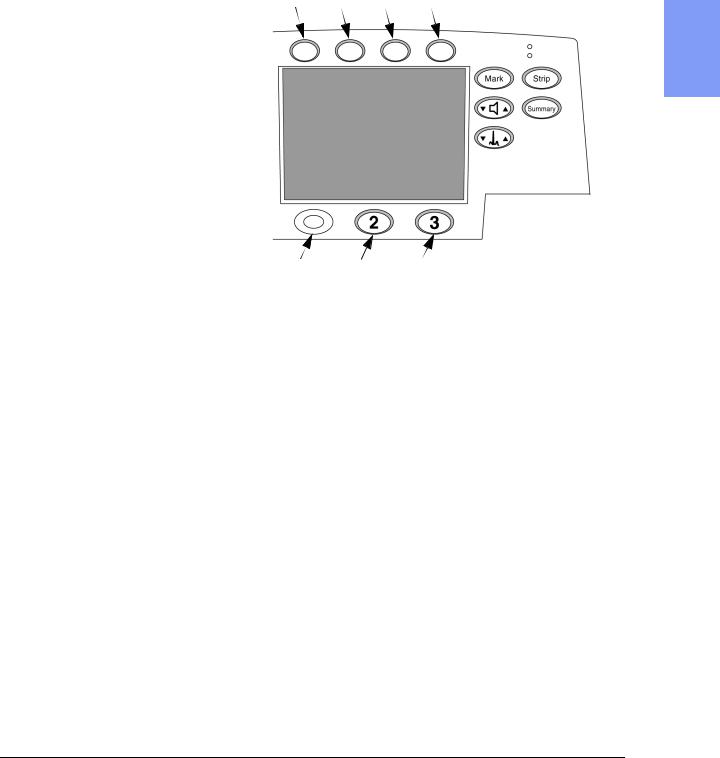
Press softkeys 4 and 5 at the same time, and hold them down while turning the power on. See Figure 2-1 for softkey numbering.
4.Select and manage Configuration choices.
zTo select a configuration, press the  and
and  softkeys to move up or down the list until the desired Settings item is highlighted. Then
press the ENTER softkey to access those settings.
zTo print out a strip with all the current configuration choices, select
Print All Settings and press ENTER .
zTo store the configuration settings on a Data Card, select Save Settings to Data Card and press ENTER . When prompted with Save Settings to Data Card? press SAVE .
zTo load configuration settings from a Data Card, select Load Settings from Data Card and press ENTER . When prompted with Load Settings from Data Card? press LOAD .
2-10 |
Performance Verification and Safety Tests |
Configuration and Diagnostic Modes
5.Exit Configuration Mode.
z To exit Configuration Mode, turn the unit off.
zWait 2 seconds. Remove the Data Card by pressing the black eject button and pulling the Data Card from the compartment.
Figure 2-1 Softkey Numbers
4 |
5 |
6 |
7 |
2
1 |
2 |
3 |
Diagnostic Mode
These instructions describe how to enter Diagnostic Mode. Once in Diagnostic Mode, you can do the following:
zPrint the System Log. See "System Log" on page 2-22.
zRun the Extended Self Test. See "Extended Self Test" on page 2-24.
zRun other Diagnostic Tests. See "Diagnostic Tests" on page 2-21.
1.Power off.
Make sure the unit’s power is off.
2.Enter Diagnostic Mode.
Press softkeys 4 and 6 at the same time, and hold them down while turning the Energy Select Switch to Manual On. (See Figure 2-1 for softkey numbering.)
3.Wait for the unit to initialize.
This may take several seconds. The unit is ready to proceed when the screen cursor responds to softkey inputs.
M4735A Service Manual |
2-11 |

The Language Support Tool
4.Select the desired test or function.
To select a test, press the  and
and  softkeys to move up or down the
list until the desired test is highlighted. Then press the ENTER softkey to start that test.
5.Exit Diagnostic Mode.
To exit Diagnostic Mode, turn the unit off.
The Language Support Tool
The Language Support Tool allows field service personnel to perform several tasks:1) to set the language of the Control PCA of the defibrillator; 2) to enable the SpO2 option; 3) to program in the serial number. These tasks need
to be performed under the following circumstances:
zThe Control PCA has been replaced.
The Control PCA contains all the operating software, configured for the installed hardware. It also contains the unit’s serial number, which was assigned and programmed during manufacturing.
The new Control PCA must be programmed to recognize the hardware installed in this unit, to contain that unit’s
serial number, and to set the language of the unit.
zThe unit has received an upgrade adding the SpO2 capability.
The added hardware will not be automatically recognized. The Control PCA must be programmed to recognize the new hardware installed.
zThe unit’s software is being updated.
Software upgrades are periodically released to resolve customer issues. The Language Support tool enables you to load new software onto the unit.
Using the Language Support Tool
1.Save the configuration to a Data Card.
a.Make sure the unit is powered off, and have either a fresh battery installed or the AC power cord plugged in.
b.Follow the instructions in "Configuration Mode" on page 2-10 to save the configuration to a Data Card.
2-12 |
Performance Verification and Safety Tests |

The Language Support Tool |
|
2. Activate the Language Support Tool |
|
a. Insert the Language Support Tool data card into the unit. |
|
b. Press softkey 7 and Mark at the same time, and hold them down while |
|
turning the Energy Select Switch to Manual On. (See Figure 2-1 for |
|
softkey numbering.) |
|
3. Follow the screen prompts. |
|
a. Press YES to continue. |
|
|
|
The message "Upgrade software found Proceed to Program?" is dis- |
2 |
played. |
b.Press Yes to set the unit’s language. Do not press any keys or touch the unit until the process is complete.
c.Select whether SpO2 hardware is installed or not as appropriate.
d.Program in the unit’s serial number.
zIf this is an SpO2 upgrade, the serial number should already be present. In this case, verify it against the factory-applied label on the bottom of the case.
zIf this is a Control PCA replacement, program in the serial number found on the factory-applied label on the bottom of the case using the softkeys as instructed on the screen. Be sure to program it in accurately, as the serial number is used for all repair history tracking.
e.Check all the displayed information carefully before proceeding.
zIf the displayed information is correct, follow the screen prompts to save the configuration.
zIf any of the information is incorrect, follow the prompts to NOT save the configuration, then start over by powering the unit off, then back on.
4.Turn off the power. Wait 2 seconds. Remove the Data Card by pressing the black eject button and pulling the card from the compartment.
5.Check the customer configuration.
a.Turn the unit back on and enter Configuration Mode (see "Configuration Mode" on page 2-10).
b.Print the configuration and check it against the printout from before the servicing began. Reset the configuration (or load it from a Data Card) as needed.
6.Verify performance.
Perform Performance Verification Testing as described in "Performance Verification and Safety Tests" starting on page 2-1.
M4735A Service Manual |
2-13 |

Performance Verification Tests
Performance Verification Tests
This section gives instructions for running Performance Verification tests on the M4735A. The tests are sequenced to check more basic functions first, and then build on that to check more complex functions. We recommend you perform these tests in this sequence. If desired, you can make copies of the Test Results Matrix (page 2-4) and use it to record results.
The Performance Verification tests include:
Section |
Page |
Visual Inspection |
2-15 |
Functional Checks |
2-17 |
Diagnostic Tests |
2-21 |
Safety Tests |
2-42 |
Battery Capacity Test |
2-46 |
2-14 |
Performance Verification and Safety Tests |
Loading...