


E1A

Réf: 755815
WORKSHOP
MANUAL
DIAGNOSTIC
SALES DIVISION
NETWORK TECHNICAL INFORMATION

CONTENTS
Page: 2
Reproductions or translations, even parrtial, are forbidden without the written consent of Peugeot Motocycles
CHARACTERISTICS ............................................................................................................................... 4
Machine markings: ................................................................................................................................. 4
Characteristics:........................................................................................................................................ 4
Frame:..................................................................................................................................................... 4
Capacities:............................................................................................................................................... 4
Dimensions:............................................................................................................................................. 4
Weight:.................................................................................................................................................... 4
Tyres:....................................................................................................................................................... 4
Engine markings:.................................................................................................................................... 4
SERVICE AND COMMISSIONING INSTRUCTIONS.......................................................................... 5
Check:...................................................................................................................................................... 5
Change:................................................................................................................................................... 5
Check and change:.................................................................................................................................. 5
Test machine:.......................................................................................................................................... 5
Battery commissioning and maintenance procedure............................................................................... 6
Commissioning:....................................................................................................................................... 6
Charging after prolonged immobilisation ............................................................................................... 7
Procedure:............................................................................................................................................... 7
Checks before handing over to the customer:.......................................................................................... 8
SPECIAL IMPORTANT POINTS............................................................................................................ 9
TIGHTENING TORQUES AND SPECIAL TOOLS............................................................................. 10
Tightening torques: ............................................................................................................................... 10
Frame:................................................................................................................................................... 10
Engine:.................................................................................................................................................. 10
Standard:............................................................................................................................................... 10
Special tools:.......................................................................................................................................... 10
TEP USER INSTRUCTIONS.................................................................................................................. 11
Presentation: ......................................................................................................................................... 11
Functioning:.......................................................................................................................................... 11
Apparatus functions:.............................................................................................................................. 11
Instructions for use: .............................................................................................................................. 11
Example of checking the charge with the TEP 96: ............................................................................... 12
In case of a fault on your TEP96:......................................................................................................... 12
Precautions:........................................................................................................................................... 12
TEP96 Version 2.0 logic diagram (the TEP96 screen order) :.............................................................. 13
Faults logic diagram: ............................................................................................................................ 14
Permanent defects:.............................................................................................................................. 14
Intermittent defects:............................................................................................................................ 14
Intermittent or permanent faults:......................................................................................................... 14
Actuators logic diagram:....................................................................................................................... 15
States logic diagram:............................................................................................................................. 16
Variables logic diagram: ....................................................................................................................... 17
6Volt BATTERY CELL DISCHARGE BENCH INSTRUCTIONS FOR USE.................................... 18
Characteristics:...................................................................................................................................... 18
Presentation: ......................................................................................................................................... 18
Protection:............................................................................................................................................. 18
Instructions for use: .............................................................................................................................. 18
Battery cell discharge:........................................................................................................................... 18
Precautions:........................................................................................................................................... 18
TROUBLESHOOTING LOGIC DIAGRAM......................................................................................... 19

CONTENTS
Page: 3
Reproductions or translations, even parrtial, are forbidden without the written consent of Peugeot Motocycles
Incident: the machine does not charge 100%:....................................................................................... 19
Incident: the machine does not charge:................................................................................................. 20
Incident: problems during the maintenance charge:............................................................................ 21
Incident: when the ignition is turned on, the machine does not start:.................................................. 23
Incident: impossible to enter immobiliser code: .................................................................................... 24
Incident: no drive from motor:.............................................................................................................. 25
Incident: motor traction fault: (motor does not run, lacks performance)............................................ 26
Incident: loss of range: ......................................................................................................................... 27
Range test:............................................................................................................................................. 28
ECU AND MOTOR DIAGNOSTIC........................................................................................................ 29
Incidents:............................................................................................................................................... 29
Causes: .................................................................................................................................................. 29
Troubleshooting:................................................................................................................................... 29
1/Fault diagnosis:................................................................................................................................ 29
2/To determine the faulty component:................................................................................................. 30
3/Checking the motor: ........................................................................................................................ 31
CHANGING THE ELECTRONIC CONTROL UNIT .......................................................................... 32
Important point: .................................................................................................................................... 32
Method for TEP 96 version 1.5. before July 1998:................................................................................ 32
Method for TEP 96 version 2.0. after July 1998:................................................................................... 32
BATTERY REPLACEMENT PROCEDURE (3 cells)........................................................................... 34
Important point: .................................................................................................................................... 34
Method for TEP 96 version 1.5. before July 1998:................................................................................ 34
Method for TEP 96 version 2.0. after July 1998:................................................................................... 34
CHARACTERISTICS
Page: 4
Reproductions or translations, even parrtial, are forbidden without the written consent of Peugeot Motocycles
CHARACTERISTICS
Machine markings:
Model code E1A
Characteristics:
Engine
Characteristics Direct current and
separate excitation
Energy recovery on
motor braking
Marque Leroy Somer or
Schabmüller
Max. power
output
2.8 kW
Engine speed 2100 rpm
Torque speed 2000 rpm
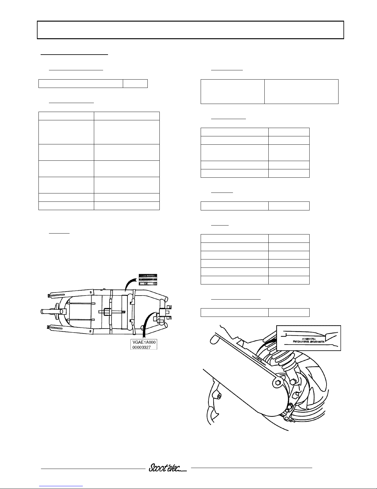
Frame:
1 Manufacturer’s plate
2 VIN number
Capacities:
Relay module 0.12 litres
Esso Gear oil (EZL 848)
P/N 753054
Dimensions:
Length 1755 mm
Width 695 mm
Height without rear
view mirror
1100 mm
Ground clearance 160 mm
Wheelbase 1300 mm
Weight:
Weight 115 kg
Tyres:
Front wheel 2.5"x10"
Front tyre 100/80x10
Front tyre pressure 2.5 bar
Rear wheel 2.5"x10"
Rear tyre 110/80x10
Rear tyre pressure 2.5 bar
Engine markings:
Engine type EA1
SERVICE AND COMMISSIONING PLAN
Page: 5
Reproductions or translations, even parrtial, are forbidden without the written consent of Peugeot Motocycles
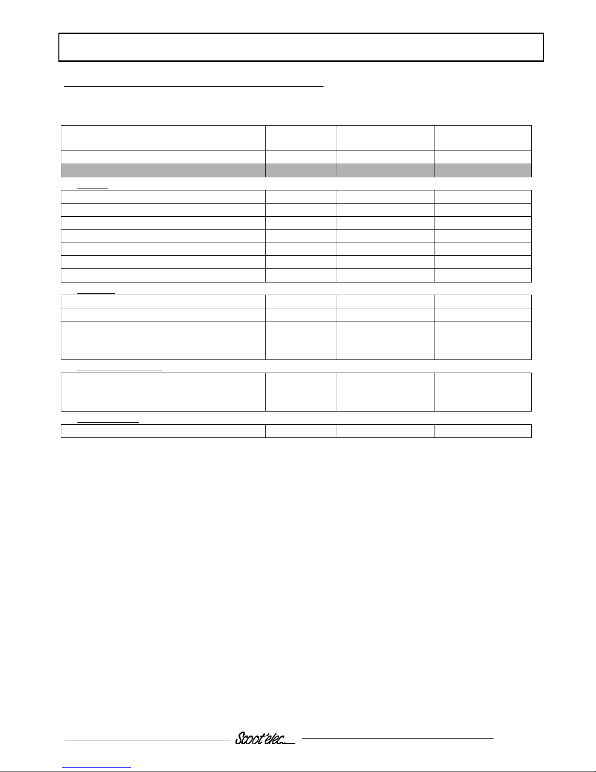
SERVICE AND COMMISSIONING INSTRUCTIONS
Heavy duty servicing is aimed at machines used under “harsh” conditions: door-to-door calls, intensive
urban use (courrier service)
Servicing operations 500 Kms
or 3 months
Every 5000 Kms
or months
Every 10000 Kms
Heavy duty service 500 Kms Every 2500 Kms Every 5000 Kms
Check:
Diagnostic readout X X X
Throttle control X X X
Functioning of electrical equipment X X X
Front and rear brake control X X X
Tyre pressures X
Tyre condition, pressure and wear X X
Tightness of nuts and bolts X X X
Change:
Front and rear brake lining X
Grease cam spindle X X
Drive belt 10000 km for
heavy duty
service
Check and change:
Motor brushes #
(depending on engine manufacturer)
10000 km for
heavy duty
service
X
Test machine:
On road X X X
# if necessary
SERVICE AND COMMISSIONING PLAN
Page: 6
Reproductions or translations, even parrtial, are forbidden without the written consent of Peugeot Motocycles
Battery commissioning and maintenance procedure
Remark: the maintenance procedure is identical to the commissioning procedure
Important:
It is essential to use distilled water supplied by PEUGEOT MOTOCYCLES under P/N: 973582
The use of distilled water from another sources will destroy the battery.
It is forbidden to pour in distilled water before the end of charging.
Commissioning:
Ensure you have 3 litres of PEUGEOT distilled water, P/N: 973582.
• Connect the charge cable to the 230 V – 10/16 A mains.
• The charge lamp comes on with a beep, the battery lamp flashes
• Press key “V” on the keypad there is a beep and hold until there is a second beep.
• Release the « V » key, a series of 3 beeps indicates the operation is to commence, the charge lamp
flashes.
• If it does not flash, repeat the operations more quickly.
The commissioning procedure has started and will take 10 to 15 minutes.
At the end of charging, the lamps stay on indicating that water may be added to the battery.
Note:
From this point on, you may leave the machine connected to the mains for a period of 72 hours. Beyond this
time, you will have to repeat the procedure from the start.
• Disconnect the charging cable, the lamps stay on. You now have a maximum of 30 minutes to
add water to the battery.
• Open the maintenance cover with a Torx screwdriver and slowly pour in the distilled water (P/N:
973582) until the water runs out of the overflow under the scooter.
• Close and tighten the maintenance cover, the lamps go off indicating the end of
commissioning.
• Wait for a minimum of 15 seconds before turning on the ignition.
SERVICE AND COMMISSIONING PLAN
Page: 7
Reproductions or translations, even parrtial, are forbidden without the written consent of Peugeot Motocycles
Charging after prolonged immobilisation
After not being used for a few months, the battery voltage may drop below 8 volts and it is impossible to put
the machine on charge.
In this case, the battery needs to be “woken up” by one or more connections / disconnections to and from the
mains socket.
Procedure:
1. Connect the charging connector to the mains.
Important:
• The charge lamp does not come on on the instrument panel.
• No beep on the multifunction keypad.
• The fan does not run.
This is normal.
Do not turn on the scooter lights.
Do not connect the TEP96.
2. Leave the connector connected 5 minutes to the mains
3. Disconnect the connector from the mains and reconnect it immediately
Repeat operations 2 and 3 until:
• The charge lamp comes on on the instrument panel.
• The multifunction key pad sounds a beep.
• The charger fan starts.
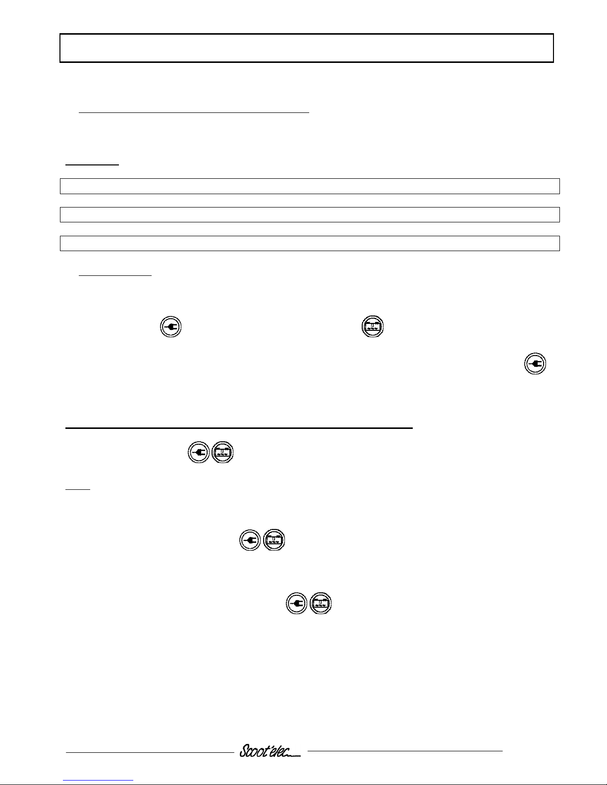
After 5 minutes charging (for ECU, electronic control unit, Software version 4.2.4, production prior to July
97)
Connect the TEP96 to the machine
The DISCHARGE value must be between 0 and 110 Ah
If the number of discharged Ah is over 110, use the TEP96 to carry out a “Exchange battery” procedure
Press the two buttons (A) for 3
seconds
OTHER FUNCTIONS
♦ Reading variables
♦ Memory battery
♦ Check in disjunct.
♦
All variables
♦ Large Amperemeter
♦ Large voltmeter
♦ Large speedometer
*VARIABLE (PAGE 2)*
Charge =0.0Ah
Discharge = 65.2Ah
Overcharg = 0.0Ah
OTHER FUNCTIONS
♦ Ιdentity UCE
♦ Ιdentity TEP
♦ SPECIAL FUNCTIONS
TO OPENING SPECIALS
FUNCTIONS
REQUEST AGREEMENT
PEUGEOT MOTOCYCLES
SPECIAL FUNCTIONS
♦ Exchange UCE
♦ Exchange battery
A

SERVICE AND COMMISSIONING PLAN
Page: 8
Reproductions or translations, even parrtial, are forbidden without the written consent of Peugeot Motocycles
Checks before handing over to the customer:
Check the wheel nuts are tight
Front wheel: 6 m.daN
Rear wheel 10 m.daN
Check all nuts and bolts are tight
Check brake adjustment and efficiency
Check the tyre pressures cold
Front wheel: 2.5 bar
Rear wheel 2.5 bar
Check operation of the lights, flashers, road and pedestrian horn, and brake light
Check operation of the various instrument panel lamps
Check the power reserve
Carry out a road test
SPECIAL IMPORTANT POINTS
Page: 9
Reproductions or translations, even parrtial, are forbidden without the written consent of Peugeot Motocycles
SPECIAL IMPORTANT POINTS
The scoot'elec is fitted with a coded immobiliser. This system prevents the machine from being started if the
user has not entered the secret code number. See manual.
Charging of the 3 Cadmium-Nickel batteries is by means of the on-board charger fitted with a 220V 10/16A
power connector with earth.
A partial charge may be carried out, and each charge of 10 minutes enables approximately 5 km to be
covered in ECO mode.
If the battery temperature is high, charging will only commence after the time it takes to cool down which is
controlled automatically by the charger and the ECU (which means that the charging time will be prolonged
by the same time).
The lamp will flash until the charge is triggered automatically. See manual.
TIGHTENING TORQUES AND SPECIAL TOOLS
Page: 10
Reproductions or translations, even parrtial, are forbidden without the written consent of Peugeot Motocycles
TIGHTENING TORQUES AND SPECIAL TOOLS
Tightening torques:
Lower body fairing 0.2m.daN
Footboard 0.4 m.daN
Speedo casing 0.1 m.daN
Saddle cover 0.6 m.daN
Front panel 0.1 m.daN
Rear panel 0.1 m.daN
Side fairings 0.1 m.daN
Rear mudguard * 0.8/0.1 m.daN
Mud flap * 0.6/0.8m.daN
Saddle locking plate 1.2 m.daN
Frame:
Front wheel spindle nut 6 m.daN
Rear wheel spindle nut 10 m.daN
arm to chassis mounting 4.6 m.daN
Shock absorber upper mount 4.3 m.daN
Shock absorber lower mount 2.5 m.daN
Steering locknut 7 m.daN
Engine:
Arm to engine mount 2.3 m.daN
Battery terminal nut 1.2 m.daN
Strap and 200 A fuse 1.2 m.daN
Engine to casing 1 m.daN
Drive pulley 4 m.daN
Driven pulley 4 m.daN
Standard:
Nut and bolt 5 mm diameter 0.5 m.daN
Nut and bolt 6mm diameter 1 m.daN
Nut and bolt 8mm diameter 2.2 m.daN
Nut and bolt 10mm diameter 3.5 m.daN
Nut and bolt 12mm diameter 5.5 m.daN
Special tools:
Description Item no..
Steering column spanner 754086
Discharge bench 753012
TEP 96 753011
Optional charger 5409
* depending on size of bolt
PEUGEOT ELECTRONIC TESTER (TEP 96) USER INSTRUCTIONS
Page: 11
Reproductions or translations, even parrtial, are forbidden without the written consent of Peugeot Motocycles
TEP USER INSTRUCTIONS
VERSION 1.5 AND 2.0
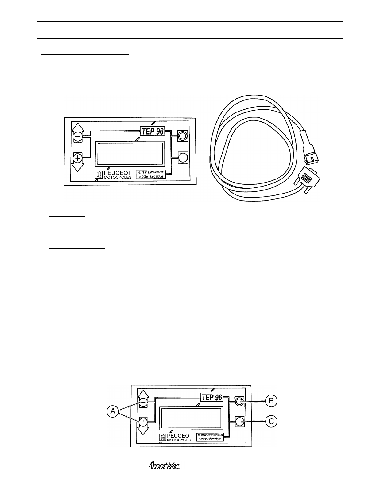
Presentation:
Unit with a display window, and connecting cable
Functioning:
Powered by the machine over the cable, the TEP 96 contains no batteries.
It dialogs with the ECU (Electronic Control Unit).
Apparatus functions:
Reads off the system functioning parameters
Reads off the fault codes recorded by the system
Checks the opening status of the maintenance hatch
Tests the functions (charger, keypad, ignition switch)
Runs the maintenance procedures to:
Change one or more of the traction battery cells
Change the ECU
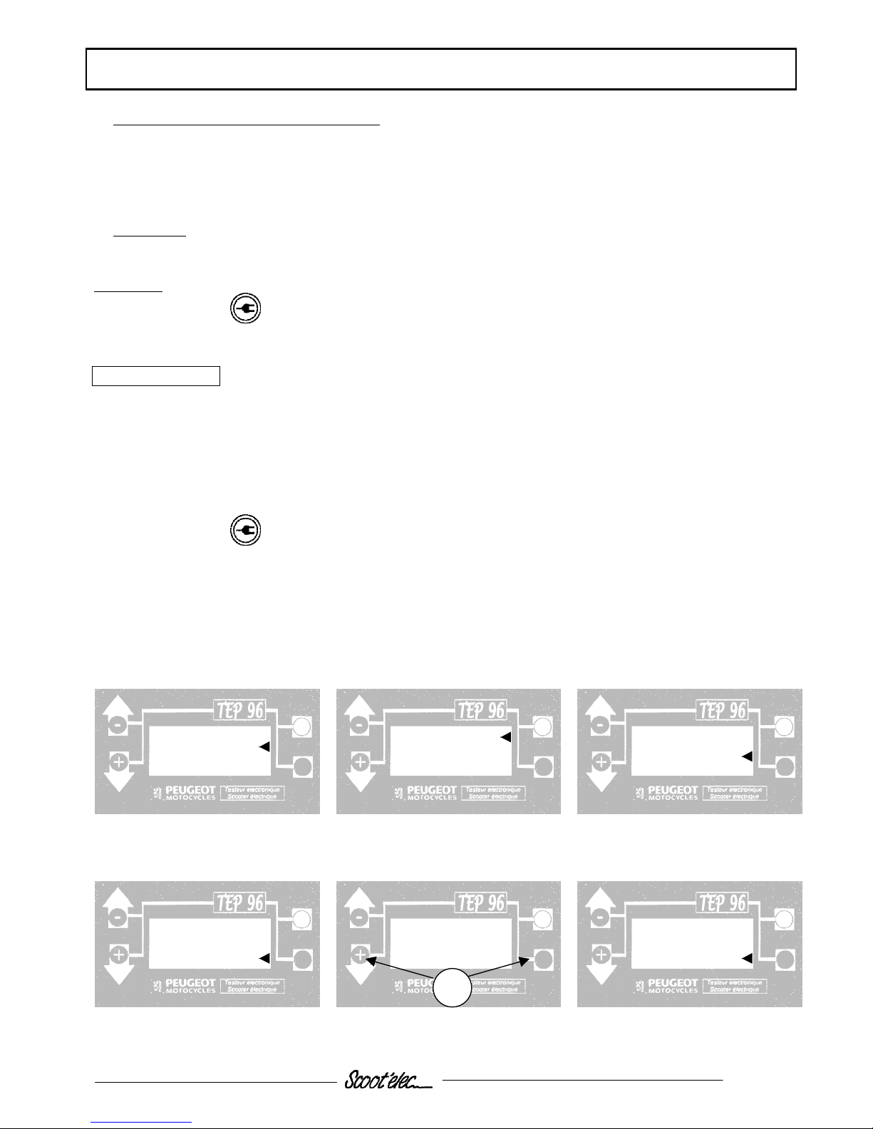
Instructions for use:
Connect the cable to the TEP 96 unit
Connect the other end of the cable to the diagnostic plug under the machine saddle
Read off the indications in the window
Buttons (A) are used to scroll through the menu or to change from one page to another
Button (B) is used to return to the menu or answer no
Button (C) is used to confirm or answer yes
 Loading...