


Sales division
Technical network leadership
WORKSHOP MANUAL

|
TABLE OF CONTENTS |
TABLE OF CONTENTS |
|
TABLE OF CONTENTS..................................................................................................................................... |
1 |
CHARACTERISTICS......................................................................................................................................... |
3 |
Engine........................................................................................................................................................ |
3 |
Capacities. ................................................................................................................................................. |
3 |
Chassis. ..................................................................................................................................................... |
4 |
Dimensions and weight.............................................................................................................................. |
4 |
Tyres. ......................................................................................................................................................... |
4 |
Brakes........................................................................................................................................................ |
5 |
SERVICE SCHEDULE AND COMMISSIONING............................................................................................... |
6 |
Check......................................................................................................................................................... |
6 |
Change ...................................................................................................................................................... |
6 |
Check and lubricate ................................................................................................................................... |
6 |
Test machine.............................................................................................................................................. |
6 |
Battery preparation (Except battery without maintenance)*. ..................................................................... |
6 |
Checks before handing over to the customer............................................................................................. |
7 |
SPECIAL IMPORTANT POINTS....................................................................................................................... |
8 |
Oil and fuel................................................................................................................................................. |
8 |
Starting up after overhauling the engine. ................................................................................................... |
8 |
TIGHTENING TORQUES .................................................................................................................................. |
9 |
Engine part. ............................................................................................................................................... |
9 |
Body panels. .............................................................................................................................................. |
9 |
Cycle part................................................................................................................................................. |
10 |
Standard. ................................................................................................................................................. |
10 |
INSTRUMENT PANEL .................................................................................................................................... |
11 |
Analog functions (hands). ........................................................................................................................ |
11 |
ELECTRICITY.................................................................................................................................................. |
12 |
Fuses and energy distribution.................................................................................................................. |
12 |
Location of components........................................................................................................................... |
12 |
BODY PANELS ............................................................................................................................................... |
13 |
Location of body components. ................................................................................................................. |
13 |
Body component sequence of disassembly. ............................................................................................ |
14 |
Removal of the storage compartment...................................................................................................... |
15 |
Removal of the grab handle. .................................................................................................................... |
15 |
Removal of the central cover panel.................................................................................... |
.............15 |
Removal of the lower side fairings. .......................................................................................................... |
16 |
Removal of the side fairings..................................................................................................................... |
16 |
Removal of the footboard......................................................................................................................... |
16 |
Removal of the taillignt............................................................................................................................. |
17 |


 1 Reproduction or translation, even partial, is forbidden without the written consent of Peugeot Motocycles

TABLE OF CONTENTS |
|
Removal of the splash guard. .................................................................................................................. |
17 |
Removal of the front top cover panel. ...................................................................................................... |
18 |
Removal of the front mudguard................................................................................................................ |
19 |
Removal of the front shield panel.................................................................................................... |
19 |
Removal of the rear shield panel. ............................................................................................................ |
20 |
Removal of the under body panel. .................................................................................................. |
20 |
Removal of a headlight bulb..................................................................................................................... |
21 |
Removal of a taillight bulb. ....................................................................................................................... |
21 |
Removal of a turnsignal light.................................................................................................................... |
22 |
WORKING ON THE ENGINE WITHOUT REMOVING THE ENGINE ............................................................. |
23 |
Removal of the air filter foam. .................................................................................................................. |
23 |
Removal of the transmission filter. ........................................................................................................... |
23 |
Removal of the fuel filter........................................................................................................................... |
23 |
Removal of the pulsair filter...................................................................................................................... |
24 |
Removal of the pulsair reed valve. ........................................................................................................... |
24 |
Removal of the spark plug. ...................................................................................................................... |
24 |
Removal of the carburettor....................................................................................................................... |
24 |
Installing the valve clearance. .................................................................................................................. |
25 |
Removal of the exhaust system. .............................................................................................................. |
25 |
Removal of the cylinder head................................................................................................................... |
26 |
Removal of the cylinder / piston. .............................................................................................................. |
26 |
MISCELLANEOUS OPERATIONS ................................................................................................................. |
27 |
Removal of the engine. ............................................................................................................................ |
27 |
Removal of the battery. ............................................................................................................................ |
27 |
Removal of the starter motor relay. .......................................................................................................... |
27 |
Removal of the ignition module (CDI). ..................................................................................................... |
27 |
Removal of the fuse. ................................................................................................................................ |
27 |
Removal of the regulator.......................................................................................................................... |
28 |
Removal of the choke resistor.................................................................................................................. |
28 |
Removal of the horn................................................................................................................................. |
28 |
Removal of the blinker unit....................................................................................................................... |
28 |
Removal of the ignition switch.................................................................................................................. |
28 |
Removal of the high tension coil. ............................................................................................................. |
28 |
Removal of the kickstand contact switch.................................................................................................. |
28 |
Removal of the fuel gauge. ...................................................................................................................... |
29 |
Removal of the tank. ................................................................................................................................ |
29 |
Removal of the front wheel. ..................................................................................................................... |
29 |
Removal of the rear wheel. ...................................................................................................................... |
30 |
Removal of the calliper............................................................................................................................. |
30 |
Removal of the brake pads. ..................................................................................................................... |
30 |
Removal of the fork. ................................................................................................................................. |
31 |
Replacing the bearings of the steering system........................................................................................ |
31 |
Steering system tightening method.......................................................................................................... |
32 |
2 

 Reproduction or translation, even partial, is forbidden without the written consent of Peugeot Motocycles

CHARACTERISTICS
CHARACTERISTICS
Engine.
|
V-clic 50cc. |
|
|
|
|
Type. |
4-stroke single-cylinder |
|
2 valves per cylinder with chain driven overhead camshaft. |
||
|
||
|
|
|
Cooling. |
Air. |
|
|
|
|
Bore x stroke. |
39.0 x 41.4 mm. |
|
|
|
|
Cubic capacity. |
49.58 cm3. |
|
|
|
|
Max. power output. |
2.0 kW à 7000 tr/min. |
|
|
|
|
Max. torque rating. |
6000 tr/min. |
|
|
|
|
Fuel supply. |
Carburettor. |
|
|
|
|
Lubrication. |
Trochoidal pump. |
|
|
|
|
Transmission. |
By 2 variable pulleys and V-type belt. |
|
|
|
|
Clutch. |
Centrifugal automatic. |
|
|
|
|
Spark plug. |
NGK CR 7HSA. |
|
|
|
|
Exhaust. |
Catalytic. |
|
|
|
|
Standards. |
Euro 2. |
|
|
|
|
Capacities. |
|
|
|
|
|
Fuel tank. |
6.3 l. |
|
|
|
|
Engine oil. |
0.8 l. |
|
|
|
|
Relay box. |
0.12 l. |
|
|
|
|
Fork. |
87cc by tube Esso Univis 46 or Agip H Lift 46. |
|
|
|


 3 Reproduction or translation, even partial, is forbidden without the written consent of Peugeot Motocycles

CHARACTERISTICS
Chassis.
Front suspension. |
Hydraulic telescopic fork. |
|
|
Travel. |
85 mm. |
|
|
Rear suspension. |
Combined spring and hydraulically-damped shock absorber. |
|
|
Travel. |
85 mm. |
|
|
Dimensions and weight.
Overall length. |
1660 mm. |
|
|
Width at handlebar. |
700 mm. |
|
|
Height (without rear-view |
1070 mm. |
mirrors). |
|
|
|
Wheelbase. |
1200 mm. |
|
|
Ground clearance. |
115 mm. |
|
|
Unladen weight. |
79 kg. |
|
|
Tyres.
Front wheel rim. |
10 inch aluminium alloy. |
|
|
Front tyre. |
3.50/10" |
|
|
Front tyre pressure. |
1.25 bars. |
|
|
Rear wheel rim. |
10 inch aluminium alloy. |
|
|
Rear tyre. |
3.50/10" |
|
|
Rear tyre pressure. |
1.75 bars. |
|
|
4 

 Reproduction or translation, even partial, is forbidden without the written consent of Peugeot Motocycles
CHARACTERISTICS
Brakes |
|
|
|
|
|
Front disc diameter and |
155 mm-4 mm. |
|
thickness |
||
|
||
|
|
|
Front brake caliper |
1 piston of 30.2 mm. |
|
|
|
|
Brake drum diameter. |
110 mm. |
|
|
|
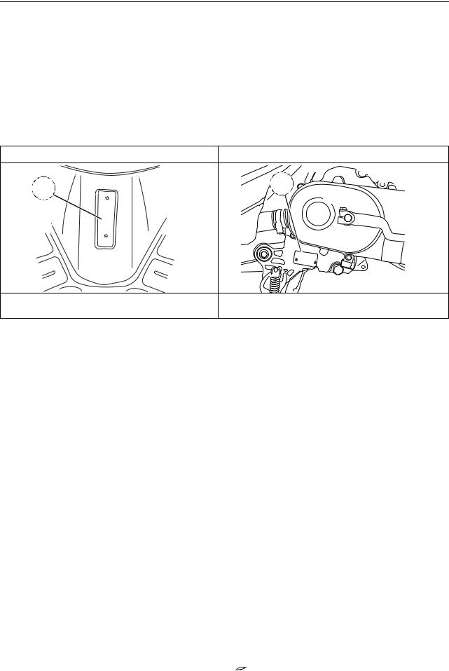
Chassis markings. |
Engine marking. |
1 |
2 |
|
|
xxxxxxxxxxxxxxxxx |
|
|
XXXXXX |
|
XXXXXXXX |
1. VIN (Rear shield). |
2. Engine number. |
- Manufacturer's plate (Right side).


 5 Reproduction or translation, even partial, is forbidden without the written consent of Peugeot Motocycles

SERVICE SCHEDULE AND COMMISSIONING
SERVICE SCHEDULE AND COMMISSIONING
Heavy duty servicing is for vehicles used under "harsh" conditions: door-to-door deliveries, intensive urban use (courier), short journeys with engine cold, dusty areas, ambient temperature over 30°C.
|
|
|
Every |
|
|
|
|
500 kms |
At |
5000 kms |
Every |
Every |
|
Service operations. |
or |
or |
||||
2000 kms. |
10000 kms. |
20000 kms. |
||||
|
1 months. |
12 months |
||||
|
|
|
. |
|
|
|
|
|
|
|
|
|
|
Heavy duty servicing. |
500 kms. |
At |
Every |
Every |
Every |
|
1000 kms. |
2500 kms. |
5000 kms. |
10000 kms. |
|||
|
|
|||||
|
|
|
|
|
|
|
Check |
|
|
|
|
|
|
|
|
|
|
|
|
|
Throttle cable play. |
C |
C |
C |
C |
C |
|
|
|
|
|
|
|
|
Steering column play. |
C |
C |
C |
C |
C |
|
|
|
|
|
|
|
|
Operation of electrical equipment. |
C |
C |
C |
C |
C |
|
|
|
|
|
|
|
|
Condition of the front brake hydraulic |
C |
C |
C |
C |
C |
|
control. |
||||||
|
|
|
|
|
||
|
|
|
|
|
|
|
Condition of petrol pipes. |
C |
C |
C |
C |
C |
|
|
|
|
|
|
|
|
Condition of oil pipes. |
C |
C |
C |
C |
C |
|
|
|
|
|
|
|
|
Tyre pressures. |
C |
C |
C |
C |
C |
|
|
|
|
|
|
|
|
Tyre condition, pressure and wear. |
C |
C |
C |
C |
C |
|
|
|
|
|
|
|
|
Condition of the front suspension. |
C |
C |
C |
C |
C |
|
|
|
|
|
|
|
|
Condition of the rear suspension. |
C |
C |
C |
C |
C |
|
|
|
|
|
|
|
|
Brake fluid level. |
C |
C |
C |
C |
C |
|
|
|
|
|
|
|
|
Battery electrolyte level*. |
C |
C |
C |
C |
C |
|
|
|
|
|
|
|
|
Tightness of nuts and bolts. |
C |
C |
C |
C |
C |
|
|
|
|
|
|
|
|
Change |
|
|
|
|
|
|
|
|
|
|
|
|
|
Spark plug. |
|
|
R |
R |
R |
|
|
|
|
|
|
|
|
Inlet silencer/air filter. |
|
|
|
|
R |
|
|
|
|
|
|
|
|
Front brake pads #. |
|
|
C |
C |
C |
|
|
|
|
|
|
|
|
Rear brake linings #. |
|
|
C |
C |
C |
|
|
|
|
|
|
|
|
Drive pulley bearings and guides #. |
|
|
C |
C |
C |
|
|
|
|
|
|
|
|
Transmission belt ##. |
|
|
R |
R |
R |
|
|
|
|
|
|
|
|
Engine oil (+ clean strainer). |
R |
R |
R |
R |
R |
|
|
|
|
|
|
|
|
Brake fluid. |
|
Once every 2 years |
|
|||
|
|
|
|
|
|
|
Relay box. |
|
|
|
R |
R |
|
|
|
|
|
|
|
|
Check and lubricate |
|
|
|
|
|
|
|
|
|
|
|
|
|
Kick starter mechanism. |
|
|
|
G |
G |
|
|
|
|
|
|
|
|
Drive pulley/Movable face. |
|
|
|
G |
G |
|
|
|
|
|
|
|
|
Test machine |
|
|
|
|
|
|
|
|
|
|
|
|
|
On road. |
C |
C |
C |
C |
C |
|
|
|
|
|
|
|
|
C : Check |
|
* Depending on equipment |
|
|||
N : Clean |
|
|
||||
R : Change |
|
# Change if necessary |
|
|||
G : Check and lubricate |
|
## Or once every 5 years |
|
|||
Battery preparation (Except battery without maintenance)*.
6 

 Reproduction or translation, even partial, is forbidden without the written consent of Peugeot Motocycles

SERVICE SCHEDULE AND COMMISSIONING
Remove the battery.
Remove the 6 filler caps and the vent plug.
Fill with electrolyte to the level marked "UPPER LEVEL".
The density shall be equal to 1.28 ± 0.01 Kg/L, that is to say a concentration of 32.3 to 34.7 %. Peugeot electrolyte P/N: 739733 1/2 l, 752741 5 l.
Leave the battery to stand for around half an hour.
Top up if necessary.
Charge the battery for at least 6 hours with a current of 0.5A.
Refit the battery and connect the vapour vent pipe.
Connect the terminal with the red wire to the battery + and the terminal with the black and white wire to the battery -.
Then, the battery level should be topped up if necessary, after fully charging, using distilled water only.
Checks before handing over to the customer.
Check the wheel nuts are tight. Check nuts and bolts are tight.
Check brake adjustment and efficiency. Check the tyre pressures cold.
Check operation of the lights, flashers, horn, and brake light. Check the different warning lights work.
Carry out a road test.


 7 Reproduction or translation, even partial, is forbidden without the written consent of Peugeot Motocycles

SPECIAL IMPORTANT POINTS
SPECIAL IMPORTANT POINTS
Oil and fuel.
This engine is designed to run on 95 or 98 unleaded fuel only.
Fuel pipes must absolutely be changed if there are any signs of wear, cracks, etc.
Petrol is highly inflammable, do not smoke in the working area and avoid proximity to flames or sparks. Work in a clear and well-ventilated area.
Before carrying out any work, leave the engine to cool for at least 2 hours.
Starting up after overhauling the engine.
When starting the engine hot or cold do not accelerate.
8 

 Reproduction or translation, even partial, is forbidden without the written consent of Peugeot Motocycles
|
TIGHTENING TORQUES |
|
|
TIGHTENING TORQUES |
|
Engine part. |
|
|
|
Cylinder head. |
1.8 m.daN |
|
|
Cylinder casings. |
1 m.daN |
|
|
Transmission cover. |
1 m.daN |
|
|
RH casing cover. |
1 m.daN |
|
|
Automatic tensioner. |
0.8/1 m.daN |
|
|
Starter motor. |
1 m.daN |
|
|
Rotor. |
5 m.daN |
|
|
Stator. |
0.8 m.daN |
|
|
Engine speed sensor. |
0.6 m.daN |
|
|
Drive pulley. |
5 m.daN |
|
|
Driven pulley. |
5 m.daN |
|
|
Spark plug. |
1.8 m.daN |
|
|
Inlet manifold. |
1 m.daN |
|
|
Body panels. |
|
|
|
Front mudguard. |
0.8 à 1.2 m.daN |
|
|
Handlebar cover. |
0.2 à 0.4 m.daN |
|
|
Front shield panels. |
0.2 à 0.4 m.daN |
|
|
Rear shield. |
0.2 à 0.4 m.daN |
|
|
Bottom panel. |
1 m.daN |
|
|
Floor panel. |
1 m.daN |
|
|
Saddle storage compartment. |
1 m.daN |
|
|
Rear panels. |
0.2 à 0.4 m.daN |
|
|
Grab handle. |
2.5 m.daN |
|
|
Rear mudguard. |
0.8 à 1 m.daN |
|
|


 9 Reproduction or translation, even partial, is forbidden without the written consent of Peugeot Motocycles

TIGHTENING TORQUES
Cycle part
Front wheel spindle. |
5.3 m.daN |
|
|
Rear wheel spindle nut. |
12 m.daN |
|
|
Linkrod to engine pivot. |
8 m.daN |
|
|
Linkrod to frame pivot. |
9.8 m.daN |
|
|
Shock absorber top mount. |
2.9 m.daN |
|
|
Shock absorber bottom mount. |
2.9 m.daN |
|
|
Exhaust to cylinder head mounting nut. |
1.8 m.daN |
|
|
Exhaust to casing mounting bolt. |
2.3 m.daN |
|
|
Upper cone. |
Hand tightened |
|
|
Steering locknut. |
3 m.daN |
|
|
Front brake caliper. |
2.6 m.daN |
|
|
Front brake disc. |
2.3 m.daN |
|
|
Handle bar. |
4.9 m.daN |
|
|
Standard.
Nut and bolt 5 mm diameter. |
0.4 m.daN |
|
|
Nut and bolt 6 mm diameter. |
0.9 m.daN |
|
|
Nut and bolt 8 mm diameter. |
1.2 m.daN |
|
|
Nut and bolt 10 mm diameter. |
2.6 m.daN |
|
|
Nut and bolt 12 mm diameter. |
3.9 m.daN |
|
|
10 

 Reproduction or translation, even partial, is forbidden without the written consent of Peugeot Motocycles
 Loading...