


WV-CW474AFE
Table of contents
 Loading...
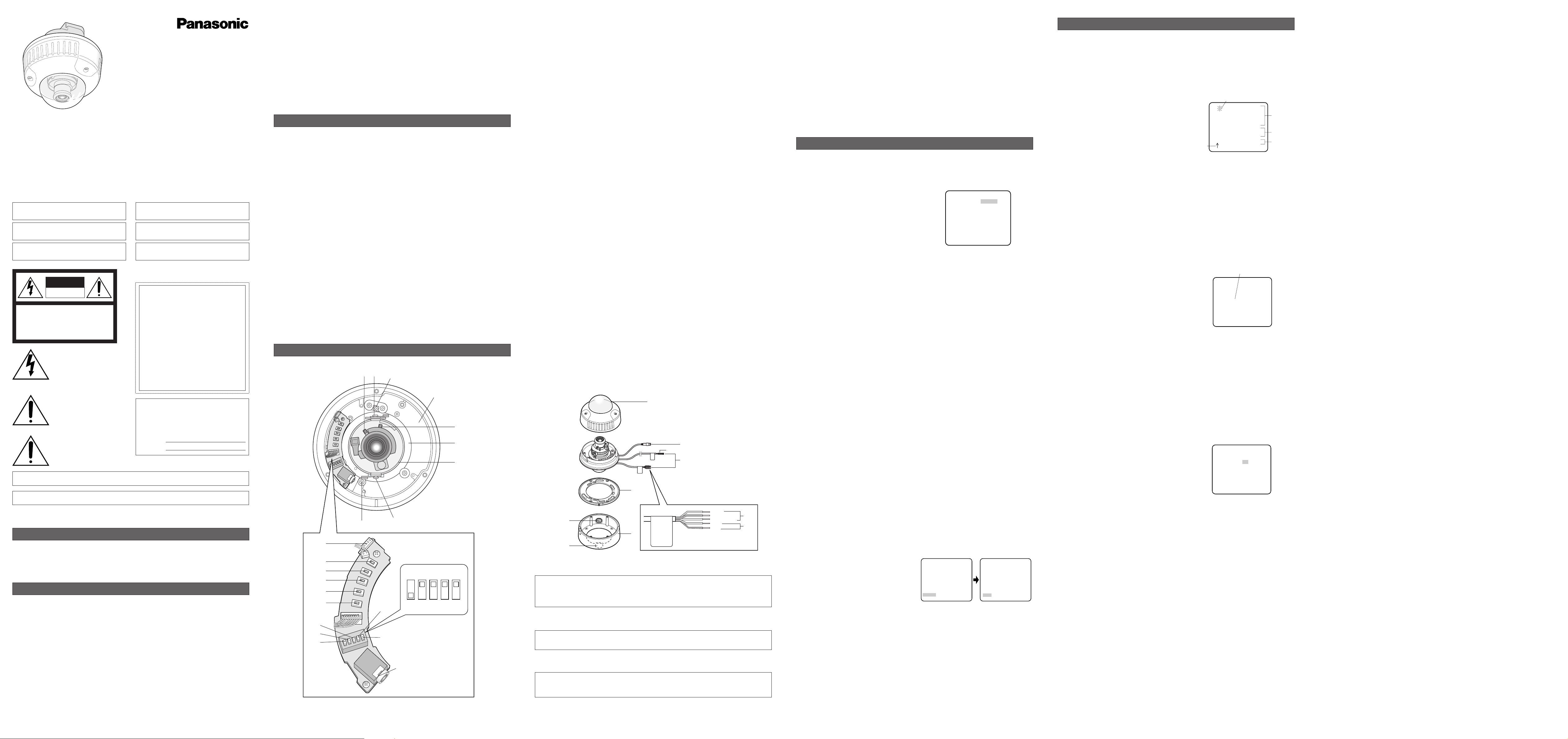
1. Camera Identification (CAMERA ID) Setting
You can use the camera identification (CAMERA ID) to assign a name to the camera. The camera ID
consists of up to 16 alphanumeric characters. The camera ID display can be switched on or off on
the monitor screen.
To edit the CAMERA ID
1. Move the cursor to CAMERA ID.
The factory default setting is OFF.
2. Press
I(S). The CAMERA ID menu appears.
The cursor on the letter “0” is highlighted.
3. Move the cursor to the character you want to edit
by pressing
I(L) / I(R) / I(U) / I(D).
4. After selecting the character, press
I(S). The
selected character appears in the editing area.
(The pointer in the editing area moves to the right
automatically at this moment.)
5. Repeat the steps above until all characters are
edited.
To enter a blank space in the CAMERA ID
Move the cursor to SPACE and press I(S).
To replace a specific character in the CAMERA ID
1. Move the cursor to the editing area by pressing I(D).
2. Move the pointer to the character to be replaced by pressing
I(L) or I(R). Then move the
cursor to the character area and select a new character.
3. Press
I(S) to determine the CAMERA ID.
To erase all characters in the editing area
Move the cursor to RESET and press I(S). All characters in the editing area disappear.
To determine the display position of the CAMERA ID
1. Move the cursor to POSI, and press I(S). The display at right appears and the CAMERA ID is
highlighted.
2. Move the CAMERA ID to the desired position by
pressing
I(L) / I(R) / I(U) / I(D).
3. Press
I(S) to fix the position of the CAMERA
ID. The mode returns to the previous CAMERA ID
menu.
Notes:
• The CAMERA ID stops at the edges of the
monitor screen.
• The CAMERA ID moves faster if any of
I(L) / I(R) / I(U) / I(D) is kept pressed
for a second or more.
2. Light Control Setting (ALC)
2-1. ALC Mode with SUPER-D2 ON
Super Dynamic2 Function (SUPER-D2)
The important object in a scene is usually placed in the center of the monitor screen. In the SUPER-
D2 mode, more photometric weight is given to the center of the screen (where the important object
is located) than to the edge of the screen (where a bright backlight would most likely be located).
The SUPER-D2 function eliminates interference by strong background lighting which makes the
camera picture dark, such as a spotlight.
1. Move the cursor to ALC and press
I(S). The ALC CONT menu appears.
2. Move the cursor to SUPER-D2 and select ON.
3. If you want to adjust the video output level,
move the "I" cursor for LEVEL. Adjust to the
desired level by pressing
I(L) or I(R).
(To be continued reverse page)
SETTING PROCEDURES
** ALC CONT **
BACK LIGHT COMP
SUPER-D2 ON
LEVEL ..I......
- +
RET END
WV-CW474A
Highlighted
0123456789
ABCDEFGHIJKLM
NOPQRSTUVWXYZ
().,'":;&#!?=
+-*/%$ДЬЦЖСЕ
SPACE
POSI RET END RESET
................
Character Cursor
Pointer
Character
Area
Command
Editing
Area
CAMERA ID menu
Caution:
Connect to 12 V DC (10.5 - 16 V) or 24 V AC (19.5 V-28 V) class 2 power supply only. Make
sure to connect the grounding lead to the GND terminal when the power is supplied from a
24 V AC power source.
q Panning table
Adjusts the panning angle of the camera.
w Pan lock screw
Fixes the panning position.
e Tilting lock screw
Fixes the tilting position.
r AZIMUTH (Angle adjuster)
Shoots in a straight-angle field of view when aiming at an object in a slanting direction even if
the tilt angle has been set.
t Zoom lock lever
Fixes the zoom position.
y Focus lock lever
Fixes the focus position.
u LEFT button (I) (L)
Moves the cursor to the left, selects the mode and adjusts some levels.
i RIGHT button (I) (R)
Moves the cursor to the right, selects the mode and adjusts some levels.
o UP button (I) (U)
Moves the cursor upward and selects items in the CAM SET UP menu.
!0 DOWN button (I) (D)
Moves the cursor downward and selects items in the CAM SET UP menu.
!1 SET button (I) (S)
Activates an item selected in the CAM SET UP menu.
!2 BW AUTO1 LEVEL switch (SW5)
Selects the illuminance level in LOW or HIGH mode for B/W. The factory default setting is HIGH.
!3 BW switch (SW4)
Switches to AUTO1 between colour and black-and-white picture in response to light input. The
factory default setting is OFF.
!4 AP gain switch (SW3)
Selects the aperture gain level to SHARP or SOFT. The factory default setting is SHARP.
!5 UPSIDE DOWN switch (SW2)
Turns the picture upside down by selecting ON. The factory default setting is OFF.
!6 Sync switch (SW1)
Switches internal sync (INT) mode or line-lock (LL) mode. The factory default setting is INT.
LL: Line-lock mode is driven by 24 V AC or 220 V - 240 V AC.
!7 Monitor output Jack (3.5 mm in Diam. mini jack)
Connects the LCD monitor and such devices with 3.5 mm in diam. 2-pole L-type plug for check-
ing images.
!8 Optional heater connector DC out
When an optional heater unit is installed in the camera, the harness exiting from the unit will be
connected to this.
@3
@2
@5
@1
!9
@0
Brown
Blue
Green/yellow
Black
Grey
!9-1
!9-2
!9-3
@4
!9-1Camera power cable for WV-CW474AFE (24 V AC 50 Hz or 12 V DC)
1. CAMERA SETUP MENU
This camera utilizes an on-screen user setup menu.
• Opening the Setup Menu
Press and hold down I(S) for 2 seconds or
more.
The CAM SET UP menu appears on the monitor as
shown at right.
Check the current settings on the menu.
Refer to the following sections for a detailed description of menu items. If you decide not to make
any changes after checking the current settings, move the cursor to END in the bottom line, and
press
I(S) to close the setup menu.
Note: If no button is pressed for 6 minutes while a setup menu is being displayed on the monitor
screen, it is automatically closed and the mode returns to the normal camera picture.
2. SETUP OPERATION
This camera utilizes an on-screen user setup menu (CAM SET UP). To set items on the CAM SET
UP menu, use the following buttons on the SW board.
Left Button
(I) (L): Moves the cursor to the left. Use this button to select or adjust the parame-
ters of the selected item. The parameter changes each time this button is
pressed.
Right Button
(I) (R): Moves the cursor to the right. Use this button to select or adjust the para-
meters of the selected item. The parameter changes each time this button
is pressed.
Up Button
(I) (U): Moves the cursor upwards. Use this button to select an item or adjust the
parameters.
Down Button
(I) (D): Moves the cursor downwards. Use this button to select an item or adjust
the parameters.
Set Button
(I) (S): Executes selections and displays a submenu for an item with the mark.
•To reset the parameter to the factory default setting, move the cursor to the parameter to be
reset and press
I(L) and I(R) simultaneously.
• To return to the previous menu or page, move the cursor to RET and press
I(S).
• To close the setup menu, move the cursor to END and press
I(S).
• All Reset Operation
All Reset allows you to reset all setup menu items to the factory default settings if you are unsure
about the correct settings. Proceed as follows:
(1) Make sure that the CAM SET UP menu is not displayed (a camera picture is displayed).
(2) While pressing both
I(L) and I(R), press I(S) for a few seconds. The message ALL
RESET momentarily appears on the monitor screen.
This resets all adjustments and parameters to the factory default settings except for the PIX
OFF setting.
• Editing the CAM SET UP Menu
Important Notice:
When SET UP DISABLE appears in the bottom line of the CAM SET UP menu, you cannot
change the currently active settings. This is to prevent accidental changing of the settings.
To edit the CAM SET UP menu (change settings), press
I(U) and I(D) or I(L) and I(R) to
move the cursor to SET UP DISABLE in the bottom line.
Press
I(S). SETUP DISABLE changes to
SETUP ENABLE. Move the cursor to DIP SW.
Press
I(S). DIP SW changes to MENU. Then
move the cursor to the item(s) you want to
change.
Notes:
•When DIP SW is selected for CAM SET UP
menu, five modes can be set with the DIP
switches.
• To operate the camera functions with the system controller, select MENU in the CAM SET UP
menu.
Important Notice:
When the setup menu is closed after changing the parameters in the menu, the new values are
stored in the EEPROM (Electrically Erasable and Programmable Read-Only Memory). These
values remain valid until new values are stored, even if the power of the camera is off.
↵
** CAM SET UP **
CAMERA ID OFF
ALC ALC
SHUTTER ---
AGC ON(HIGH)
SENS UP OFF
SYNC INT
WHITE BAL ATW1
MOTION DET OFF
DIP SW
END SET UP DISABLE
↵↵↵
** CAM SET UP **
CAMERA ID OFF
ALC ALC
SHUTTER ---
AGC ON(HIGH)
SENS UP OFF
SYNC INT
WHITE BAL ATW1
MOTION DET OFF
MENU
END SET UP ENABLE
↵↵
↵
↵
↵
SETUP
↵↵
↵
↵
** CAM SET UP **
CAMERA ID OFF
ALC ALC
SHUTTER ---
AGC ON(HIGH)
SENS UP OFF
SYNC INT
WHITE BAL ATW1
MOTION DET OFF
DIP SW
END SET UP DISABLE
1. The following functions are built in.
(1) Auto Light Control (ALC)
(2) The SUPER-D
2 function eliminates interference by strong background lighting which
makes the camera picture dark, such as a spotlight.
Dynamic range of 48 dB (Typ)
(3) Internal, Line-Locked, Multiplexed Vertical Drive (VD2) Sync
(4) Auto/Manual White Balance Function
(5) Electronic Shutter Function
2. Signal-to-noise ratio of 50 dB (Equivalent to AGC Off)
3. Minimum illumination of 2.0 lx (0.20 footcandle) (WIDE) (Colour mode)
Minimum illumination of 0.2 lx (0.02 footcandle) (WIDE) (Black-and-white mode)
Minimum illumination of 0.8 lx (0.08 footcandle) (WIDE) with the WV-CW2SE optional dome
cover (Colour mode)
Minimum illumination of 0.1 lx (0.01 footcandle) (WIDE) with the WV-CW2SE optional dome
cover (Black-and-white )
4. 480 lines of horizontal resolution (Colour normal mode)
510 lines of horizontal resolution (Colour High Resolution mode)
570 lines of horizontal resolution (Black-and-white mode)
5. High quality picture:
(a) 2H type vertical enhancer for greater picture sharpness
(b) Chroma averaging circuit for better colour signal-to-noise ratio
(c) Minimum of aliasing on fine objects
(d) Expanded dynamic range by use of knee circuit
(e) Highlight aperture correction for greater picture detail of bright objects
6. Selectable electronic sensitivity enhancing modes including AUTO, MANUAL and OFF
7. Built-in Digital Motion Detector
8. Auto black-and-white mode enables the camera to switch between colour and black-and-white
picture in response to Light input.
9. Electronic zoom function magnifies a scene 2-fold and changes the angle of view.
FEATURES
1. Do not attempt to disassemble the camera.
To prevent electric shock, do not remove screws or covers.
There are no user-serviceable parts inside. Ask qualified service personnel for servicing.
2. Handle the camera with care.
Do not abuse the camera. Avoid striking, shaking, etc. The camera could be damaged by
improper handling or storage.
3. The installation should be made by qualified service personnel or system installers.
4. Do not use strong or abrasive detergents when cleaning the camera body.
Use a dry cloth to clean the camera when dirty. When the dirt is hard to remove, use a mild
detergent and wipe gently. Then wipe off the remaining detergent with a dry cloth.
5. Clean the lens with care.
Do not clean the lens with strong or abrasive detergents. Use lens tissue or a cotton tipped
applicator and ethanol.
PRECAUTIONS
Before attempting to connect or operate this product,
please read these instructions carefully and save this manual for future use.
MAJOR OPERATING CONTROLS AND THEIR FUNCTIONS
N0304-0 3TR002452AAA Printed in Japan
Panasonic's WV-CW474AF/CW470AS series colour digital camera introduces a new level of high
picture quality and high resolution through the use of a 1/3-inch interline transfer CCD image sensor
having 752 horizontal pixels (picture elements), and digital signal processing LSIs. This model
offers cutting-edge technology for advanced video surveillance.
PREFACE
Colour CCTV Cameras
Operating Instructions
Remove: Transport protection screw (Red)
Space for heater unit
t
q
r
w
Remove: Transport protection screw (Red)
L
EFT
U
P
D
OWN
SET
R
IGHT
LOW
HIGH
OFF
AUTO1
SHARP
SOFT
OFF
ON
INT
LL
u
i
o
!0
!1
!2
!3
!4
!5
!6
!7
!8
ye
Model Nos. WV-CW474AFE
WV-CW470AS
!9-3Camera power cable for WV-CW470AS (220 V - 240 V AC 50 Hz)
Caution:
Connect to 24 V AC (19.5 V-28 V) class 2 power supply only.
@0 Video output cable with BNC connector
Connects with the video connector of the monitor.
Caution:
Before attempting to connect or operate this
product, please read the marking on the top.
The serial number of this product may be found on
the top of the unit.
You should note the serial number of this unit in the
space provided and retain this instruction as a per-
manent record of your purchase to aid identification
in the event of theft.
Model No.
Serial No.
CAUTION: TO REDUCE THE RISK OF ELECTRIC SHOCK,
DO NOT REMOVE COVER (OR BACK).
NO USER-SERVICEABLE PARTS INSIDE. REFER SER-
VICING TO QUALIFIED SERVICE PERSONNEL.
CAUTION
RISK OF ELECTRIC
SHOCK DO NOT OPEN
FOR YOUR SAFETY PLEASE READ THE FOLLOWING TEXT
CAREFULLY.
WARNING: This apparatus must be earthed.
IMPORTANT
The wires in this mains lead are coloured in accordance with the
following code.
Green-and-yellow: Earth
Blue: Neutral
Brown: Live
As the colours of the wire in the mains lead of this appliance
may not correspond with the coloured markings identifying the ter-
minals in your plug, proceed as follows.
The wire which is coloured
green-and-yellow must be con-
nected to the terminal in the plug which is marked with the letter
E
or by the earth symbol I or coloured green or green-and-yellow.
The wire which is coloured blue must be connected to the ter-
minal in the plug which is marked with the letter
N or coloured
black.
The wire which is coloured brown must be connected to the
terminal in the plug which is marked with the letter
L or coloured
red.
The exclamation point within an
equilateral triangle is intended to
alert the user to the presence of
important operating and mainte-
nance (servicing) instructions in the
literature accompanying the appli-
ance.
The lightning flash with arrowhead
symbol, within an equilateral trian-
gle, is interned to alert the user to
the presence of uninsulated "dan-
gerous voltage" within the product's
enclosure that may be of sufficient
magnitude to constitute a risk of
electric shock to persons.
Vi deklarerar härmed värt fulla ansvar för att den produkt till
vilken denna deklaration hänvisar är i överensstämmelse med
standarddokument, eller andra normativa dokument som
framstölls i Direktiv 73/23/EEC och 89/ 336/EEC.
Ilmoitamme yksinomaisella vastuullamme, että tuote, jota tämä
ilmoitus koskee, noudattaa seuraavia standardeja tai muita
ohjeellisia asiakirjoja, jotka noudattavat direktiivien 73/23/EEC
ia 89/336/EEC. säädöksiä.
We declare under our sole responsibility that the product to
which this declaration relates is in conformity with the stan-
dards or other normative documents following the provisions of
Directives EEC/73/23 and EEC/89/336.
Wij verklaren als enige aansprakelijke, dat het product waarop
deze verklaring betrekking heeft, voldoet aan de volgende
normen of andere normatiefve dokumenten, overeenkomstig
de bepalingen van Richtlijnen 73/23/ EEC en 89/336/EEC.
Vi erklærer os eneansvarlige for, at dette produkt, som denne
deklaration omhandler, er i overensstemmelse med den
følgende standarder eller andre normative dokumenter i følge
bestemmelserne i direktivene 73/23/ EEC og 89/336/EEC.
Vi erklærer oss alene ansvarlige for at produktet som denne
erklæringen gjelder for, er i overensstemmelse med følgende
normer eller andre normgivende dokumenter som fælger
bestemmelsene i direktiven 73/23/ EEC og 89/336/EEC.
Turn the power off at the mains to
disconnect the main power for all
unit.
WARNING: All work related to the installation of this product should be made by qualified service personnel or sys-
tem installers.
CAUTION: An ALL-POLE MAINS SWITCH with a contact separation of at least 3 mm in each pole shall be incorpo-
rated in the electrical installation of the building.
6. Never face the camera towards the sun.
Do not aim the camera at bright objects. Whether the camera is in use or not, never aim it at the
sun or other extremely bright objects. Otherwise, blooming or smear may be caused.
7. Do not operate the camera beyond the specified temperature, humidity or power source
ratings.
Use the camera at temperatures within –10 °C to +50 °C (–14°F - 122°F), and humidity below 90
%. The input power source for WV-CW474AFE is 24 V AC 50 Hz or 12 V DC and for WV-
CW470AS is 220 V - 240 V AC 50 Hz.
8. Turn the circuit breaker off which supplies the camera with the power when abnormal
conditions are encountered.
!99-2Power cable for heater unit WV-CW3HE (24 V AC 50 Hz) (applicable only to WV-
CW474AFE)
Caution:
Connect to 220 V - 240 V AC 50 Hz. The optional heater unit operates on 24 V AC that has
been supplied through the camera.
@1111 Dome cover
@2 Camera mounting bracket
The WV-CW470AS is supplied with a mounting bracket for ceiling installation.
@3 Camera attachment
@4 Cable access hole
@5 Sideway cable exit
The model shown is WV-CW474AFE.
Loading...