


 Loading...
Panasonic Telephone Systems
Panasonic KX-TDA50 KX-TDA100 KX-TDA200 KX-TDA600
www.voicesonic.com
Phone: 877-289-2829
Hybrid IP-PBX
PC Programming Manual
Panasonic KX-TDA50, KXTDA50, TDA50, KX-TDA100, KXTDA100, TDA100, KX-TDA200, KXTDA200, TDA200, KX-TDA600, KXTDA600, TDA600
Thank you for purchasing a Panasonic Hybrid IP-PBX.
Please read this manual carefully before using this product and save this manual for future use.
KX-TDA50: PSMPR Software File Version 4.0000 or later KX-TDA100/KX-TDA200: PMPR Software File Version 5.0000 or later KX-TDA600: PLMPR Software File Version 5.0000 or later
Document Version: 2008-03

Introduction
About this Programming Manual
The PC Programming Manual is designed to serve as a system programming reference for the Panasonic Hybrid IP-PBX. It explains how to program this PBX using the Maintenance Console software.
The PC Programming Manual is divided into the following sections:
Section 1, Overview
Provides an overview of programming the PBX.
Section 2, Maintenance Console Operating Instructions
Serves as reference operating instructions when using the Maintenance Console software to program the PBX.
Section 3, Appendix
Provides a list of all related PC programming items for each feature as Feature Programming References.
References Found in the PC Programming Manual
Programming Manual References
Related sections of the PC Programming Manual are listed for your reference.
Feature Manual References
The Feature Manual explains what the PBX can do, as well as how to obtain the most of its many features and facilities. Sections from the Feature Manual are listed throughout this manual for your reference.
Installation Manual References
The Installation Manual provides instructions detailing the installation and maintenance of the PBX. Sections from the Installation Manual are listed throughout this manual for your reference.
Links to Other Pages and Manuals
If you are viewing this manual with a PC, certain items are linked to different sections of this and other PBX manuals. Click on a link to jump to that section.
Linked items include:
•Installation Manual References
•PC Programming Manual References
•Feature Manual References
WARNING
Unplug the PBX from the AC outlet if it emits smoke, an abnormal smell or makes unusual noise. These conditions can cause fire or electric shock. Confirm that smoke has stopped and contact an authorized Panasonic Factory Service Center.
2 PC Programming Manual

Trademarks
•Microsoft, Windows, and Windows Vista are either registered trademarks or trademarks of Microsoft Corporation in the United States and/or other countries.
•Intel and Celeron are trademarks or registered trademarks of Intel Corporation in the United States and other countries.
•All other trademarks identified herein are the property of their respective owners.
•Microsoft product screen shot(s) reprinted with permission from Microsoft Corporation.
NOTES
•The contents of this manual apply to PBXs with a certain software version, as indicated on the cover of this manual. To confirm the software version of your PBX, see How do I confirm the software version of the PBX or installed cards? in 2.7.1 Frequently Asked Questions (FAQ).
•Some optional service cards, PTs, and features are not available in some areas. Additionally, some optional service cards and features are not available for some PBX models. Please consult your certified Panasonic dealer for more information.
•Product specifications are subject to change without notice.
In some cases, additional information, including updates to this and other manuals, is included in the Maintenance Console's Information before programming. Install the latest version of Maintenance Console to view this information.
PC Programming Manual |
3 |
|
|

Table of Contents |
|
|
1 Overview.................................................................................................. |
9 |
|
1.1 |
Introduction .................................................................................................................... |
10 |
1.1.1 |
Introduction ...................................................................................................................... |
10 |
1.1.2 |
Entering Characters ......................................................................................................... |
10 |
1.2 |
PC Programming............................................................................................................ |
12 |
1.2.1 |
Installing and Starting the Maintenance Console............................................................. |
12 |
1.2.2 |
Password Security............................................................................................................ |
15 |
2 Maintenance Console Operating Instructions ................................... |
17 |
|
2.1 |
Introduction .................................................................................................................... |
18 |
2.1.1 |
Starting Maintenance Console and Software Modes ....................................................... |
18 |
2.1.2 |
Access Levels .................................................................................................................. |
20 |
2.1.3 |
Software Interface ............................................................................................................ |
24 |
2.1.4 |
Card Status ...................................................................................................................... |
27 |
2.1.5 |
Display Options ................................................................................................................ |
28 |
2.1.6 |
Extension Number Setting ............................................................................................... |
28 |
2.2 |
Start Menu....................................................................................................................... |
30 |
2.2.1 |
Start Menu—New............................................................................................................. |
30 |
2.2.2 |
Start Menu—Open ........................................................................................................... |
30 |
2.2.3 |
Start Menu—Connect—RS-232C .................................................................................... |
31 |
2.2.4 |
Start Menu—Connect—USB ........................................................................................... |
31 |
2.2.5 |
Start Menu—Connect—LAN ............................................................................................ |
32 |
2.2.6 |
Start Menu—Connect—Modem ....................................................................................... |
33 |
2.2.7 |
Start Menu—Connect—Profile Setup .............................................................................. |
34 |
2.3 |
File ................................................................................................................................... |
35 |
2.3.1 |
File—Close....................................................................................................................... |
35 |
2.3.2 |
File—Save........................................................................................................................ |
35 |
2.3.3 |
File—Save As................................................................................................................... |
35 |
2.3.4 |
File—Exit.......................................................................................................................... |
35 |
2.4 |
Disconnect...................................................................................................................... |
37 |
2.4.1 |
Disconnect—Disconnect .................................................................................................. |
37 |
2.5 |
Tool.................................................................................................................................. |
38 |
2.5.1 |
Tool—SD memory backup ............................................................................................... |
38 |
2.5.2 |
Tool—NDSS Link Data Clear ........................................................................................... |
38 |
2.5.3 |
Tool—DXDP All OUS ....................................................................................................... |
38 |
2.5.4 |
Tool—Simplified Voice Message—Delete All Recording.................................................. |
38 |
2.5.5 |
Tool—Simplified Voice Message—Check Current Usage ................................................ |
39 |
2.5.6 |
Tool—Extension List View ................................................................................................ |
39 |
2.5.7 |
Tool—Import..................................................................................................................... |
39 |
2.5.8 |
Tool—Export .................................................................................................................... |
43 |
2.5.9 |
Tool—Screen Customize—User Level/Administrator Level.............................................. |
43 |
2.6 |
Utility ............................................................................................................................... |
44 |
2.6.1 |
Utility—Diagnosis ............................................................................................................. |
44 |
2.6.2 |
Utility—File Transfer PC to PBX (SD Card)...................................................................... |
48 |
2.6.3 |
Utility—File Transfer PBX (SD Card) to PC...................................................................... |
52 |
2.6.4 |
Utility—SD Card File View and Load ............................................................................... |
53 |
2.6.5 |
Utility—SD Card File Delete............................................................................................. |
54 |
4 PC Programming Manual

2.6.6 |
Utility—Message File Transfer PC to PBX ....................................................................... |
54 |
2.6.7 |
Utility—Message File Transfer PBX to PC ....................................................................... |
55 |
2.6.8 |
Utility—Error Log.............................................................................................................. |
55 |
2.6.9 |
Utility—T1 Signaling Bit Monitor (KX-TDA100/KX-TDA200/KX-TDA600 only) ................ |
57 |
2.6.10 |
Utility—T1 Line Trace (KX-TDA100/KX-TDA200/KX-TDA600 only)................................. |
58 |
2.6.11 |
Utility—ISDN/QSIG Protocol Trace .................................................................................. |
58 |
2.6.12 |
Utility—Digital Trunk Error Report (KX-TDA100/KX-TDA200/KX-TDA600 only).............. |
59 |
2.6.13 |
Utility—IP Extension Statistical Information ..................................................................... |
60 |
2.6.14 |
Utility—CS Information..................................................................................................... |
60 |
2.6.15 |
Utility—PS Information..................................................................................................... |
61 |
2.6.16 |
Utility—Timed Update (KX-TDA100/KX-TDA200/KX-TDA600 only)................................ |
62 |
2.6.17 |
Utility—System Reset—Reset by the Command ............................................................. |
63 |
2.6.18 |
Utility—Flash ROM ID Information ................................................................................... |
65 |
2.7 |
Help ................................................................................................................................. |
66 |
2.7.1 |
Frequently Asked Questions (FAQ).................................................................................. |
66 |
2.8 |
[1] Configuration ............................................................................................................ |
77 |
2.8.1 |
[1-1] Slot........................................................................................................................... |
77 |
2.8.2 |
[1-1] Slot—Summary ....................................................................................................... |
81 |
2.8.3 |
[1-1] Slot—Card Property - MPR ..................................................................................... |
85 |
2.8.4 |
[1-1] Slot—Card Property - Extension Type..................................................................... |
86 |
2.8.5 |
[1-1] Slot—Port Property - Extension Port ....................................................................... |
91 |
2.8.6 |
[1-1] Slot—Port Property - Extension Port—Connection Command.............................. |
100 |
2.8.7 |
[1-1] Slot—Port Property - Extension Port—Port Type View.......................................... |
101 |
2.8.8 |
[1-1] Slot—Port Property - CSI/F Port (KX-TDA100/KX-TDA200/KX-TDA600 only)...... |
102 |
2.8.9[1-1] Slot—Port Property - CSI/F Port—Connection Command (KX-TDA100/KX-TDA200/
KX-TDA600 only) ........................................................................................................... |
104 |
2.8.10 [1-1] Slot—Card Property - LCO type ............................................................................ |
105 |
2.8.11 [1-1] Slot—Port Property - LCO Port.............................................................................. |
114 |
2.8.12 [1-1] Slot—Port Property - LCO Port—Connection Command ...................................... |
120 |
2.8.13 [1-1] Slot—Card Property - PRI type (KX-TDA100/KX-TDA200/KX-TDA600 only) ....... |
121 |
2.8.14 [1-1] Slot—Port Property - PRI Port (KX-TDA100/KX-TDA200/KX-TDA600 only)......... |
136 |
2.8.15[1-1] Slot—Port Property - PRI Port—Connection Command (KX-TDA100/KX-TDA200/KX-
|
TDA600 only)158 |
|
2.8.16 |
[1-1] Slot—Card Property - T1 type (KX-TDA100/KX-TDA200/KX-TDA600 only) ......... |
159 |
2.8.17 |
[1-1] Slot—Port Property - T1 Port (KX-TDA100/KX-TDA200/KX-TDA600 only)........... |
170 |
2.8.18[1-1] Slot—Port Property - T1 Port—Connection Command (KX-TDA100/KX-TDA200/KX-
TDA600 only) ................................................................................................................. |
179 |
2.8.19 [1-1] Slot—Card Property - IP Gateway......................................................................... |
180 |
2.8.20 [1-1] Slot—Port Property - IP-GW Port .......................................................................... |
182 |
2.8.21 [1-1] Slot—Port Property - IP-GW Port—Connection Command................................... |
184 |
2.8.22 [1-1] Slot—Card Property - IP Extension ....................................................................... |
185 |
2.8.23 [1-1] Slot—Card Property - IP Extension—Common Settings ....................................... |
189 |
2.8.24 [1-1] Slot—Port Property - IP-Extension Port................................................................. |
191 |
2.8.25 [1-1] Slot—OPB3 Card Property (KX-TDA100/KX-TDA200/KX-TDA600 only).............. |
197 |
2.8.26[1-1] Slot—OPB3 Card Property—Card Command (KX-TDA100/KX-TDA200/KX-TDA600
|
only) ............................................................................................................................... |
202 |
2.8.27 [1-1] Slot—OPB3 Option Card Setup (KX-TDA100/KX-TDA200/KX-TDA600 only) ...... |
204 |
|
2.8.28 [1-1] Slot—Card Property - CTILINK (KX-TDA100/KX-TDA200/KX-TDA600 only) ....... |
206 |
|
2.8.29 |
[1-1] Slot—Card Property - DPH type (KX-TDA50 only)................................................ |
208 |
2.8.30 |
[1-1] Slot—Card Property - DPH type—Connection Command (KX-TDA50 only) ........ |
211 |
PC Programming Manual |
5 |
|
|

2.8.31 |
[1-2] Portable Station ..................................................................................................... |
212 |
2.8.32 |
[1-3] Option .................................................................................................................... |
215 |
2.8.33 |
[1-4] Clock Priority (KX-TDA100/KX-TDA200/KX-TDA600) ........................................... |
218 |
2.9 |
[2] System ..................................................................................................................... |
219 |
2.9.1 |
[2-1] Date & Time/Daylight Saving ................................................................................. |
219 |
2.9.2 |
[2-1] Date & Time/Daylight Saving—Date & Time Setting ............................................. |
220 |
2.9.3 |
[2-2] Operator & BGM .................................................................................................... |
221 |
2.9.4 |
[2-3] Timers & Counters ................................................................................................. |
223 |
2.9.5 |
[2-4] Week Table ............................................................................................................ |
245 |
2.9.6 |
[2-4] Week Table—Time Setting..................................................................................... |
245 |
2.9.7 |
[2-5] Holiday Table.......................................................................................................... |
248 |
2.9.8 |
[2-6-1] Numbering Plan—Main....................................................................................... |
250 |
2.9.9 |
[2-6-2] Numbering Plan—Quick Dial .............................................................................. |
279 |
2.9.10 |
[2-6-3] Numbering Plan—B/NA DND Call Feature......................................................... |
281 |
2.9.11 |
[2-7-1] Class of Service—COS Settings ........................................................................ |
285 |
2.9.12 |
[2-7-2] Class of Service—External Call Block ................................................................ |
299 |
2.9.13 |
[2-7-3] Class of Service—Internal Call Block ................................................................. |
300 |
2.9.14 |
[2-8-1] Ring Tone Patterns—Call from CO ..................................................................... |
301 |
2.9.15 |
[2-8-2] Ring Tone Patterns—Call from Doorphone ........................................................ |
301 |
2.9.16 |
[2-8-3] Ring Tone Patterns—Call from Others ............................................................... |
302 |
2.9.17 |
[2-9] System Options...................................................................................................... |
304 |
2.9.18 |
[2-10] Extension CID Settings ........................................................................................ |
334 |
2.9.19 |
[2-11-1] Audio Gain—Paging/MOH ................................................................................ |
339 |
2.9.20 |
[2-11-2] Audio Gain—Card............................................................................................. |
342 |
2.10 |
[3] Group ....................................................................................................................... |
343 |
2.10.1 |
[3-1-1] Trunk Group—TRG Settings............................................................................... |
343 |
2.10.2 |
[3-1-2] Trunk Group—Local Access Priority ................................................................... |
350 |
2.10.3 |
[3-1-3] Caller ID Modification.......................................................................................... |
350 |
2.10.4 |
[3-1-4] Dialing Plan......................................................................................................... |
353 |
2.10.5 |
[3-1-4] Dialing Plan—Auto Assign .................................................................................. |
355 |
2.10.6 |
[3-2] Extension Group .................................................................................................... |
355 |
2.10.7 |
[3-3] Call Pickup Group .................................................................................................. |
357 |
2.10.8 |
[3-3] Call Pickup Group—All Setting .............................................................................. |
358 |
2.10.9 |
[3-4] Paging Group ......................................................................................................... |
359 |
2.10.10 |
[3-4] Paging Group—All Setting ..................................................................................... |
360 |
2.10.11 |
[3-4] Paging Group—External Pager.............................................................................. |
361 |
2.10.12 |
[3-5-1] Incoming Call Distribution Group—Group Settings ............................................ |
363 |
2.10.13 |
[3-5-1] Incoming Call Distribution Group—Member List................................................. |
379 |
2.10.14 |
[3-5-2] Incoming Call Distribution Group—Queuing Time Table .................................... |
381 |
2.10.15 |
[3-5-3] Incoming Call Distribution Group—Miscellaneous.............................................. |
382 |
2.10.16 |
[3-6] Extension Hunting Group....................................................................................... |
384 |
2.10.17 |
[3-6] Extension Hunting Group—Member List ............................................................... |
386 |
2.10.18 |
[3-7-1] VM(DPT) Group—System Settings .................................................................... |
387 |
2.10.19 |
[3-7-2] VM(DPT) Group—Unit Settings.......................................................................... |
388 |
2.10.20 |
[3-7-2] VM(DPT) Group—Unit Settings—Member List .................................................. |
389 |
2.10.21 |
[3-8-1] VM(DTMF) Group—System Settings ................................................................. |
392 |
2.10.22 |
[3-8-2] VM(DTMF) Group—Group Settings ................................................................... |
402 |
2.10.23 |
[3-8-2] VM(DTMF) Group—Group Settings—Member List ............................................ |
404 |
2.10.24 |
[3-9] PS Ring Group....................................................................................................... |
405 |
2.10.25 |
[3-9] PS Ring Group—Member List ............................................................................... |
406 |
6 PC Programming Manual

2.11 |
[4] Extension ................................................................................................................ |
408 |
2.11.1 |
[4-1-1] Wired Extension—Extension Settings ................................................................ |
408 |
2.11.2 |
[4-1-1] Wired Extension—Extension Settings—CLIP Generate .................................... |
467 |
2.11.3 |
[4-1-2] Wired Extension—FWD/DND............................................................................. |
469 |
2.11.4 |
[4-1-3] Wired Extension—Speed Dial ............................................................................ |
474 |
2.11.5 |
[4-1-4] Wired Extension—Flexible Button ...................................................................... |
475 |
2.11.6 |
[4-1-4] Wired Extension—Flexible Button—Flexible button data copy ........................... |
492 |
2.11.7 |
[4-1-5] Wired Extension—PF Button.............................................................................. |
492 |
2.11.8 |
[4-1-6] Wired Extension—NDSS Link Data - Send ........................................................ |
493 |
2.11.9 |
[4-1-7] Wired Extension—Simplified Voice Message..................................................... |
494 |
2.11.10 |
[4-2-1] Portable Station—Extension Settings................................................................. |
497 |
2.11.11 |
[4-2-1] Portable Station—Extension Settings—CLIP Generate ..................................... |
530 |
2.11.12 |
[4-2-2] Portable Station—FWD / DND ........................................................................... |
532 |
2.11.13 |
[4-2-3] Portable Station—Flexible Button....................................................................... |
537 |
2.11.14 |
[4-2-3] Portable Station—Flexible Button—Flexible button data copy............................ |
551 |
2.11.15 |
[4-2-4] Portable Station—NDSS Link Data - Send......................................................... |
551 |
2.11.16 |
[4-2-5] Portable Station—Simplified Voice Message...................................................... |
552 |
2.11.17 |
[4-3] DSS Console ......................................................................................................... |
553 |
2.11.18 |
[4-3] DSS Console—DSS key data copy ....................................................................... |
571 |
2.12 |
[5] Optional Device ...................................................................................................... |
572 |
2.12.1 |
[5-1] Doorphone............................................................................................................. |
572 |
2.12.2 |
[5-2] External Pager ....................................................................................................... |
575 |
2.12.3 |
[5-3-1] Voice Message—DISA System .......................................................................... |
576 |
2.12.4 |
[5-3-2] Voice Message—DISA Message........................................................................ |
585 |
2.12.5 |
[5-3-3] Voice Message—SVM ........................................................................................ |
588 |
2.12.6 |
[5-4] External Relay ....................................................................................................... |
592 |
2.12.7 |
[5-5] External Sensor ..................................................................................................... |
595 |
2.13 |
[6] Feature..................................................................................................................... |
599 |
2.13.1 |
[6-1] System Speed Dial ................................................................................................ |
599 |
2.13.2 |
[6-2] Hotel ...................................................................................................................... |
601 |
2.13.3 |
[6-3] Verification Code.................................................................................................... |
603 |
2.13.4 |
[6-4] Second Dial Tone................................................................................................... |
605 |
2.13.5 |
[6-5] Absent Message .................................................................................................... |
606 |
2.13.6 |
[6-6] Tenant .................................................................................................................... |
607 |
2.14 |
[7] TRS .......................................................................................................................... |
610 |
2.14.1 |
[7-1] Denied Code.......................................................................................................... |
610 |
2.14.2 |
[7-2] Exception Code ..................................................................................................... |
610 |
2.14.3 |
[7-3] Special Carrier ....................................................................................................... |
611 |
2.14.4 |
[7-4] Emergency Dial ..................................................................................................... |
612 |
2.14.5 |
[7-5] Miscellaneous ........................................................................................................ |
612 |
2.15 |
[8] ARS .......................................................................................................................... |
616 |
2.15.1 |
[8-1] System Setting....................................................................................................... |
616 |
2.15.2 |
[8-2] Leading Number .................................................................................................... |
617 |
2.15.3 |
[8-3] Routing Plan Time ................................................................................................. |
618 |
2.15.4 |
[8-3] Routing Plan Time—Time Setting ......................................................................... |
618 |
2.15.5 |
[8-4] Routing Plan Priority .............................................................................................. |
619 |
2.15.6 |
[8-5] Carrier.................................................................................................................... |
620 |
2.15.7 |
[8-6] Leading Number Exception ................................................................................... |
623 |
2.15.8 |
[8-7] Authorization Code for TRG................................................................................... |
624 |
2.16 |
[9] Private Network....................................................................................................... |
625 |
PC Programming Manual |
7 |
|
|

2.16.1 |
[9-1] TIE Table................................................................................................................ |
625 |
2.16.2 |
[9-2] Network Data Transmission ................................................................................... |
628 |
2.16.3 |
[9-3] Network Operator (VoIP)........................................................................................ |
631 |
2.16.4 |
[9-4] NDSS Key Table .................................................................................................... |
633 |
2.17 |
[10] CO & Incoming Call .............................................................................................. |
635 |
2.17.1 |
[10-1] CO Line Settings.................................................................................................. |
635 |
2.17.2 |
[10-2] DIL Table & Port Settings ..................................................................................... |
637 |
2.17.3 |
[10-3] DID Table (KX-TDA100/KX-TDA200/KX-TDA600 only) ....................................... |
648 |
2.17.4 |
[10-3] DID Table—Automatic Registration (KX-TDA100/KX-TDA200/KX-TDA600 only) ...... |
651 |
2.17.5 |
[10-3] DID Table—Name Generate (KX-TDA100/KX-TDA200/KX-TDA600 only) .......... |
653 |
2.17.6 |
[10-4] Miscellaneous ...................................................................................................... |
655 |
2.18 |
[11] Maintenance .......................................................................................................... |
657 |
2.18.1 |
[11-1] Main ..................................................................................................................... |
657 |
2.18.2 |
[11-2] PT Programming Access ..................................................................................... |
675 |
2.18.3 |
[11-3] Power Failure Transfer (KX-TDA100/KX-TDA200/KX-TDA600 only) ................... |
676 |
3 Appendix ............................................................................................. |
679 |
|
3.1 |
Revision History........................................................................................................... |
680 |
3.1.1 |
KX-TDA600 PLMPR Software File Version 5.0xxx ........................................................ |
680 |
3.1.2 |
KX-TDA100/KX-TDA200 PMPR Software File Version 3.2xxx ...................................... |
681 |
3.1.3 |
KX-TDA50 PSMPR Software File Version 4.0xxx .......................................................... |
682 |
3.2 |
Feature Programming References ............................................................................. |
684 |
8 PC Programming Manual

Section 1
Overview
This section provides an overview of programming the PBX.
PC Programming Manual |
9 |
|
|

1.1 Introduction
1.1Introduction
1.1.1Introduction
These programming instructions are designed to serve as an overall system programming reference for the PBX. Each feature in the PBX has default settings that can be changed to customize the PBX to your requirements. These settings control the functions of the PBX, and changing them is referred to as "system programming".
Only one person can perform system programming at a time. Any other users trying to enter programming mode will be denied access.
Ways to Program
There are two programming methods:
•PC (Personal Computer) Programming
All features and settings of the PBX can be programmed through PC programming with KXTDA Maintenance Console. Installing and starting the Maintenance Console is described in Section 1.2 PC Programming. Individual PC programming items are described in Maintenance Console Operating Instructions.
•PT (Proprietary Telephone) Programming
A subset of the features and settings of the PBX can be programmed using a PT. PT programming is described in the PT Programming Manual.
1.1.2Entering Characters
The characters on a white background below can be used when storing a name, message, password or other text entry data using a PC. The available characters vary according to the model of PBX.
10 PC Programming Manual
1.1 Introduction
|
|
|
|
|
|
|
|
|
|
|
|
|
|
|
|
|
|
|
|
|
|
|
|
|
|
|
|
|
|
|
|
|
|
|
|
|
|
|
|
|
|
|
|
|
|
|
|
|
|
|
|
|
|
|
|
|
|
|
|
|
|
|
|
|
|
|
|
|
|
|
|
|
|
|
|
|
|
|
|
|
|
|
|
|
|
|
|
|
|
|
|
|
|
|
|
|
|
|
|
|
|
|
|
|
|
|
|
|
|
|
|
|
|
|
|
|
|
|
|
|
|
|
|
|
|
|
|
|
|
|
|
|
|
|
|
|
|
|
|
|
|
|
|
|
|
|
|
|
|
|
|
|
|
|
|
|
|
|
|
|
|
|
|
|
|
|
|
|
|
|
|
|
|
|
|
|
|
|
|
|
|
|
|
|
|
|
|
|
|
|
|
|
|
|
|
|
|
|
|
|
|
|
|
|
|
|
|
|
|
|
|
|
|
|
|
|
|
|
|
|
|
|
|
|
|
|
|
|
|
|
|
|
|
|
|
|
|
|
|
|
|
|
|
|
|
|
|
|
|
|
|
|
|
|
|
|
|
|
|
|
|
|
|
|
|
|
|
|
|
|
|
|
|
|
|
|
|
|
|
|
|
|
|
|
|
|
|
|
|
|
|
|
|
|
|
|
|
|
|
|
|
|
|
|
|
|
|
|
|
|
|
|
|
|
|
|
|
|
|
|
|
|
|
|
|
|
|
|
|
|
|
|
|
|
|
|
|
|
|
|
|
|
|
|
|
|
|
|
|
|
|
|
|
|
|
|
|
|
|
|
|
|
|
|
|
|
|
|
|
|
|
|
|
|
|
|
|
|
|
|
|
|
|
|
|
|
|
|
|
|
|
|
|
|
|
|
|
|
|
|
|
|
|
|
|
|
|
|
|
|
|
|
|
|
|
|
|
|
|
|
|
|
|
|
|
|
|
|
PC Programming Manual |
|
11 |
|||||
|
|
|
|
|
|
|
|
|
|
|
|
|
|
|
|
|||||||
|
|
|
|
|
|
|
|
|
|
|
|
|
|
|
|
|
|
|
|
|
|
|

1.2 PC Programming
1.2PC Programming
1.2.1Installing and Starting the Maintenance Console
System programming, diagnosis and administration can be performed with a PC using the Maintenance Console.
This section briefly describes how to install and start the Maintenance Console when the PC and the PBX are connected by USB cable.
System Requirements
Required Operating System
•Microsoft® Windows® XP or Windows Vista® Business
Minimum Hardware Requirements
•CPU: 800 MHz Intel® Celeron® microprocessor
•HDD: 100 MB of available hard disk space
•RAM: 128 MB of available RAM
Recommended Display Settings
•Screen resolution: XGA (1024 × 768)
•DPI setting: Normal size (96 DPI)
12 PC Programming Manual

1.2 PC Programming
Installing the Maintenance Console
Notes
•To install or uninstall the software on a PC running Windows XP Professional, you must be logged in as a user in either the "Administrators" or "Power Users" group.
•To install or uninstall the software on a PC running Windows Vista Business, you must be logged in as a user in the "Administrators" group.
•To connect the PC to the PBX via USB, the KX-TDA USB driver must be installed. Follow the instructions of the wizard to install the KX-TDA USB driver. When the PBX is first connected to the PC via USB, you may be asked to select the appropriate USB driver. Browse for and select the KX-TDA USB driver that was installed previously.
1.Copy the setup file of the Maintenance Console to your PC.
2.Double-click the setup file to run the installer.
3.Follow the on-screen instructions provided by the installation wizard.
Starting the Maintenance Console and Assigning the Basic Items (Quick
Setup)
When you start the Maintenance Console with the Installer Level Programmer Code and connect to the PBX for the first time after initialization (with the factory default setting), Quick Setup will launch automatically. During Quick Setup, you will set up the following basic items:
•Date and Time of the PBX. The date and time set to the PC's clock will be used.
•System Password for installer for PC programming.
•Operator and manager settings. Operator extensions for all time modes (day/lunch/break/ night) can be assigned.
•Flexible Numbering plan to Type 1 or Type 2. If Type 1 (with  ) is selected, "
  " must prefix all feature numbers (except access numbers) when an extension user wants to use a feature.
•Operator call and Idle Line Access/ARS numbers.
•Remote Maintenance Dial Number. Enter the complete telephone number of the PBX. When necessary, this number will be used to access the PBX from a remote location for maintenance purposes.
1.Connect the PC to the PBX with a USB cable.
2.Start Maintenance Console from the Start menu.
3."Information before programming" appears.
a.Carefully read this important additional information, which includes updates to this and other manuals.
b.Click OK to close this window.
PC Programming Manual |
13 |
|
|
1.2 PC Programming
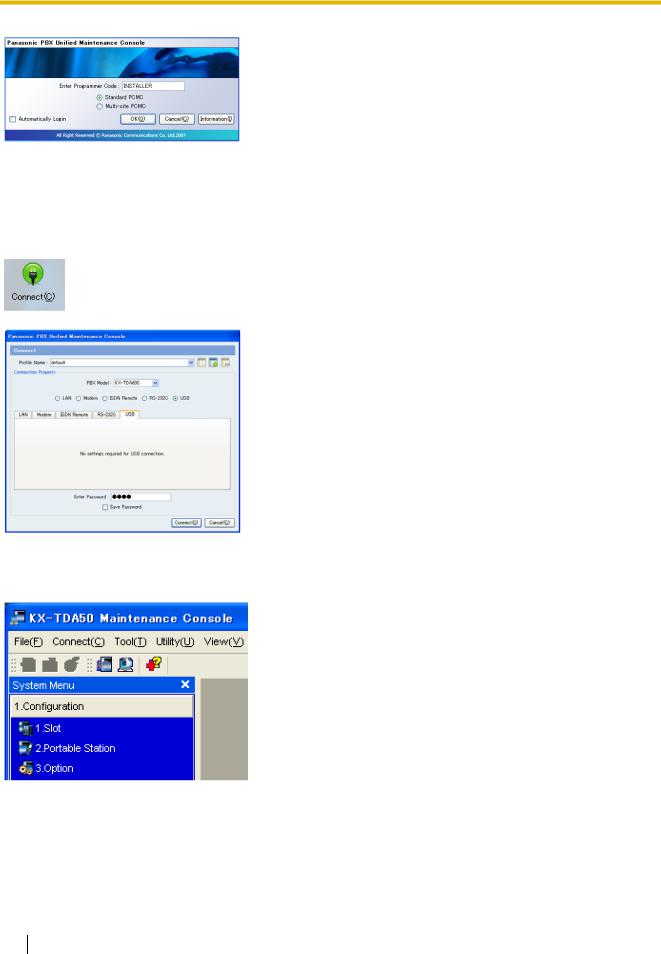
4.a. Enter the Installer Level Programmer Code (default:
INSTALLER).
The Programmer Code authorizes different programming levels, and the Quick Setup is only available when you start the Maintenance Console with the Installer Level Programmer Code.
Note
There are 2 other Programmer Codes with limited authorization: Administrator Level (default: ADMIN), and User Level (default: USER). (→ 1.2.2 Password Security)
b.Click OK.
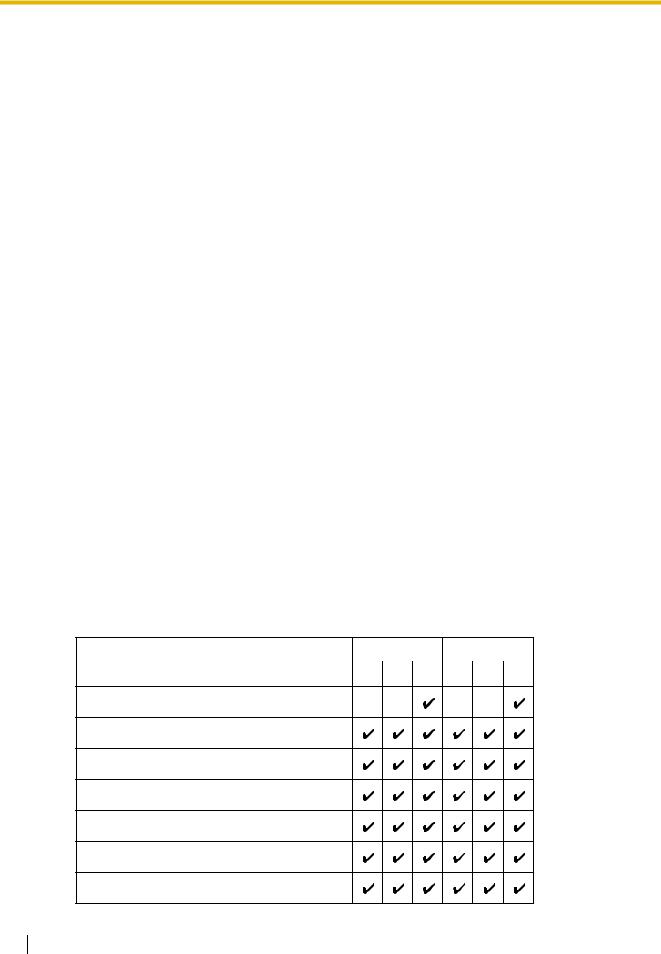
5.Click Connect.
6.a. Select the USB tab.
b.Enter the system password for installer (default:
1234).
c.Click Connect.
Note
To connect to the PBX via USB, the KX-TDA USB driver must be installed on the PC, as explained above in "Installing the Maintenance Console".
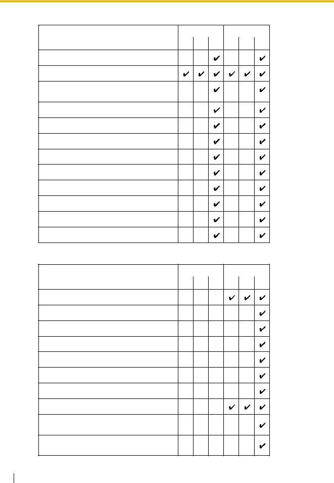
7.Follow the instructions of the Quick Setup wizard and assign the basic items.
The system menu appears. You may now begin programming the PBX.
Notice
1.During a long programming session, it is highly recommended that you periodically save the system data to the SD Memory Card. If the PBX undergoes a sudden power failure or if the system is reset for some reason, all the system data in RAM will be lost. However, if system data has been saved to the SD Memory Card, it can be easily restored.
14 PC Programming Manual

1.2 PC Programming
To save the system data to the SD Memory Card, (1) click the "SD Memory Backup" icon before resetting the PBX or turning off the power, or (2) exit the Maintenance Console so that the PBX automatically saves the system data.
2.The PC will not perform any shutdown operation, or enter the power-saving system standby mode while the Maintenance Console is connected to the PBX.
To perform either of the operations above, first close the connection to the PBX.
CAUTION
Do not remove the SD Memory Card while power is supplied to the PBX. Doing so may cause the PBX to fail to start when you try to restart the system.
1.2.2Password Security
To maintain system security, system passwords are required to access certain programming functions of the PBX. By giving different users access to different passwords, it is possible to control the amount of programming that each user is able to perform.
The following types of system passwords are available:
Password |
Description |
Format |
|
|
|
System Password for User |
Used with the user-level programmer code to access |
4 – 10 |
|
user-level PC programming. The installer can specify |
characters |
|
which system programming settings are available. |
|
|
|
|
System Password for |
Used with the administrator-level programmer code to |
|
Administrator |
access administrator-level PC programming. The |
|
|
installer can specify which system programming |
|
|
settings are available. |
|
|
|
|
System Password for |
Used with the installer-level programmer code to access |
|
Installer |
installer-level PC programming. All system |
|
|
programming settings are available. |
|
|
|
|
The three programmer codes used for PC programming can be set through Maintenance Console. For more information about programmer codes, see 2.1.2 Access Levels.
Warning to the Administrator or Installer regarding the system password
1.Please provide all system passwords to the customer.
2.To avoid unauthorized access and possible abuse of the PBX, keep the passwords secret, and inform the customer of the importance of the passwords, and the possible dangers if they become known to others.
3.The PBX has default passwords preset. For security, change these passwords the first time that you program the PBX.
4.Change the passwords periodically.
5.It is strongly recommended that passwords of 10 numbers or characters be used for maximum protection against unauthorized access. For a list of numbers and characters that can be used in system passwords, see 1.1.2 Entering Characters.
6.If a system password is forgotten, it can be found by loading a backup of the system data into a PC, and checking the password using the Maintenance Console software. If you do not have a backup of the system data, you must reset the PBX to its factory defaults and reprogram it. Therefore, we strongly recommend maintaining a backup of the system data.
PC Programming Manual |
15 |
|
|

1.2 PC Programming
For more information on how to back up the system data, refer to the on-line help of the Maintenance Console.
However, as system passwords can be extracted from backup copies of the system data file, do not allow unauthorized access to these files.
16 PC Programming Manual

Section 2
Maintenance Console Operating Instructions
This section serves as reference operating instructions when using the Maintenance Console software to program the PBX.
PC Programming Manual |
17 |
|
|

2.1 Introduction
2.1Introduction
2.1.1Starting Maintenance Console and Software Modes
Every time Maintenance Console is started, a dialog box will appear. From here, you can enter any of the 2 available software modes.
•Batch mode
Batch mode allows you to create new system data files, and make modifications to system data files stored on your PC, without being connected to the PBX. When you connect to the PBX, the modified data will be uploaded at one time.
•Interactive mode
Interactive mode allows you to directly modify the system data and settings stored in the PBX's memory from a PC that is connected to the PBX. This mode displays the system data that is currently being used by the PBX, rather than the system data stored on the SD memory card. Data can be modified and results displayed in real time.
To start Maintenance Console in Batch mode
1.Enter the relevant programmer code.
2.Click OK.
The start menu will appear.
3.Select an option.
•Select New to create a new system data file.
•Select Open to open an existing system data file.
To start Maintenance Console in Interactive mode
1.Enter the relevant programmer code.
2.Click OK.
The start menu will appear.
3.Click Connect.
Connection options will be displayed.
•Select a Profile Name if you want to use a pre-saved profile. This option is only available when one or more profiles have been previously stored.
a.Select the profile to use from the drop-down list.
b.If the system password for the PBX has not been stored with the profile, enter it.
If the system password has been stored with the selected profile, it does not need to be entered.
•To enter the parameters manually, select the PBX Model and select the method of connecting to the PBX.
a.Specify the settings as required. For more details, see the tables below.
b.Enter the system password for the PBX.
4.Click Connect.
Maintenance Console will start, and automatically connect to the PBX. If this is the first time that Maintenance Console has connected to the PBX, and the date and time of the PBX have not yet been set, the Quick Setup wizard will run. For more details, see Starting the Maintenance Console and Assigning the Basic Items (Quick Setup).
18 PC Programming Manual
|
|
|
|
2.1 Introduction |
|
|
|
|
|
Connection Settings for RS-232C |
|
|
||
|
|
|
|
|
|
|
Setting |
Values |
Explanation |
|
|
|
|
|
|
|
Port |
COMx |
Specify the number of the COM port assigned |
|
|
|
|
to the PC's RS-232C interface. Only available |
|
|
|
|
COM ports are displayed. |
|
|
|
|
|
|
|
Baud Rate (bps) |
2400, 4800, 9600, |
Specify the speed of data transmission. |
|
|
|
19200, 38400, 57600, |
|
|
|
|
115200 |
|
|
|
|
|
|
Connection Settings for Modem |
|
|
||
|
|
|
|
|
|
|
Setting |
Values |
Explanation |
|
|
|
|
|
|
|
Dial Number |
1-9, 0, *, #, -, "," |
Enter the telephone number to be dialed to |
|
|
|
[comma], T, P, W |
access the PBX. |
|
|
|
|
T: Converts the Dial Type from Pulse to Tone. |
|
|
|
|
"," [comma], P, W: Inserts a pause. |
|
|
|
|
|
|
|
Dial Type |
Auto(Tone), |
Specify the outgoing dialing method. |
|
|
|
Auto(Pulse), Manual |
If Manual is chosen, dialing must be done with |
|
|
|
|
a connected telephone. |
|
|
|
|
|
|
|
Comment |
Max. 40 characters |
Enter a comment to identify the set of values. |
|
|
|
|
|
|
|
Port |
COMx |
Specify the number of the COM port assigned |
|
|
|
|
to the PC's modem interface. |
|
|
|
|
Only available COM ports will be displayed. |
|
|
|
|
|
|
|
Baud Rate (bps) |
1200, 2400, 4800, 9600, |
Specify the speed of data transmission. |
|
|
|
19200, 38400 |
|
|
|
|
|
|
|
|
Modem Initialize |
– |
Enter the modem initialize command, and click |
|
|
|
|
Initialize to send the command to the modem. |
|
|
|
|
For more details, refer to your modem's |
|
|
|
|
instruction manual. |
|
|
|
|
|
Connection Settings for LAN |
|
|
||
|
|
|
|
|
|
|
Setting |
Values |
Explanation |
|
|
|
|
|
|
|
IP Address |
1.0.0.0– |
Specify the IP address of the PBX on the LAN. |
|
|
|
223.255.255.255 |
Enter the same IP address that was input in IP |
|
|
|
|
Address of 2.8.28 [1-1] Slot—Card Property |
|
|
|
|
- CTILINK (KX-TDA100/KX-TDA200/KX- |
|
|
|
|
TDA600 only). |
|
|
|
|
|
|
|
Port Number |
10000–65535 |
Specify the port number used to access the |
|
|
|
|
PBX via LAN. Enter the same port number that |
|
|
|
|
was input in Maintenance Port Number of |
|
|
|
|
2.8.28 [1-1] Slot—Card Property - CTILINK |
|
|
|
|
(KX-TDA100/KX-TDA200/KX-TDA600 only) |
|
|
|
|
or 2.8.19 [1-1] Slot—Card Property - IP |
|
|
|
|
Gateway (KX-TDA50 only). |
|
|
|
|
|
PC Programming Manual |
19 |
|
|
2.1 Introduction
2.1.2Access Levels
There are three main levels of access to the Maintenance Console: User, Administrator and Installer. Each level has its own Programmer Code, which must be entered to run the Maintenance Console. The allowed format for each programmer code is as follows:
Item |
Length |
|
|
User Level Programmer Code |
0 – 16 characters |
|
|
Administrator Level Programmer Code |
4 – 16 characters |
|
|
Installer Level Programmer Code |
4 – 16 characters |
|
|
Access to menu options within the Maintenance Console is restricted depending on the Programmer Code, and the current software mode (see 2.1.1 Starting Maintenance Console and Software Modes). When a menu option is limited to certain access levels, this is noted in this manual in the initial description of that menu option, for example:
"This option is only available at Installer level."
If a sentence like this does not appear under the heading, the menu option is available at all levels.
The target users for each access level are as follows:
Access Level |
User |
|
|
User |
For end users |
|
|
Administrator |
For system administrators |
|
|
Installer |
For dealers and system installers |
|
|
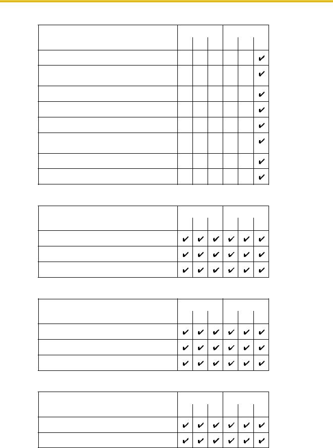
The options available in each mode and access level are shown below.
The access levels are abbreviated as follows:
U: User; A: Administrator; I: Installer
A check mark indicates that the menu option is available for that access level.
Start Menu
Menu Option |
Batch |
Interactive |
|
|
|
|
|
|
U |
A I |
U A I |
New
Open
Connect—RS-232C
Connect—USB
Connect—LAN
Connect—Modem
Connect—Profile Setup
20 PC Programming Manual
2.1 Introduction
File
Menu Option |
Batch |
Interactive |
|
|
|
|
|
|
U |
A I |
U A I |
Close
Save
Save As
Exit
Disconnect
Menu Option |
Batch |
Interactive |
|
|
U |
A |
I U A I |
Disconnect
Tool
Menu Option |
Batch |
Interactive |
|
|
|
|
|
|
U |
A |
I U A I |
SD memory backup
NDSS Link Data Clear
DXDP All OUS
Simplified Voice Message→Delete All
Recording
Simplified Voice Message→Check Current
Usage
Extension List View
Import→Feature - Speed Dial and Caller ID
Import→Incoming Call - DID Table (KX-
TDA100/KX-TDA200/KX-TDA600 only)
Import→ARS - Leading Digit
Import→ARS - Except Code
Import→ARS - Routing Plan
Import→Wired Extension
Import→PS Extension
Import→Quick Dial (Basic)
PC Programming Manual |
21 |
|
|
2.1 Introduction
Tool
Menu Option |
Batch |
Interactive |
|
|
|
|
|
|
U |
A I |
U A I |
Import→Quick Dial (MEC)
Export→Feature - Speed Dial and Caller ID
Export→Incoming Call - DID Table (KX-
TDA100/KX-TDA200/KX-TDA600 only)
Export→ARS - Leading Digit
Export→ARS - Except Code
Export→ARS - Routing Plan
Export→Wired Extension
Export→PS Extension
Export→Quick Dial (Basic)
Export→Quick Dial (MEC)
Screen Customize→User Level
Screen Customize→Administrator Level
Utility
Menu Option |
Batch |
Interactive |
|
|
|
|
|
|
U |
A I |
U A I |
Diagnosis
File Transfer PC to PBX (SD Card)
File Transfer PBX (SD Card) to PC
SD Card File View and Load
SD Card File Delete
Message File Transfer PC to PBX
Message File Transfer PBX to PC
Error Log
T1 Signaling Bit Monitor (KX-TDA100/KX-
TDA200/KX-TDA600 only)
T1 Line Trace (KX-TDA100/KX-TDA200/KX-
TDA600 only)
22 PC Programming Manual
2.1 Introduction
Utility
Menu Option |
Batch |
Interactive |
|
|
|
|
|
|
U |
A |
I U A I |
ISDN/QSIG Protocol Trace
Digital Trunk Error Report (KX-TDA100/KX-
TDA200/KX-TDA600 only)
IP Extension Statistical Information
CS Information
PS Information
Timed Update (KX-TDA100/KX-TDA200/KX-
TDA600 only)
System Reset→Reset by the Command
Flash ROM ID Information
View
Menu Option |
Batch |
Interactive |
|
|
|
|
|
|
U |
A |
I U A I |
Toolbar
Statusbar
System Menu
Window
Menu Option |
Batch |
Interactive |
|
|
|
|
|
|
U |
A |
I U A I |
Cascade
Tile(Horz)
Tile(Vert)
Help
Menu Option |
Batch |
Interactive |
|
|
|
|
|
|
U |
A |
I U A I |
Help
Additional Information
PC Programming Manual |
23 |
|
|

2.1 Introduction
Help
Menu Option |
Batch |
Interactive |
|
|
|
|
|
|
U |
A I |
U A I |
About
2.1.3Software Interface
This section explains the functions of the various elements of the software interface.
Main Window
The window of the Maintenance Console software is divided into several areas, as shown below:
24 PC Programming Manual

2.1 Introduction
1 |
2 |
3 |
|||
|
|
|
|
|
|
|
|
|
|
|
|
|
|
|
|
|
|
4 |
5 |
6 |
1. Menu Bar
Provides access to file management and connection options, as well as tools and utilities used in programming the PBX.
For details, see Sections 2.3 File to 2.7 Help.
2. Tool Bar
Provides easy access to commonly used software functions.
Two tool bars are provided, as follows:
•File
Contains the icon for saving files. For details, see Section 2.3.2 File—Save.
•Tools
Contains icons for backing up PBX data to the SD Memory Card, viewing extension
PC Programming Manual |
25 |
|
|

2.1 Introduction
information, and accessing Online Help. For details, see Sections 2.5.1 Tool—SD memory backup and 2.5.6 Tool—Extension List View.
These menus can be positioned freely. Click and drag the title bar of a menu to move it to another position. It will automatically snap in to position above, below, to the left, or to the right of the main window if released there. Otherwise, it will float separately from the main window.
Whether the tool bar is displayed or not can be chosen by selecting Toolbar from the View menu.
3. Tab Bar
The name of each screen currently open is displayed in a tab in this tab bar. When multiple screens are open at the same time, click on the tab of a screen to display the options associated with that screen.
4. System Menu
Provides access to the settings used for programming the PBX, grouped into 11 topics. For details, see Sections 2.8 [1] Configuration to 2.18 [11] Maintenance.
To display the individual screens within a topic, click the topic heading. It will expand to show the subtopics.
•If a sub-topic contains more than one screen, clicking the name of the sub-topic will display the names of individual screens. Clicking an expanded sub-topic will hide the names of individual screens.
Double-click on a screen name to open that screen in 6. Main Screen below.
This menu can be positioned freely. Click and drag the title bar of the menu to move it to another position. It will automatically snap in to either the left side or right side of the main window if released there. Otherwise, it will float separately from the main window.
Whether the system menu is displayed or not can be chosen by selecting System Menu from the View menu.
5. Status Bar
The status bar displays information on the current state of the Maintenance Console.
Whether the status bar is displayed or not can be chosen by selecting Statusbar from the View menu.
The information displayed is as follows, in order from left to right:
Area |
Values |
Description |
|
|
|
Program Mode |
Batch Mode xxx |
See 2.1.1 Starting Maintenance |
|
Interactive Mode |
Console and Software Modes above. |
|
"xxx" is replaced by the name of the |
|
|
|
|
|
|
current system data file. |
|
|
|
PBX Type |
Type: TDA50/TDA100/ |
Displays the type of PBX being |
|
TDA200/TDA600 |
programmed. |
|
|
|
Access Level |
Level : |
Displays the current access level, |
|
User |
determined by the Programmer Code |
|
Administrator |
entered when starting Maintenance |
|
Installer |
Console. See 2.1.2 Access Levels for |
|
|
more information. |
|
|
|
26 PC Programming Manual
|
|
|
2.1 Introduction |
|
|
|
|
|
|
|
|
|
|
|
|
Area |
Values |
Description |
|
|
|
|
|
|
|
PBX System Data |
Versionxxx-xxx |
Displays the version number of the |
|
|
Version |
|
system software installed to the PBX. |
|
|
|
|
The first 3 digits are the version number, |
|
|
|
|
and the last 3 digits are the revision |
|
|
|
|
number. |
|
|
|
|
|
|
|
PBX Region Code |
Regionxxx-xxx |
Displays the region code assigned to the |
|
|
|
|
PBX and Maintenance Console. |
|
|
|
|
The first 3 digits represent the region |
|
|
|
|
code assigned to the PBX, and the last 3 |
|
|
|
|
digits represent the region code |
|
|
|
|
assigned to the Maintenance Console. |
|
|
|
|
|
|
6. Main Screen
Displays the screens selected from 4. System Menu above.
For details, see Sections 2.8 [1] Configuration to 2.18 [11] Maintenance.
Standard Buttons and Elements
There are several standard buttons that are displayed on many screens within the Maintenance Console.
The standard buttons are as follows:
Button |
Function |
|
|
OK |
Implements changes and closes the current screen. |
|
|
Cancel |
Abandons changes and returns to the previous screen. |
|
|
Close |
Keeps any changes implemented, and closes the current screen. |
|
|
Apply |
Implements changes and remains on the same screen. |
|
|
Refresh |
Implements changes, updates displayed data, and remains on the |
|
current screen. |
|
|
Help |
Displays the relevant help topic for the current screen. |
|
|
In addition, many screens within the software display a small open folder icon ( ) beside lists of setting items. Clicking this icon will collapse part of the list, allowing other items to be displayed. The
icon will change to a closed folder ( ).
).
Clicking the closed folder icon will expand the list again.
2.1.4Card Status
Certain tools, utilities and settings require that the target card be set to out-of-service (OUS) or inservice (INS) status before the operation is carried out. Where required, this is noted in the description of each item. Card status changes can only be performed when the software is in Interactive mode (see 2.1.1 Starting Maintenance Console and Software Modes).
•"In service" means that the card is installed correctly in the PBX, and is capable of being used normally.
PC Programming Manual |
27 |
|
|

2.1 Introduction
•"Out of service" means that the card is installed correctly in the PBX, but has been temporarily removed from use. This allows settings to be modified or software to be upgraded.
•"Fault" means that the card is not installed in the PBX correctly, or is not functioning correctly. For more information, see the Installation Manual.
For details about how to change the status of a card, see To change the status (INS/OUS) of a card (Interactive mode only) on screen 2.8.1 [1-1] Slot.
2.1.5Display Options
The View and Window menus provide options to control the display of items within the Maintenance Console.
•View
–Toolbar: Displays or hides the tool bar of commonly used buttons.
–Statusbar: Displays or hides the bar at the bottom of the Maintenance Console window.
–System Menu: Displays or hides the menu of PBX setting screens.
•Window
–Cascade: When multiple data screens are open, displays all open screens overlapped, with the title bars visible.
–Tile(Horz): When multiple data screens are open, displays all open screens side by side.
–Tile(Vert): When multiple data screens are open, displays all open screens vertically.
2.1.6Extension Number Setting
Many screens within the Maintenance Console software allow you to select extensions as part of programming various features (for example, as members of a group). These screens use a standard window to make selecting multiple extensions easy, accessed by clicking a button. This section explains how to use this Extension Number Setting window.
To select multiple extension numbers, select the type of extension to display, highlight the extensions you wish to add, then click the Add button. When finished, click OK. Data for the selected extensions will be added to the first free spaces on the original screen.
 Extension Type
Selects the types of extension numbers to display in Extension Numbers & Names List. Multiple items can be selected. Items that are not available are shown with a grey checkbox.
Default
None selected.
Value Range
Wired Extension, Portable Station, VM Group(DPT), VM Group(DTMF), ICD Group, PS Ring Group, OGM(DISA), External Pager, Analog MODEM
28 PC Programming Manual

2.1 Introduction
 Extension Numbers & Names List
Displays all available extensions of the types selected in Extension Type, and names. Click entries to select them, and click the Add button when finished, to add the selected extensions. To deselect an entry, click it again.
Default
Available extensions.
Value Range
Matching extensions
 Available Column
Specifies which fields in the original form to add extension data to. For example, if both extension numbers and names can be entered in the original form, it is possible to specify that extension name data not be transferred, by deselecting that field here.
To select or deselect a field, click its name.
Default
First available field
Value Range
Available fields
 Selected Extension List
Displays the extensions that have been selected to be added to member data. To remove an extension from this list, click it to select it and click Delete.
Default
Not stored.
Value Range
Selected extensions
PC Programming Manual |
29 |
|
|

2.2 Start Menu
2.2Start Menu
2.2.1Start Menu—New
Creates a new system data file, used to program the PBX in Batch mode. All settings are in their initial or default state.
This option is only available at Installer level.
To upload the file created here to the SD memory card installed in the PBX, see 2.6.2 Utility—File Transfer PC to PBX (SD Card).
Note
Since selecting this option creates a blank system data file, uploading this file to the PBX will overwrite all previous settings. Use only when necessary.
To create a new system data file
1.From the start menu, select New.
2.Click the appropriate model number.
3.Select whether an EMEC (KX-TDA600) or MEC (KX-TDA50/KX-TDA100/KX-TDA200) card is installed or not.
4.Click OK.
2.2.2Start Menu—Open
Opens a system data file previously saved on the PC, and enters Batch mode.
When opening a file created with an older version of the Maintenance Console, you will be asked whether you want to convert the data for use with the current version or not. Using the data without converting may result in some data being loaded to an incorrect destination, and is not recommended.
If the file is not supported by the PBX (e.g. a system data file from an incompatible PBX), it will not be opened. The only files that can be opened are files that were created by the Maintenance Console for a supported PBX.
To upload a file opened here to the SD memory card installed in the PBX, see 2.6.2 Utility—File Transfer PC to PBX (SD Card).
To open a system data file
1.From the start menu, select Open. The Open dialog box will be displayed.
2.Navigate to the folder containing the system data file you want to open.
3.Select the file.
4.Click Open.
If the file was created with an older version of the Maintenance Console, you will be asked if you want to convert the data.
• Click Yes to convert the data for use with the current version of the Maintenance Console.
30 PC Programming Manual
Loading...