


FV-08-11VFM5

INSTALLATION INSTRUCTIONS
Ventilating Fan
FV-08-11VFM5
Model No.
FV-08-11VFM5
FV-08-11VF5
Contents
GENERAL SAFETY INFORMATION
DESCRIPTION
UNPACKING
SUPPLIED ACCESSORIES
DIMENSIONS
WIRING DIAGRAM
FEATURE
INSTALLATION (NEW CONSTRUCTION)
INSTALLATION (RETROFIT)
MAINTENANCE (CLEANING)
2-3
4
4
4
5
6
6
7-8
9
10
PRACTICAL GUIDE TO INSTALLATION
SPECIFICATIONS
FV-08-11VF5
PRODUCT SERVICE BACK COVER
READ AND SAVE THESE INSTRUCTIONS
Thank you for purchasing this Panasonic product.
Please read these instructions carefully before attempting to install, operate or service
the Panasonic product. Failure to comply with instructions could result in personal injury
or property damage. Please explain to users how to operate and maintain the product
after installation, and this booklet should be presented to users.
Please retain this booklet for future reference.
11
11
GENERAL SAFETY INFORMATION
For Your Safety
To reduce the risk of injury, loss of life, electric shock, fire, malfunction, and damage to equipment
or property, always observe the following safety precautions.
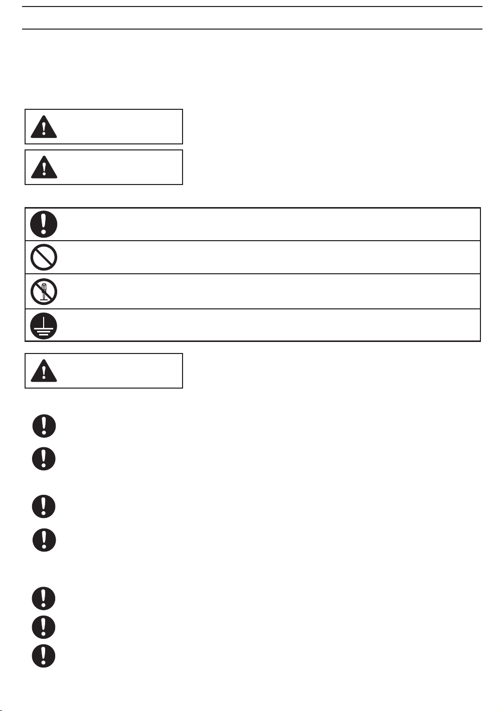
Explanation of symbol word panels
The following symbol word panels are used to classify and describe the level of hazard, injury, and
property damage caused when the denotation is disregarded and improper use is performed.
WARNING
CAUTION
The following symbols are used to classify and describe the type of instructions to be observed.
This symbol is used to alert users to a specific operating procedure that must be followed
in order to operate the unit safely.
This symbol is used to alert users to a specific operating procedure that must not be
performed.
This symbol is used to alert users not to disassemble the equipment.
This symbol is used to alert users to make sure of grounding when using the equipment
with the grounding terminal.
Denotes a potential hazard that could result in serious injury
or death.
Denotes a hazard that could result in minor injury.
WARNING
To reduce the risk of fire, electric shock or injury to persons, observe the following :
Use this unit only in the manner intended by the manufacturer. If you have any questions,
contact the manufacturer.
Before servicing or cleaning unit, switch power off at service panel and lock the service
disconnecting means to prevent power from being switched on accidentally. When the
service disconnecting means cannot be locked, securely fasten a prominent warning device,
such as a tag, to the service panel.
Installation work and electrical wiring must be done by qualified person(s) in accordance with
all applicable codes and standards, including fire-rated construction.
Sufficient air is needed for proper combustion and exhausting of gases through the flue (chimney)
of fuel burning equipment to prevent back drafting. Follow the heating equipment manufacturer's
guideline and safety standards such as those published by the National Fire Protection Association
(NFPA), and the American Society for Heating, Refrigeration and Air Conditioning Engineers
(ASHRAE) and the local code authorities.
When cutting or drilling into wall or ceiling, do not damage electrical wiring and other
hidden utilities.
Ducted fans must always be vented to the outdoors.
If this unit is to be installed over a tub or shower, it must be marked as appropriate for the
application and be connected to a GFCI(Ground Fault Circuit Interrupter) - protected branch
circuit.
2
GENERAL SAFETY INFORMATION CONTINUED
WARNING
These models are UL listed for tub and shower enclosures.
Canada only: Not to be installed in a ceiling thermally insulated to a value greater than R40.
Do not disassemble the unit for reconstruction. It may cause fire or electric shock.
A statement to the effect that when the product is to no longer be used, it must not be left
in place but remove, to prevent it from possibly falling.
Ceiling joist must be subjected to static load more than five times the weight of the product.
Do not install with a method which is not approved in the instructions.
Do not use these fans with any solid-state speed control device. Solid state controls may cause
harmonic distortion which can cause motor humming noise.
These products must be properly grounded.
CAUTION
Do not install these ventilating fans where interior room temperature
may exceed 104°F(40°C).
Make sure that the electric service supply voltage is AC 120V, 60Hz.
Follow all local electrical and safety codes, as well as the National
Electrical Code (NEC) and the Occupation Safety and Health Act (OSHA).
Always disconnect the power source before working on or near the fan,
motor or junction box.
Protect the supply wiring from sharp edges, oil, grease, hot surfaces,
chemicals or other objects.
Do not kink the supply wiring.
Provide make up air for proper ventilation.
For general ventilating use only. Do not use to exhaust hazardous or
explosive materials and vapors.
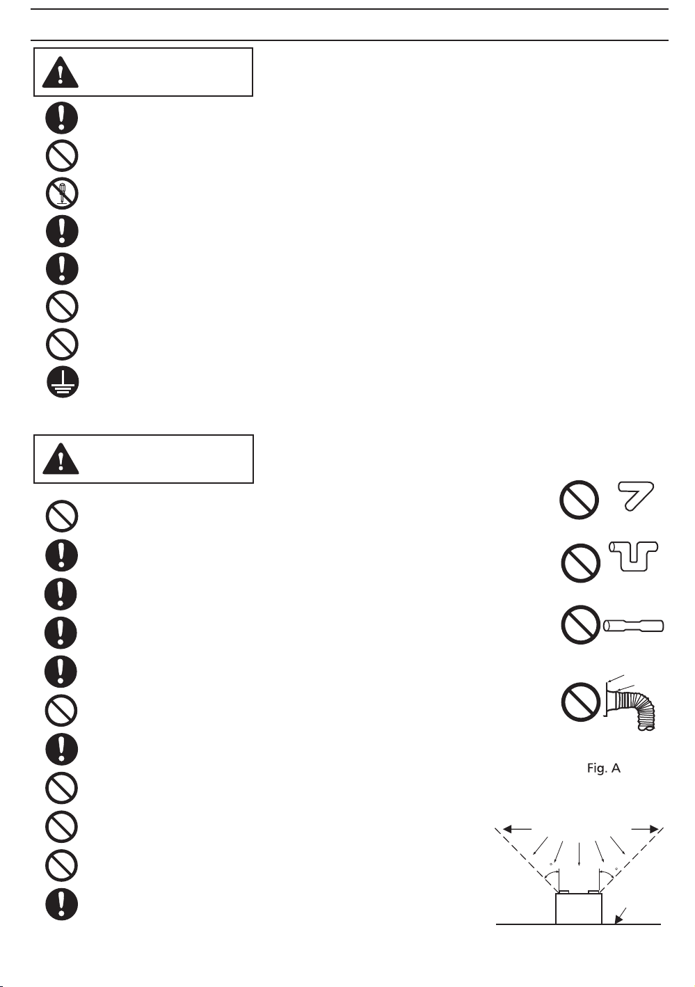
Do not install the unit where ducts are configured as shown
in Fig.A.
Not for use in cooking area. (Fig.B)
Prohibited
Prohibited
Prohibited
Prohibited
(Cooking area)
Do not install above or
inside this area
45
Bend
repeatedly
Bend near
45
Extreme
bending
Duct
narrow
Fan body
Adaptor
adaptor
The special-purpose or dedicated parts, such as mounting
fixtures, must be used if such parts are provided.
Cooking
equipment
Fig. B
Floor
3
These Panasonic ventilating fan models are listed by UL under UL file No. E78414.
These Panasonic ventilating fan models use a sirocco Blower driven b y a capacitor motor.
The motor is designed to have an extended service life with reduced energy consumption. It also
incorporates a thermal-cutoff for safety. The grille covering the fan body is a spring-loaded, quick
remove type. A damper for preventing air counterflow is provided. The blower uses a high-capacity
sirocco fan developed to reduce the noise level.
These products have two speeds. “ 80” is low airflow and "110" is high a irflow.
FV-08-11VFM5 is equipped w ith a motion sensor that shifts the fan to vent automatically when
motion is detected. It stops the flow automatically after 20 minutes when motion is no longer
detected.
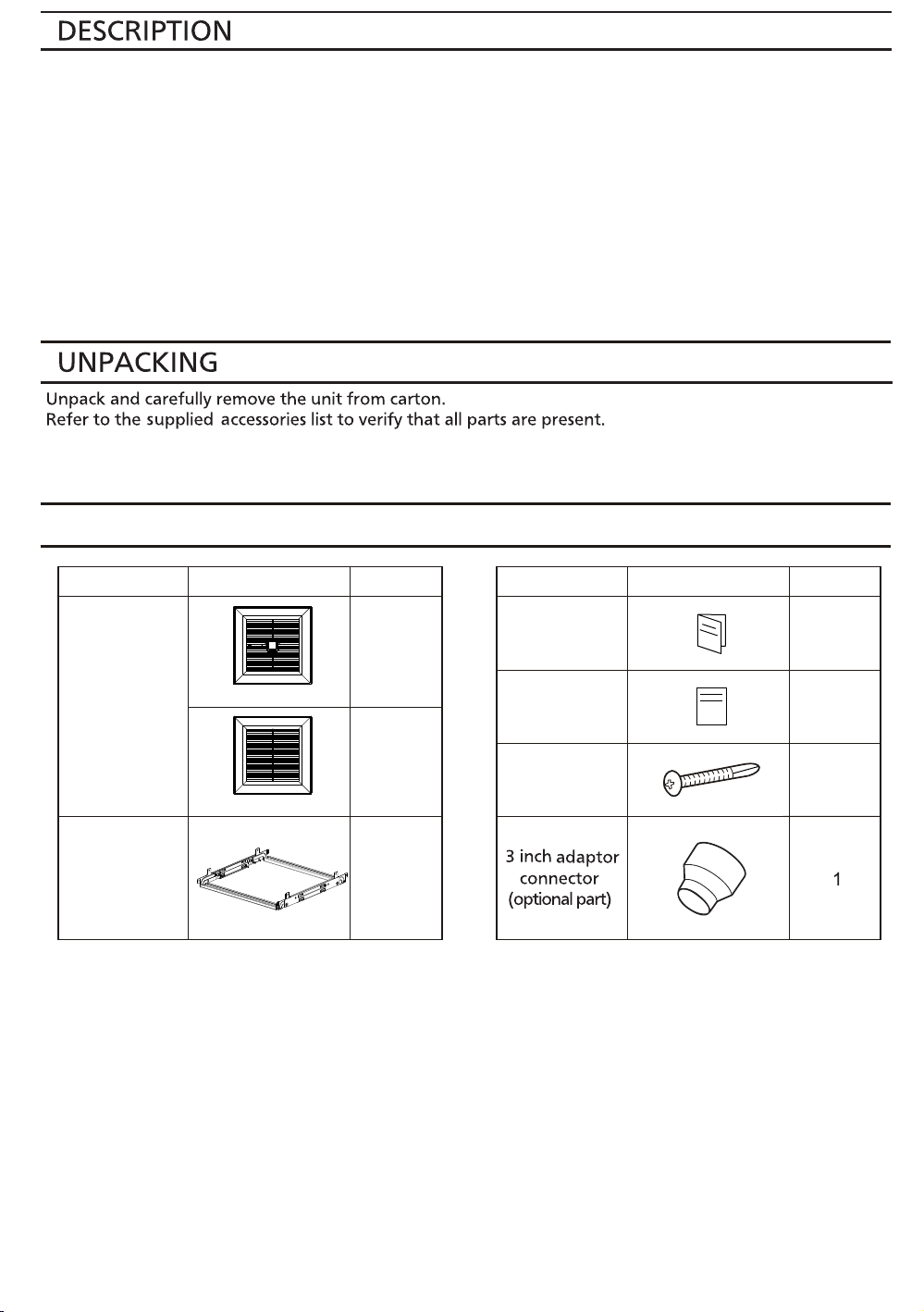
SUPPLIED ACCESSORIES
Part name
Grille
Flex-Z Fast
bracket
(with 4 tapping
screw-
ST4.2X20)
TM
Appearance Quantity
1
FV-08-11VFM5
1
FV-08-11VF5
1
Part name
Installation
instructions
Warranty
sheet
Self-drilling
screw
Appearance Quantity
2
1
4
4
 Loading...