


2
TABLE OF CONTENTS |
|
Introduction............................................................................. |
4 |
Specifications........................................................................... |
6 |
Installation............................................................................... |
7 |
Operational Start-Up.............................................................. |
9 |
Troubleshooting .................................................................... |
11 |
Flow Monitor Information................................................... |
12 |
Repair Kit Information ........................................................ |
13 |
Statement of Warranty......................................................... |
15 |
3
INTRODUCTION
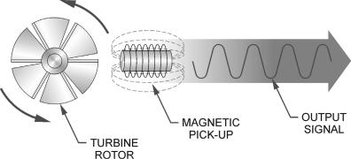
Fluid entering the meter passes through the inlet flow straightener which reduces its turbulent flow pattern and improves the fluid’s velocity profile. Fluid then passes through the turbine blades causing it to rotate at a speed proportional to the fluid velocity. As each blade passes through the magnetic field, created at the base of the pickoff transducer, AC voltage (pulse) is generated in the pick-up coil (see Figure 1). These impulses produce an output frequency proportional to the volumetric flow through the meter. The output frequency is used to represent flow rate and/or totalization of fluid passing through the turbine flow meter.
FIGURE 1
Schematic illustration of electric signal generated by rotor movement
TURBINE METER
The FTB-1400 Series Turbine Flow Meter is designed to withstand the rigorous demands of the most remote flow measurement applications. The FTB-1400 Series Flow Meter maintains measurement accuracy and mechanical integrity in the corrosive and abrasive fluids commonly found in oil field waterflood project pipelines, in-situ mining operations, offshore facilities and plant locations. Simple to install and service, it can operate in any orientation (horizontal to vertical) as long as the
4
“flow direction” arrow is aligned in the same direction as the actual line flow. For optimum performance, the flow meter should be installed with a minimum of 10 diameters upstream pipe length and 5 diameters downstream pipe length.
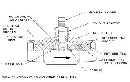
FIGURE 2
Typical cross-section of FTB-1411 through
FTB-1441 turbine flow meter
5
 Loading...