


 Loading...


 User’sGuide
omega.com®
 OMEGA®
http://www.omega.com e-mail: info@omega.com
CN491A SERIES
1/32 DIN Temperature/Process Controllers

omega.com®
 OMEGA®
|
OMEGAnet® On-Line Service |
Internet e-mail |
|
|
http://www.omega.com |
info@omega.com |
|
|
Servicing North America: |
||
USA: ISO 9001 Certified |
Canada: |
||
One Omega Drive, Box 4047 |
976 Bergar |
||
Stamford, CT 06907-0047 |
Laval (Quebec) H7L 5A1 |
||
Tel: (203) 359-1660 |
Tel: (514) 856-6928 |
||
FAX: (203) 359-7700 |
FAX: (514) 856-6886 |
||
e-mail: info@omega.com |
e-mail: info@omega.ca |
||
For immediate technical or application assistance: |
|||
USA and Canada: |
Mexico and Latin America: |
||
Sales Service: 1-800-826-6342 / 1-800-TC-OMEGASM |
Tel: (95) 800-826-6342 |
||
Customer Service: 1-800-622-2378 / 1-800-622-BESTSM |
FAX: (95) 203-359-7807 |
||
Engineering Service: 1-800-872-9436 / 1-800-USA- |
~ |
|
|
En Espanol: (95) 203-359-7803 |
|||
WHENSM TELEX: 996404 EASYLINK: 62968934 |
e-mail: espanol@omega.com |
||
CABLE: OMEGA |
|
|
|
Servicing Europe:
Benelux:
Postbus 8034, 1180 LA Amstelveen The Netherlands
Tel: (31) 20 6418405 FAX: (31) 20 6434643 Toll Free in Benelux: 0800 0993344 e-mail: nl@omega.com
Czech Republic:
ul. Rude armady 1868, 733 01 Karvina-Hranice Tel: 420 (69) 6311899 FAX: 420 (69) 6311114 Toll Free: 0800-1-66342
e-mail: czech@omega.com
France:
9, rue Denis Papin, 78190 Trappes
Tel: (33) 130-621-400 FAX: (33) 130-699-120 Toll Free in France: 0800-4-06342
e-mail: france@omega.com
Germany/Austria:
Daimlerstrasse 26, D-75392
Deckenpfronn, Germany
Tel: 49 (07056) 3017 FAX: 49 (07056) 8540 Toll Free in Germany: 0130 11 21 66 e-mail: info@omega.de
United Kingdom: ISO 9002 Certified
One Omega Drive
River Bend Technology Centre Northbank, Irlam Manchester, M44 5EX, England Tel: 44 (161) 777-6611
FAX: 44 (161) 777-6622
Toll Free in the United Kingdom: 0800-488-488 e-mail: info@omega.co.uk
It is the policy of OMEGA to comply with all worldwide safety and EMC/EMI regulations that apply. OMEGA is constantly pursuing certification of its products to the European New Approach Directives. OMEGA will add the CE mark to every appropriate device upon certification.
The information contained in this document is believed to be correct, but OMEGA Engineering, Inc. accepts no liability for any errors it contains, and reserves the right to alter specifications without notice. WARNING: These products are not designed for use in, and should not be used for, patient-con- nected applications.

TABLE OF CONTENTS
Introduction . . . . . . . . . . . . . . . . . . . . . . . . . . . . . . . . . . . . . . . . . . .2 Fuzzy Logic . . . . . . . . . . . . . . . . . . . . . . . . . . . . . . . . . . . . . . . . . . . .2 Specifications . . . . . . . . . . . . . . . . . . . . . . . . . . . . . . . . . . . . . . . . . .4 Input Range . . . . . . . . . . . . . . . . . . . . . . . . . . . . . . . . . . . . . . . . . . .5 Model Configuration . . . . . . . . . . . . . . . . . . . . . . . . . . . . . . . . . . . .6 Installation . . . . . . . . . . . . . . . . . . . . . . . . . . . . . . . . . . . . . . . . . . . .7 Wiring & Mounting . . . . . . . . . . . . . . . . . . . . . . . . . . . . . . . . . . . . .7 Negotiating the menu . . . . . . . . . . . . . . . . . . . . . . . . . . . . . . . . . .11 Learning the parameters . . . . . . . . . . . . . . . . . . . . . . . . . . . . . . . .12 Primary Program Menu . . . . . . . . . . . . . . . . . . . . . . . . . . . . . . . . .16 Changing Setpoint . . . . . . . . . . . . . . . . . . . . . . . . . . . . . . . . . . . . .17 Begin Controlling . . . . . . . . . . . . . . . . . . . . . . . . . . . . . . . . . . . . . .17 Flow Chart of Parameters . . . . . . . . . . . . . . . . . . . . . . . . . . . . . . .18 Auto-tuning . . . . . . . . . . . . . . . . . . . . . . . . . . . . . . . . . . . . . . . . . . .20 Alarms . . . . . . . . . . . . . . . . . . . . . . . . . . . . . . . . . . . . . . . . . . . . . . .21 Setting Alarms . . . . . . . . . . . . . . . . . . . . . . . . . . . . . . . . . . . . . . . .23 Scaling Analog Inputs/Setting Setpoint Limits . . . . . . . . . . . . . .24 Ramp Function . . . . . . . . . . . . . . . . . . . . . . . . . . . . . . . . . . . . . . . .26 Ramp & Soak/Dwell Function . . . . . . . . . . . . . . . . . . . . . . . . . . . .27 Tool Program Menu . . . . . . . . . . . . . . . . . . . . . . . . . . . . . . . . . . . .29 Flow Chart of Tool Programs . . . . . . . . . . . . . . . . . . . . . . . . . . . . .30 Manual Control . . . . . . . . . . . . . . . . . . . . . . . . . . . . . . . . . . . . . . . .32 Programmable Control Action . . . . . . . . . . . . . . . . . . . . . . . . . . .33 Cooling Control . . . . . . . . . . . . . . . . . . . . . . . . . . . . . . . . . . . . . . . .34 Configurable Menus . . . . . . . . . . . . . . . . . . . . . . . . . . . . . . . . . . . .35 Locking Menus . . . . . . . . . . . . . . . . . . . . . . . . . . . . . . . . . . . . . . . .37 Error Messages . . . . . . . . . . . . . . . . . . . . . . . . . . . . . . . . . . . . . . .38
1

INTRODUCTION
General Description
The CN491A is a fully programmable, microprocessor-based temperature/process controller. It offers superior control with 200 msec sampling rate and by using fuzzy logic to enhance its P, I and D parameters. The 4-digit 0.4” red LED display offers excellent visibility on a unit that is 1/32 DIN in size.
The CN491A is available with either 20-32V AC/DC or 90-264V AC power supply. This is a single universal input unit that will accept 8 different thermocouple types, Pt100 RTDs, and a variety of linear mA and VDC signals. The wide range of options for the two available outputs include relays, SSR drives, 4-20mA, 0-20mA, or 0-10VDC. Output #1 can be used in either a direct or reverse action control situation with a programmable ramp rate. Output #2 can be used as a control output, as an alarm, or as a dwell timer.
Optional features include 2-wire RS-485 serial communications with Windows 95™-based software, and Analog Retransmission of process variable, setpoint variable or the percentage of control output, as a 0-20 mA/4-20 mA DC signal.
The communications software package, CN491A-SOFT, offers excellent graphics, bar and trend displays, and supports easy-to- use database control and back-up capability.
FUZZY LOGIC
The function of Fuzzy Logic is to adjust the PID parameters internally in order to make the control output more flexible and adaptive to the process. One of the best analogies would compare Fuzzy Logic to the abilities of a good driver. The driver is
2
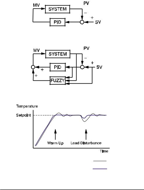
able to control a car well at a variety of speeds and under varying circumstances by using knowledge gained through previous experience.
Fuzzy Logic combined with PID control has been proven to be an efficient method to improve control stability. This is illustrated in figure 3.
Figure 1. PID only
Figure 2. PID with fuzzy logic
PID control with proper tuning
PID + Fuzzy control
Figure 3. PID vs. PID and fuzzy logic
3

0-360°F, 0-200°C, 0-3600 Process Units 0-3600 seconds
0-1000 seconds
0-55.55°C/min, 0-99.99°F/min,
0-99.99 Process Units(P.U.)/min
0-9999 minutes
0.1-11.0°C, 0.1-19.9°F, 0.1-199 P.U. 0-99 seconds
Direct (cooling) and reverse(heating)
3A/240 VAC (resistive) 24 VDC/20 mA max.
Linear, max. load 500 ohms Linear, max. load 500 ohms
Linear, min. input impedance 500K ohms
0.4” red LED, 4 digits Control output and alarm
4

POWER |
|
Rating: |
90-264VAC nominal, 264V excursion (max) |
|
50/60Hz or 20-32V AC/DC |
Consumption: |
Less than 5VA |
ENVIRONMENTAL & PHYSICAL |
|
Safety: |
CE & CSA Approved, & UL Recognized |
Protection: |
NEMA 4X (indoor use), IP65 |
Operating Temperature: |
-10 to 50°C (14 to 122°F) |
Humidity: |
0 to 90%RH (non-condensing) |
Insulation: |
20 Mohm min. (500 VDC) |
Breakdown: |
AC2000V. 50/60Hz. 1 minute |
Vibration: |
10-55Hz. amplitude 1mm |
Shock: |
200 m/s2 (20g) |
Weight: |
110 grams |
Dimension: |
24(H) x 48(W) x 99mm (depth behind panel) |
Panel cutout: |
22.2mm(H) (+.3/-0) 45 mm(W) (+.5/-0) |
RANGE AND ACCURACY OF INPUTS
SENSOR |
INPUT TYPE |
RANGE (°F) |
RANGE (°C) |
ACCURACY |
J |
Iron-Constantan |
-58 to 1830 |
-50 to 999 |
±3.6°F/±2°C |
K CHROMEGA − ALOMEGA |
-58 to 2500 |
-50 to 1370 |
±3.6°F/±2°C |
|
T |
Copper-Constantan |
-454 to 752 |
-270 to 400 |
±3.6°F/±2°C |
E |
CHROMEGA -Constantan |
-58 to 1382 |
-50 to 750 |
±3.6°F/±2°C |
B |
Pt30%Rh/Pt6%Rh |
572 to 3272 |
300 to 1800 |
±3.6°F/±2°C |
R |
Pt13%Rh/Pt |
32 to 3182 |
0 to 1750 |
±3.6°F/±2°C |
S |
Pt10%Rh/Pt |
32 to 3182 |
0 to 1750 |
±3.6°F/±2°C |
N |
Nicrosil-Nisil |
-58 to 2372 |
-50 to 1300 |
±3.6°F/±2°C |
RTD |
Pt100 ohm (DIN) |
-328 to 842 |
-200 to 450 |
±0.72°F/±0.4°C |
RTD |
Pt100ohm (JIS) |
-328 to 842 |
-200 to 450 |
±0.72°F/±0.4°C |
|
|
|
|
|
LINEAR INPUTS (All scalable) |
|
|
|
|
Input type |
|
Range |
Accuracy |
|
4-20 mA, 0-20 mA, 0-1V, 0-5V, 1-5V, 0-10V |
-1400 to 9400 |
±0.05% FS |
||
5

CN491A MODEL CONFIGURATION
Model No |
Description |
|
CN491A-R1 |
Relay Output |
|
CN491A-D1 |
DC Pulse Output |
|
CN491A-F1A |
4-20mA Output |
|
CN491A-F1B |
0-20mA Output |
|
CN491A-V1 |
0-10V Output |
|
|
|
|
|
|
|
SECOND OUTPUT/ALARM |
|
|
Suffix |
Description |
|
-R2 |
Relay |
|
-D2 |
DC pulse |
|
-F2A |
4-20mA |
|
-F2B |
0-20mA |
|
-V2 |
0-10V |
|
|
|
|
|
|
|
AUXILIARY OPTIONS |
|
|
Suffix |
Description |
|
-C4 |
RS-485 Communications |
|
-PVSV |
0-20mA/4-20mA retransmission |
|
|
|
|
|
|
|
OPTIONAL POWER SUPPLY |
||
|
|
|
Suffix |
Description |
|
-LV |
20-32V AC/DC |
|
|
|
|
6
INSTALLATION
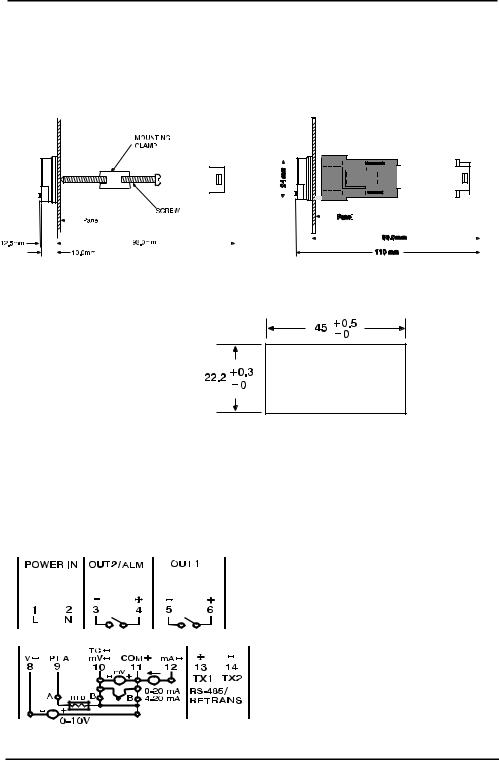
MOUNTING
Install mounting clamp(s). Gently tighten clamp until the controller fits snugly against the front panel.
|
|
|
|
|
|
|
|
|
|
|
|
|
|
|
|
|
|
|
|
|
|
|
|
|
|
|
|
|
|
|
|
|
|
|
|
|
|
|
|
|
|
|
|
|
|
|
|
|
|
|
|
|
|
|
|
|
|
|
|
|
|
|
|
|
|
|
|
|
|
|
|
|
|
|
|
|
|
|
|
|
|
|
|
|
|
|
|
|
|
|
|
|
|
|
|
|
|
|
|
|
|
|
|
|
|
|
|
|
|
|
|
|
|
|
|
|
|
|
|
|
|
|
|
|
|
|
|
|
|
|
|
|
|
|
|
|
|
|
|
|
|
|
|
|
|
|
|
|
|
|
|
|
|
|
|
|
|
|
|
|
|
|
|
|
|
|
|
|
|
|
|
|
|
|
|
|
|
|
|
|
|
|
|
|
|
|
|
|
|
|
|
|
|
|
|
|
|
|
|
|
|
|
|
|
|
|
|
|
|
|
|
|
|
|
|
|
|
|
|
|
|
|
|
|
|
|
|
|
|
|
|
|
|
|
|
|
|
|
|
|
|
|
|
|
|
|
|
|
|
|
|
|
|
|
|
|
|
|
|
|
|
|
|
|
|
|
|
|
|
|
|
|
|
|
|
|
|
|
|
|
|
|
|
|
|
|
|
|
|
|
|
|
|
|
|
|
|
|
|
|
|
|
|
|
|
|
|
|
|
|
|
|
|
|
|
|
|
|
|
|
|
|
|
|
|
|
|
|
|
|
|
|
|
|
|
|
|
|
|
|
|
|
|
|
|
|
|
|
|
|
|
|
|
|
|
|
|
|
|
|
|
|
|
|
|
|
|
|
|
|
|
|
|
|
|
|
|
|
|
|
|
|
|
|
|
|
|
|
|
|
|
|
|
|
|
|
|
|
|
|
|
|
|
|
|
|
|
|
|
|
|
|
|
|
|
|
|
|
|
|
|
|
|
|
|
|
|
|
|
|
|
|
|
|
|
|
|
|
|
|
|
|
|
|
|
|
|
|
|
|
|
|
|
|
|
|
|
|
|
|
|
|
|
|
|
|
|
|
|
|
|
|
|
|
|
|
|
|
|
|
|
|
|
|
|
|
|
|
|
|
|
|
|
|
|
|
|
|
|
|
|
|
|
|
|
|
|
|
|
|
|
|
|
|
|
|
|
|
|
|
|
|
|
|
|
|
|
|
|
|
|
|
|
|
|
|
|
|
|
|
|
|
|
|
|
|
|
|
|
|
|
|
|
|
|
|
|
|
|
|
|
|
|
|
|
|
|
|
|
|
|
|
|
|
|
|
|
|
|
|
|
|
|
|
|
|
|
|
|
|
|
|
|
|
|
|
|
|
|
|
|
|
|
|
|
|
|
|
|
|
|
|
|
|
|
|
|
|
|
|
|
|
|
|
|
|
|
|
|
|
|
|
|
|
|
|
|
|
|
|
|
|
|
|
|
|
|
|
|
|
|
|
|
|
|
|
|
|
|
|
|
|
|
|
|
|
|
|
|
|
|
|
|
|
|
|
|
|
|
|
|
|
|
|
|
|
|
|
|
|
|
|
|
|
|
|
|
|
|
|
|
|
|
|
|
|
|
|
|
|
|
|
|
|
|
|
|
|
|
|
|
|
|
|
|
|
|
|
|
|
|
|
|
|
|
|
|
|
|
|
|
|
|
|
|
|
|
|
|
|
|
|
|
|
|
|
|
|
|
|
|
|
NEMA brackets |
|
|
|
|
|
|
|
|
Collar bracket |
|||||||||||||||||||||||||||||||||||||
Make panel cutout as shown in figure
1/32 DIN
WIRING
The following connections for outputs and inputs are provided on the wiring diagram located at the rear of the housing:
Rear Terminal Connections
7
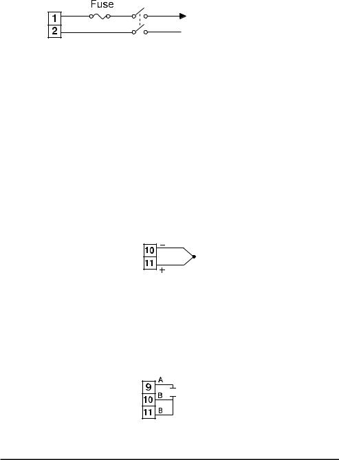
POWER SUPPLY
The controller is supplied to operate on either 90-264V AC or 2032V AC/DC. Check that the supply voltage corresponds to that indicated on the product label before connecting power to the controllers.
1A
L
90~264V AC or N  20-32V
 AC/DC
AC/DC


Power Supply Connections
This equipment is designed for installation in an enclosure which provides adequate protection against electric shock. The enclosure must be connected to earth ground.
THERMOCOUPLE INPUT
Thermocouple input connections are shown in the illustration below. The thermocouple extension wire must be of proper type and gauge, and should be run in a conduit, separate from any
power wiring. The resistance of the entire run should not exceed 100Ω.
Thermocouple Input Connections
Pt100 Ohm RTD INPUT
RTD connections are shown in the illustration below with the compensating lead connected to terminal 11. For two-wire RTD inputs, terminals 10 and 11 should be linked.

 Pt100
Pt100
RTD input Connections
8
DC LINEAR INPUT
DC linear voltage and current input connections are shown below.
VDC
mADC
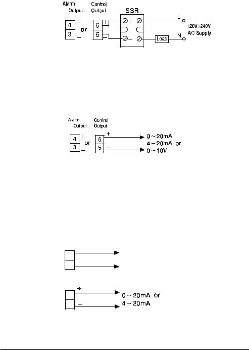
RELAY OUTPUT DIRECT DRIVE
The illustration below shows connections for using the internal relay to drive a small load. The current should not exceed 3 amps.
Relay Direct Drive Connections
RELAY OUTPUT CONTACTOR DRIVE
The illustration below shows connections for using an external relay to drive heavier loads.
Relay Contactor Drive Connections
9
DC PULSE (SOLID-STATE RELAY DRIVE) OUTPUT
Controllers fitted with the DC pulse output produce a time-propor- tional non-isolated pulse voltage (0-24V nominal, output impedance 660Ω ). The connections are shown in the illustration below.
|
/ |
2nd |
1 |
Pulsed DC output Connections
DC LINEAR OUTPUT
There are three types of linear output modules that can be selected for the output. The connections are shown in the illustration below.
|
/ |
2nd |
1 |
Linear DC output Connections
RS-485 COMMUNICATIONS/ANALOG RETRANSMISSION
RS-485 serial communications or Analog retransmission of process variable, setpoint, or manipulated variable can be selected as an optional feature. The connections are shown in the illustration below.
TX1
13
14 TX2
RS-485 Communications
13
14
Analog retransmission
10
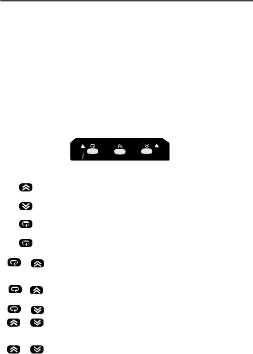
NEGOTIATING THE CN491A MENU
When the controller is powered up it automatically displays the Process Variable (PV).
From the Process Variable (PV) display you can easily:
Press either the  or
or  key momentarily to view set-point. or
Press the  key momentarily to enter the Primary Program Menu. or
Press the  key and the
  key simultaneously to enter the Tool Program Menu.
|
|
|
|
CN491 |
|
|
|
|
|
||
|
|
|
|
|
|
|
TOUCH KEYS |
FUNCTION |
DESCRIPTION |
||
|
|
Up key |
Press to select digit to change. Press and hold |
||
|
|
|
|
to increase value for parameter |
|
|
|
|
|
|
|
|
|
Down key |
Press to select digit to change. Press and hold |
||
|
|
|
|
to decrease value for parameter |
|
|
|
|
|
|
|
|
|
Scroll key |
Press to select parameter in direct sequence |
||
|
|
|
|
or to select tool program parameters |
|
|
|
|
|
|
|
|
|
Long scroll/ |
Use to select protected parameters in higher |
||
|
press for 3.2 seconds |
Enter key |
security level or to actuate selected tool program |
||
|
|
|
|
|
|
|
& |
Reverse scroll/ |
Use to select parameter in reverse sequence or |
||
|
|
Calibration |
to verify display accuracy for input types during |
||
|
|
Verification |
calibration |
||
|
|
|
|
|
|
|
& |
Lock key |
Use to disable keypad operation to protect |
||
|
press for 3.2 seconds |
|
|
parameters |
|
|
& |
Tool program key |
Press to select tool program in sequence |
||
|
& |
Reset/Exit key |
Press to unlock keypad operation, to reset |
||
|
|
|
|
display, to exit tool program, or to end autotune |
|
|
|
|
|
and manual control execution. |
|
|
|
|
|
|
|
|
& |
Autotune key |
Hold both keys for 3.2 seconds then release to |
||
|
press for 3.2 seconds |
|
|
start autotune. |
|
|
|
|
|
|
|
|
|
|
|
|
|
11
Loading...