


MADE IN


 User’sGuide
NOTE:
Model is factory set for type ___________
input only.
Serial No. _____________
Shop online at
omega.com e-mail: info@omega.com For latest product manuals: omegamanual.info
CSC32 SERIES
Mini Benchtop Controller

|
OMEGAnet® Online Service |
|
Internet e-mail |
|
|
|
omega.com |
|
info@omega.com |
|
|
|
|
|
|
|
Servicing North America: |
||
U.S.A.: |
One Omega Drive, P.O. Box 4047 |
|
||
ISO 9001 Certified |
Stamford, CT 06907-0047 |
|
||
|
|
TEL: (203) 359-1660 |
|
|
|
|
FAX: (203) 359-7700 |
|
|
|
|
e-mail: info@omega.com |
|
|
Canada: |
976 Bergar |
|
||
|
|
Laval (Quebec) H7L 5A1, Canada |
|
|
|
|
TEL: (514) 856-6928 |
|
|
|
|
FAX: (514) 856-6886 |
|
|
|
|
e-mail: info@omega.ca |
|
|
For immediate technical or application assistance:
U.S.A. and Canada:
Mexico:
Sales Service: 1-800-826-6342/1-800-TC-OMEGA®
Customer Service: 1-800-622-2378/1-800-622-BEST®
Engineering Service: 1-800-872-9436/1-800-USA-WHEN®
En Espan˜ol: (001) 203-359-7803 e-mail: espanol@omega.com FAX: (001) 203-359-7807 info@omega.com.mx
Servicing Europe:
Czech Republic: Frystatska 184, 733 01 Karviná, Czech Republic
TEL: +420 (0)59 6311899
FAX: +420 (0)59 6311114
Toll Free: 0800-1-66342 e-mail: info@omegashop.cz
Germany/Austria: Daimlerstrasse 26, D-75392 Deckenpfronn, Germany TEL: +49 (0)7056 9398-0
FAX: +49 (0)7056 9398-29
Toll Free in Germany: 0800 639 7678 e-mail: info@omega.de
United Kingdom: One Omega Drive, River Bend Technology Centre ISO 9001 Certified Northbank, Irlam, Manchester
M44 5BD United Kingdom
TEL: +44 (0)161 777 6611
FAX: +44 (0)161 777 6622
Toll Free in United Kingdom: 0800-488-488 e-mail: sales@omega.co.uk
It is the policy of OMEGA Engineering, Inc. to comply with all worldwide safety and EMC/EMI regulations that apply. OMEGA is constantly pursuing certification of its products to the European New Approach Directives. OMEGA will add the CE mark to every appropriate device upon certification.
The information contained in this document is believed to be correct, but OMEGA accepts no liability for any errors it contains, and reserves the right to alter specifications without notice.
WARNING: These products are not designed for use in, and should not be used for, human applications.

|
|
CSC32 Series Mini Benchtop Controller |
Table of |
|
|
Contents |
|
|
|
|
|
Section |
|
|
Page |
Section 1 |
Introduction ................................................................................. |
1-1 |
|
|
1.1 |
Precautions ............................................................................. |
1-1 |
|
1.2 |
Safety Warnings and I.E.C. Symbols ................................... |
1-1 |
|
1.3 Statement on CE Marking .................................................... |
1-2 |
|
|
1.4 Available Models .................................................................... |
1-2 |
|
Section 2 |
Installation ................................................................................... |
2-1 |
|
|
2.1 |
Unpacking and Inspection ................................................... |
2-1 |
|
2.2 Power Connection ................................................................. |
2-2 |
|
|
|
2.2.1 108-125 VAC ~, 50/60 Hz Model ............................... |
2-2 |
Section 3 |
Operation ...................................................................................... |
3-1 |
|
|
3.1 |
Front Panel Controls and Indicators ................................... |
3-1 |
|
3.2 Rear Panel Connection (Thermocouple Models) .............. |
3-1 |
|
|
3.3 Rear Panel Connection (RTD, MV, MA Models) ............... |
3-2 |
|
|
3.4 |
Controller Settings and Programming ................................ |
3-2 |
|
|
3.4.1 Input Type Setup .......................................................... |
3-3 |
|
|
3.4.2 Output Type Setup ...................................................... |
3-3 |
|
|
3.4.3 Changing the Temperature/Process Setpoint ......... |
3-3 |
|
|
3.4.4 All Other Settings and Programming ....................... |
3-3 |
Section 4 |
RS232/485 Communication ....................................................... |
4-1 |
|
|
4.1 |
Cable Connections ................................................................. |
4-1 |
|
4.2 |
Software .................................................................................. |
4-1 |
|
4.3 |
Settings/Programming ......................................................... |
4-1 |
Section 5 |
Maintenance ................................................................................ |
5-1 |
|
|
5.1 |
Calibration .............................................................................. |
5-1 |
|
5.2 |
Cleaning .................................................................................. |
5-1 |
|
5.3 |
Fuse Replacement .................................................................. |
5-1 |
|
|
5.3.1 108 to 125 Vac ~, 50/60 Hz Model ............................. |
5-1 |
Section 6 |
Troubleshooting .......................................................................... |
6-1 |
|
|
6.1 |
Troubleshooting ..................................................................... |
6-1 |
Section 7 |
Specifications .............................................................................. |
7-1 |
|
|
7.1 |
Benchtop Configuration ....................................................... |
7-1 |
|
7.2 |
Controller Model CN9522 Specifications ........................... |
7-1 |
i

List of
Figures CSC32 Series Mini Benchtop Controller
List of Figures
Figure Description |
Page |
|
1. |
I. E. C. Symbols ......................................................................................... |
1-1 |
2a. |
Front Panel (108 to 125 Vac Models)....................................................... |
3-1 |
2b. |
Rear Panel (Thermocouple Models) ...................................................... |
3-2 |
2c. |
Rear Panel (RTD, MV and MA Models) ................................................ |
3-2 |
3. |
Communications Cable Connections .................................................... |
4-1 |
ii
Introduction 1
Section 1 - Introduction
Your CSC32 series Benchtop controller is ideal for laboratory use and applications requiring portable temperature or process control. Pre-wired input and output receptacles on the rear panel enable quick and easy connections to main ac power, signal input, control output and two way digital communications. These controllers are factory configured and calibrated for a dedicated input type by model number. It is important that you read this manual and controller manual number M2897 completely and follow all safety precautions in both manuals before operating this unit.
1.1Precautions
•Follow all safety precautions and operating instructions outlined in this manual.
•Keep out of reach of all children.
•Do not operate in flammable or explosive environments.
•Never operate with a power cord other than the one provided with your unit.
•Remove and/or disconnect main power cord before attempting any maintenance or fuse replacement.
•Do not connect and/or operate this unit to a non-grounded, non-polarized outlet or power source.
•Do not reconfigure the input type factory set in the controllers program. Incorrect readings and/or control may result.
NOTE:
There are no user serviceable parts inside your |
Attempting to repair or service your unit may void |
|
your warranty. |
|
|
|
|
|
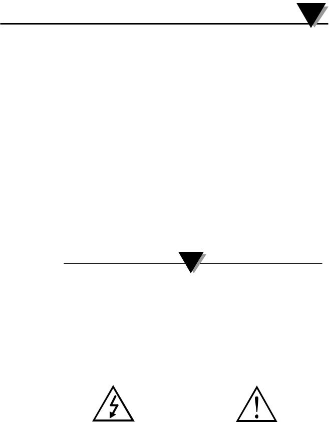
1.2Safety Warnings and IEC Symbols
This device is marked with international safety and hazard symbols in accordance with IEC 1010. It is important to read and follow all precautions and instructions in this manual before operating or commissioning this device as it contains important information relating to safety and EMC. Failure to follow all safety precautions may result in injury and or damage to your calibrator. Use of this device in a manor not specified by the manufacturer may impair protection provided within the unit.
Caution, risk of electric shock |
Caution, refer to accompanying documents |
Figure 1. IEC Symbols
1-1
 Loading...