


User’s Guide
Shop on line at
 ®
®
®
www.omega.com e-mail: info@omega.com www.omega.com/software For latest product manuals www.omegamanual.info
MICROMEGA®
CN77000 Series Controller

|
® |
|
® |
Servicing North America: |
|
USA: |
One Omega Drive, P.O. Box 4047 |
ISO 9001 Certified |
Stamford CT 06907-0047 |
|
TEL: (203) 359-1660 |
|
FAX: (203) 359-7700 |
|
e-mail: info@omega.com |
Canada: |
976 Bergar |
|
Laval (Quebec) H7L 5A1 |
TEL: (514) 856-6928 FAX: (514) 856-6886 e-mail: info@omega.ca
For immediate technical or application assistance:
USA and Canada: |
Sales Service: 1-800-826-6342 / |
|
1-800-TC-OMEGA® |
|
Customer Service: 1-800-622-2378 / |
|
1-800-622-BEST® |
|
Engineering Service: 1-800-872-9436 / |
|
1-800-USA-WHEN® |
Mexico and |
TEL: (001)800-TC-OMEGA® |
Latin America: |
FAX: (001) 203-359-7807 |
|
En Español: (001) 203-359-7803 |
|
e-mail: espanol@omega.com |
OMEGAnet® On-Line Service |
|
Internet e-mail |
|
www.omega.com |
|
info@omega.com |
|
|
|
|
|
|
Servicing Europe: |
||
Benelux: |
Postbus 8034, 1180 LA Amstelveen, The Netherlands |
||
|
TEL: +31 20 3472121 |
|
|
|
FAX: +31 20 6434643 |
|
|
|
Toll Free in Benelux: 0800 0993344 |
||
|
e-mail: sales@omegaeng.nl |
||
Czech Republic: |
Frystatska 184, 733 01 Karviná |
||
|
TEL: +420 59 6311899 |
|
|
|
FAX: +420 59 6311114 |
|
|
|
e-mail: info@omegashop.cz |
||
France: |
11, rue Jacques Cartier, 78280 Guyancourt |
||
|
TEL: +33 1 61 37 29 00 |
|
|
|
FAX: +33 1 30 57 54 27 |
|
|
|
Toll Free in France: 0800 466 342 |
||
|
e-mail: sales@omega.fr |
|
|
Germany/Austria: |
Daimlerstrasse 26, D-75392 Deckenpfronn, Germany |
||
|
TEL: +49 7056 9398-0 |
|
|
|
FAX: +49 7056 9398-29 |
|
|
|
Toll Free in Germany: 0800 639 7678 |
||
|
e-mail: info@omega.de |
|
|
United Kingdom: |
One Omega Drive |
|
|
ISO 9002 Certified |
River Bend Technology Centre |
||
|
Northbank, Irlam Manchester M44 5BD United Kingdom |
||
TEL: +44 161 777 6611
FAX: +44 161 777 6622
Toll Free in England: 0800 488 488 e-mail: sales@omega.co.uk
It is the policy of OMEGA to comply with all worldwide safety and EMC/EMI regulations that apply. OMEGA is constantly pursuing certification of its products to the European New Approach Directives. OMEGA will add the CE mark to every appropriate device upon certification.
The information contained in this document is believed to be correct, but OMEGA Engineering, Inc. accepts no liability for any errors it contains, and reserves the right to alter specifications without notice.
WARNING: These products are not designed for use in, and should not be used for, patient-connected applications.
This device is marked with the international caution symbol. It is important to read the Setup Guide before installing or commissioning this device as the guide contains important information relating to safety and EMC.

To Order Model CN77000 SERIES CONTROLLER (Specify Model Number)
PROCESS CONTROLLER, DUAL DISPLAY FOR THERMOCOUPLE, RTD, VOLTAGE OR CURRENT INPUTS IN A 1/16 DIN CASE
Model No. Description
CN77 Dual displays for simultaneous display of measured value and setpoint. Selectable preset tune, adaptive tune, autotune, PID, PI, PD control modes. The dual control outputs can be configured for a variety of control and alarm applications such as heat, heat/cool, heat/alarm, cool or cool/alarm. The ramp to setpoint feature allows the user to define the rate of rise to setpoint, minimizing thermal shock to the load during start-up. Maximum ramp time 99.59 (HH.MM), Soak: 00.00 to 99.59 (HH.MM),Damping: 1 to 8 in unit steps. Input types J,K,T,E,R,S,B,N,J-DIN°C, RTD 100Ω 0.00385, 100Ω & 1kΩ 0.00392, 0 to 20 mA, 4 to 20 mA, 0 to 100mV, 0 to 1V, 0 to 10Vdc. Alarm 1 output includes SPST relay, 3A @ 120Vac, 3A @ 240Vac.
NOTE: The Controller must be ordered completely configured. Options are not field installable.
[ ] |
CASE TYPE |
|
R3 |
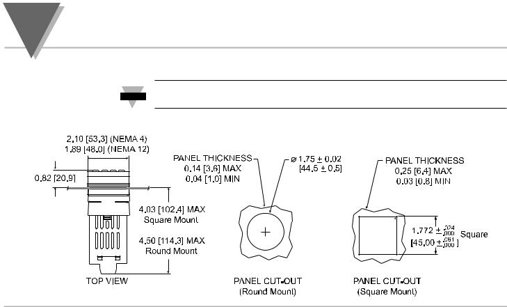
NEMA 1, |
1.89 x1.89" (48 x 48mm) bezel and 1.75" ROUND cutout |
R5 |
NEMA 1, |
2.1 x 2.1" bezel and 1.75” ROUND cutout |
3NEMA 12 bezel for 1/16 DIN panel cutout 45mm x 45mm (1.772 x 1.772")
5NEMA 4 bezel for 1/16 DIN panel cutout 45mm x 45mm (1.772 x 1.772")
[ ] |
CONTROL OUTPUT #1 (Direct or Reverse Acting) |
2Solid State Relay SSR : 1A @ 120/240Vac continuous
3Relay: Form “C” 5A @ 120Vac, 3A @ 240Vac
4Pulsed 10Vdc @20mA (for use with external SSR)
5Non-Isolated 1 to 10Vdc or 0-20mA @500Ω max
[ ] |
CONTROL OUTPUT #2 (Direct or Reverse Acting) |
0Insert “0” if second output is not desired
2Solid State Relay SSR: 1A @ 120/240Vac continuous
3Relay: Form “C” 5A @ 120Vac, 3A @ 240Vac
4Pulsed 10Vdc @20mA (use for external SSR)
Model No. Description cont.
[ ] |
OPTIONAL OUTPUTS |
*none (no entry required)
-A2 |
SPST relay, 3A@ 120Vac, 3A @ 240Vac (Alarm 2) |
-C2 |
Isolated RS232, 300 to 19.2k baud |
-C4 |
Isolated RS485, 300 to 19.2k baud |
-PV |
Isolated Analog Output |
-RSP |
Remote Setpoint Selection |
[ ] |
POWER SUPPLY |
*90 to 240 Vac/dc, 50 to 400Hz (no entry required)
NEMA 1/UL Type 1: Intended for indoor use, to provide a degree of protection against contact with the enclosed equipment and against limited amount of falling dirt.
NEMA 4/UL Type 4: Intended for indoor use, to provide a degree of protection against splashing water, windblown dust and rain, and hose directed water and undamaged by the formulation of ice on the enclosure. Testing-Hosedown: Enclosure is subjected to a stream of water from a hose which has a 1" diameter nozzle and which delivers at least 65 gallons per minute from a distance of 10 to 12 feet for a minimum of 5 minutes.
NEMA 12/UL Type 12: Intended for indoor use, to provide a degree of protection against circulating dust, falling dirt, and dripping non-corrosive liquids. Testing-Drip: Enclosure is subjected to a drip pan which produces both splashing and dripping. Testing-Atomized Water: Enclosure is subjected to a spray of atomized water by using a nozzle that produces a 3" round diameter spray, 12" from enclosure. The air pressure is at 30psi.
For harsh environments, we recommend installation of the controller for square panel cutouts.
Ordering Examples:
1.) CN77R322-C2 is a NEMA 1 bezel case with 1.75 inch round hole mounting adaptor, dual SSR control outputs and RS232 communications output. 2.) CN77330 is a NEMA 12 bezel case with 1/16 DIN mounting and single Relay control output.
3.) CN77544-A2 is a NEMA 4 bezel case with 1/16 DIN mounting, dual pulse control outputs, and a SPST 3A Alarm relay.

NOTES

TABLE OF CONTENTS
Part 1: Introduction |
|
|
1.1 |
Safety Considerations ......................................................................... |
1 |
1.2 |
Before You Begin.................................................................................. |
2 |
Part 2: Setup |
|
|
2.1 |
Mounting the Controller....................................................................... |
4 |
2.2 |
Front Panel View .................................................................................. |
7 |
|
Front Panel Annunciators....................................................................... |
7 |
2.3 |
Rear Panel View.................................................................................... |
8 |
|
Rear Panel Connector Labels ................................................................ |
9 |
2.4 |
Mechanical Installation ...................................................................... |
10 |
|
Dip Switch Configuration ...................................................................... |
10 |
|
Dip Switch Settings............................................................................... |
11 |
2.5 |
Electrical Installation ......................................................................... |
12 |
|
Input Connection Examples ................................................................. |
13 |
2.5.1 |
Thermocouple....................................................................................... |
13 |
2.5.2 |
Two/Three/Four Wire RTD ................................................................... |
14 |
2.5.3 |
Process Current ................................................................................... |
15 |
2.5.4 |
Process Voltage ................................................................................... |
15 |
i

TABLE OF CONTENTS |
|
|
Part 3: Operation: Configuration Mode |
|
|
3.1 |
Introduction........................................................................................ |
16 |
|
Turning Your Controller on for the First Time ............................................. |
16 |
|
Function in Configuration Mode................................................................ |
17 |
3.2 |
Menu Configuration........................................................................... |
18 |
|
ID Number ............................................................................................. |
19 |
|
Set Points .............................................................................................. |
20 |
|
Input Type (Thermocouple)...................................................................... |
24 |
|
Input Type (RTD) .................................................................................... |
25 |
|
Input Type (RTD Value)........................................................................... |
26 |
|
Input Type (Process)............................................................................... |
27 |
|
Reading Configuration............................................................................. |
29 |
|
Alarm 1.................................................................................................. |
33 |
|
Alarm 2.................................................................................................. |
36 |
|
Loop Break Alarm................................................................................... |
38 |
|
Output 1 ................................................................................................ |
42 |
|
Output 2 ................................................................................................ |
52 |
|
Ramp & Soak......................................................................................... |
58 |
3.3 |
Available Options............................................................................... |
60 |
|
Analog Output Option.............................................................................. |
61 |
|
Communication Option............................................................................ |
64 |
ii

TABLE OF CONTENTS |
|
Configuration Mode Cont. |
|
Command Formats ........................................................................................................... |
72 |
Reading Scale ............................................................................................................................. |
86 |
Reading Offset ................................................................................................................. |
87 |
Remote Setpoint Option .................................................................................................... |
88 |
Part 4 Specifcations......................................................................................... |
91 |
List of Figures |
|
Figure 2.1 a. — Mounting the Square Mount Controller ................................................................. |
5 |
Figure 2.1 b. — Mounting the Round Mount Controller .................................................................. |
6 |
Figure 2.2 — Front Panel Display ................................................................................................... |
7 |
Figure 2.3 — Typical Rear Connector Label and Possible Labels of Different Models .................. |
8 |
Figure 2.4 — Dip Switch Location................................................................................................. |
10 |
Figure 2.5.1 — Power Wiring Hookup........................................................................................... |
12 |
Figure 2.5.2 — Thermocouple Wiring Hookup.............................................................................. |
13 |
Figure 2.5.3 — Two-wire RTD Hookup, Three-Wire RTD Hookup, Four -Wire RTD Hookup ...... |
14 |
Figure 2.5.4 — Process Current Wiring Hookup........................................................................... |
15 |
Figure 2.5.5 — Process Voltage Wiring Hookup........................................................................... |
15 |
Figure 3.1 — Flowchart for ID and Set Point Menus .................................................................... |
18 |
Figure 3.2 — Flowchart for Input Type.......................................................................................... |
23 |
Figure 3.3 — Flowchart for Reading Configuration....................................................................... |
28 |
iii

TABLE OF CONTENTS
List of Figures Cont. |
|
|
Figure 3.4 — Flowchart for Alarm 1 and Alarm 2.......................................................................... |
32 |
|
Figure 3.5 — Flowchart for Loop Break ........................................................................................ |
37 |
|
Figure 3.6 |
— Flowchart for Output 1............................................................................................. |
41 |
Figure 3.7 |
— Flowchart for Output 2............................................................................................. |
51 |
Figure 3.8 |
— Flowchart for Ramp & Soak .................................................................................... |
57 |
Figure 3.9 |
— Flowchart for Analog Output Option ........................................................................ |
61 |
Figure 3.10 — Flowchart for Communication Option.................................................................... |
64 |
|
Figure 3.11 — Flowchart for Remote Setpoint.............................................................................. |
88 |
|
List of Tables |
|
|
Table 3.1 — Communication Commands..................................................................................... |
72 |
|
Table 3.2 — Command Letters and Index .................................................................................. |
76 |
|
iv

part
INTRODUCTION 1
1.1 Safety Considerations
This device is marked with the international caution symbol. It is important to read this manual before installing or commissioning this device as it contains important information relating to Safety and EMC (Electromagnetic Compatibility).
This instrument is a panel mount device protected in accordance with Class I of EN 61010 (115/230 AC power connections). Installation of this instrument should be done by qualified personnel. In order to ensure safe operation, the following instructions should be followed.
This instrument has no power-on switch. An external switch or circuit-breaker shall be included in the building installation as a disconnecting device. It shall be marked to indicate this function, and it shall be in close proximity to the equipment within easy reach of the operator. The switch or circuit-breaker shall meet the relevant requirements of IEC 947–1 and IEC 947-3 (International Electrotechnical Commission). The switch shall not be incorporated in the main supply cord.
Furthermore, to provide protection against excessive energy being drawn from the main supply in case of a fault in the equipment, an overcurrent protection device shall be installed.
•Do not exceed voltage rating on the label located on the top of the instrument housing.
•Always disconnect power before changing signal and power connections.
•Do not use this instrument on a work bench without its case for safety reasons.
•Do not operate this instrument in flammable or explosive atmospheres.
•Do not expose this instrument to rain or moisture.
•Unit mounting should allow for adequate ventilation to ensure instrument does not exceed operating temperature rating.
•Use electrical wires with adequate size to handle mechanical strain and power requirements. Install without exposing bare wire outside the connector to minimize electrical shock hazards.
EMC Considerations
•Whenever EMC is an issue, always use shielded cables.
•Never run signal and power wires in the same conduit.
•Use signal wire connections with twisted-pair cables.
•Install Ferrite Bead(s) on signal wires close to the instrument if EMC problems persist.
Failure to follow all instructions and warnings may result in injury!
1

part
1INTRODUCTION
Customer Service
Inspecting Your Shipment
Manuals, Software:
1.2 Before You Begin
If you need assistance, please contact the nearest Customer Service Department, listed in this manual.
Remove the packing slip and verify that you have received everything listed.
Inspect the container and equipment for signs of damage as soon as you receive the shipment. Note any evidence of rough handling in transit. Immediately report any damage to the shipping agent. The carrier will not honor damage claims unless all shipping material is saved for inspection. After examining and removing the contents, save the packing material and carton in the event reshipment is necessary.
The latest Operation and Communication Manual as well as free configuration software are available from the website listed in this manual or on the CD-ROM enclosed with your shipment.
For first-time users: Refer to the QuickStart Manual for basic operation and set-up instructions.
If you have the Serial Communications Option you can easily configure the controller on your computer or on-line.
2
part
INTRODUCTION 1
TO DISABLE OUTPUTS
Standby mode is useful during setup of the controller or when maintenance of the system is necessary. When the controller is in standby, it remains in the ready condition but all outputs are disabled. This allows the system to remain powered and ready to go.
When the controller is in "RUN" Mode, push ENTER twice to disable all outputs and alarms.
It is now in "STANDBY" Mode. Push ENTER once more to resume "RUN" Mode.
PUSH ENTER TWICE to disable the system during an EMERGENCY.
3
part
2SETUP
2.1 Mounting the Controller
If necessary, the rear connector assembly may be removed from the main case for
Note
wiring (see Figure 2.1a for Square Mount, Figure 2.1b for Round Mount).
R 0.06 [1.6]
[1.6]
4
|
|
part |
Square Mount |
SETUP |
2 |
|
|
|
Square Mount Micro Controller Mounting Instructions |
|
|
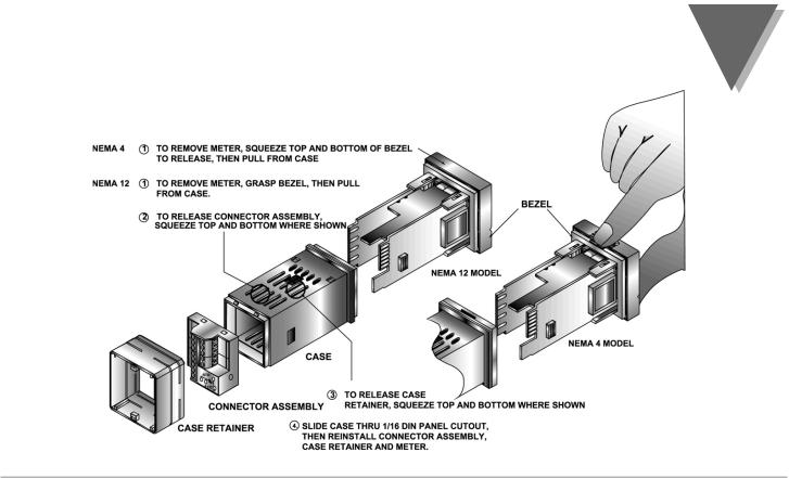
Figure 2.1a — Mounting the Square Mount Controller
5
part |
|
|
2 |
SETUP |
Round Mount |
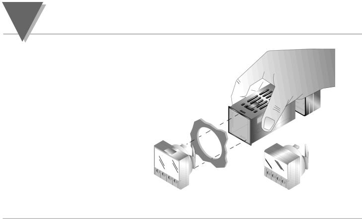
Round Mount Micro Controller Mounting
1.Separate the display from the meter by squeezing the unplugging the cable from the meter.
2.Slide the retainer over the rear of the case, but do not case.
3.Pass the cable (from the display) thru a 1 3/4" diameter panel and connect to the meter (take care to center connector on the mating pins). While squeezing the press the display and meter squarely together
until they connect.
4.Check the display and gasket for proper alignment, then slide the retainer tight against the backside of the mounting panel.
Figure 2.1b — Mounting the Round Mount Controller
6
part
SETUP 2
2.2. |
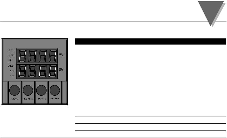
Figure 2.2 Front Panel Display
Front Panel View
Front Panel Annunciators
SP1 |
OUT1/Setpoint 1 indicator. |
SP2 |
OUT2/Setpoint 2 indicator. |
|
|
AL1 |
Alarm 1 indicator. |
|
|
AL2 |
Alarm 2 indicator. |
|
|
°C |
°C unit indicator. |
|
|
°F |
°F unit indicator. |
|
|
PV |
Upper display shows the Process Value |
|
|
SV |
Lower display shows the Setpoint Value |
|
|
MENU |
Changes display to Configuration Mode and advances thru menu items* |
|
|
/MAX Used in program mode and peak recall*
/MIN Used in program mode and valley recall*
ENTER Accesses submenus in Configuration Mode and stores selected values*
* See Part 3 Operation:Configuration Mode
7

part
2SETUP
2.3.Rear Panel View
Figure 2.3 Typical Rear Connector Label and Possible Labels of Different Models
8

part
SETUP 2
Rear Panel Connector Labels |
|
|
POWER |
AC Power Connector: All models |
|
|
|
|
INPUT |
Input Connector: All models |
|
|
TC, PR (Process) |
|
|
RTD |
|
|
|
|
ALARM 1 |
ALARM 1 relay SPST, programmable: All models |
|
|
|
|
OUTPUT 1 |
Control Output 1: Based on one of the following models. |
|
|
Relay SPDT |
Voltage and Current |
|
Solid State Relay |
Pulse |
|
|
|
OUTPUT 2 |
Control Output 2: Based on one of the following models: |
|
|
Relay SPST Normally Open |
|
|
Solid State Relay |
|
|
Pulse |
|
|
|
|
OPTION |
Based on one of the following models: |
|
|
RS-232C |
Isolated Analog Out |
|
RS-485 |
Alarm 2 Relay SPST, programmable |
|
|
Remote Setpoint |
|
|
|
9
part
2SETUP
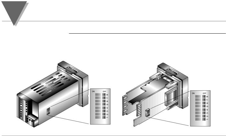
2.4. Mechanical Installation
Dip Switch
Configuration
The settings of the DIP switch must be verified or set to comply with your selection at the Input/Type menu (see Section 3.0 for Input/Type). The DIP switch is accessible through an opening on the side of the case or may be accessed by removing the controller from the case, see Section 2.1 for instructions. Locate the dip switch (see Figure 2.4) and set the switches according to the following tables.
Unit installed in case. |
Unit removed from case. |
opening in case
Figure 2.4 Dip Switch Location — switch settings are shown in OFF position
10
part
SETUP 2
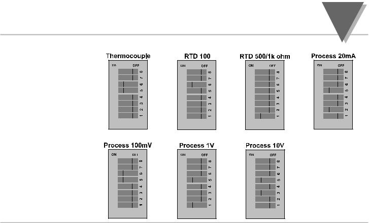
Dip Switch Settings
11
part
2SETUP
For SSR wiring hook-up examples, refer to Specification Section. |
2.5. Electrical Installation |
|
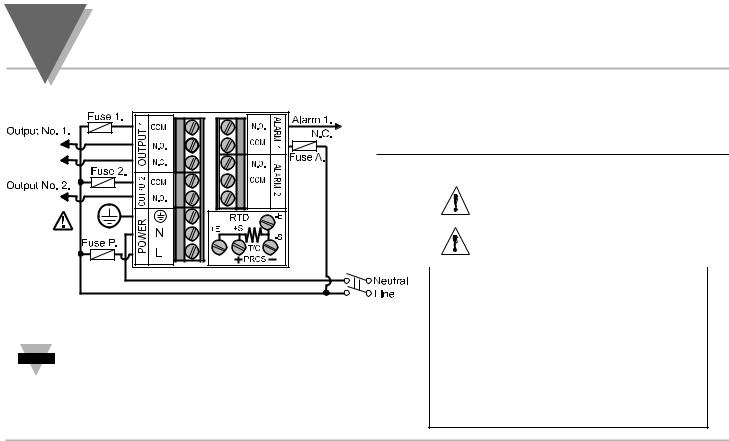
POWER CONNECTION EXAMPLES
The figure below shows the power wiring hookup.
Figure 2.5.1 Power Wiring Hookup
The Safety European Standard EN61010-1 for measurement, control, and laboratory Note equipment requires that fuses must be specified based on IEC127. This standard
specifies for a Time-lag fuse, the letter code “T”. The above recommended fuses are of the type IEC127-2-sheet III. Be aware that there are significant differences between the requirements listed in the UL 248-14/CSA 248.14 and the IEC 127 fuse standards. As a result, no single fuse can carry all approval listings. A 1.0 Amp IEC fuse is approximately equivalent to a 1.4 Amp UL/CSA fuse. It is advised to consult the manufacturer’s data sheets for a cross-reference.
Use copper conductors only for power connections
The Protective Conductor terminal must be connected for safety reasons.
Fuse |
Connector |
Output Type |
115 Vac |
230 Vac |
Fuse 1 |
Output 1 |
Relay |
5 A(T) |
3 A(T) |
|
|
|
|
|
Fuse 2 |
Output 1 |
Relay |
5 A(T) |
3 A(T) |
|
|
|
|
|
|
|
SSR |
0.5 A(T) |
0.5 A(T) |
|
|
|
|
|
Fuse P |
Power |
N/A |
100 mA(T) |
100 mA(T) |
Fuse A |
Alarm 1/2 |
Relay |
3 A(T) |
3 A(T) |
Note: Values shown are minimum recommendations for the protection of the controller. For a specific load, consult the respected electrical specifications to select a suitable fuse.
12
|
|
|
|
|
part |
|
|
|
|
SETUP |
2 |
|
INPUT CONNECTION EXAMPLES |
|
|
||
2.5.1. Thermocouple |
The figure below shows the wiring hookup for any thermocouple type. For |
||||
|
example, for Type K hookup, connect the yellow wire to the + (+S) Terminal and |
||||
|
the red wire to the – (–S) Terminal. When configuring your controller, select |
||||
|
Thermocouple and Thermocouple type in the Input Type menu |
(see part 3). |
|||
|
TYPE |
Input Connector |
Jacket (external insulation) |
||
|
|
Terminal 1 (-) |
Terminal 2 (+) |
Extension |
Grade |
|
J |
Red |
White |
dark-Brown |
Black |
|
K |
Red |
Yellow |
dark-Brown |
Yellow |
|
T |
Red |
Blue |
dark-Brown |
Blue |
|
E |
Red |
Purple |
dark-Brown |
Purple |
|
N |
Red |
Brown |
dark-Brown |
Brown |
|
R |
Red |
Black |
- |
Green |
|
S |
Red |
Black |
- |
Green |
|
B |
Red |
Black |
- |
Black |
Figure 2.5.2 Thermocouple Wiring Hookup
13
part
2SETUP
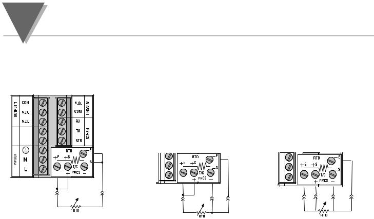
2.5.2. Two/Three/Four-Wire RTD
Figure 2.5.3
The figures below show the input connections and input connector jumpers required to hookup a 2, 3 or 4-wire RTD.
The two-wire connection is the simplest method, but does not compensate for leadwire temperature change and often requires calibration to cancel lead-wire resistance offset.
The three-wire connection works best with RTD leads closely equal in resistance. The controller measures the RTD, plus upper and lower lead drop voltage and then subtracts twice the measured drop in the lower supply current lead producing excellent lead-resistance cancellation for balanced measurements.
The four-wire RTD hookup is applicable to unbalanced lead resistance and enables the controller to measure and subtract the lead voltage which produces the best lead-resistance cancellation.When configuring your controller, select RTD type and RTD value in the Input Type Menu (see part 3).
|
|
|
|
|
|
|
|
|
|
|
|
|
|
|
|
|
|
|
|
|
|
|
|
|
|
|
|
|
|
|
|
|
|
|
|
|
|
|
|
|
|
|
|
|
|
|
|
|
|
|
|
|
|
|
|
|
|
|
|
|
|
|
|
|
|
|
|
Two-Wire RTD Hookup |
|
|
|
|
|
|
|
|
|
|
|
|
|
|
|
|
|
|
|
|
|
|
|
|
|
|
|||||||
|
|
|
|
|
|
|
|
|
|
|
|
|
|
|
|
|
|
|
|
|
|
|
|
|
|
||||||||
|
|
|
|
|
|
|
|
|
|
|
|
|
|
|
|
|
|
|
|
|
|
|
|
|
|
||||||||
Three-Wire RTD Hookup |
|
Four-Wire RTD Hookup |
|||||||||||||||||||||||||||||||
14
|
|
part |
|
SETUP |
2 |
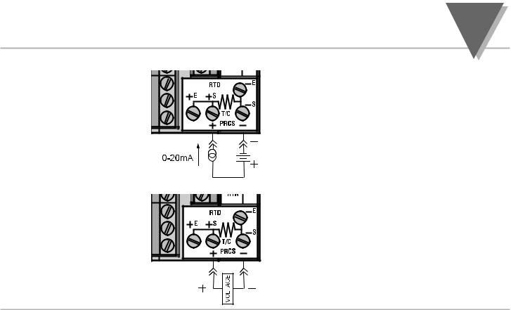
2.5.3. Process Current |
The figure shows the wiring hookup for Process |
|
|
Current 0 - 20 mA. |
|
|
When configuring your controller, select |
|
|
Process type in the Input Type menu |
|
|
(see part 3). |
|
|
Figure 2.5.4 Process Current Wiring Hookup |
|
2.5.4. Process Voltage
The figure shows the wiring hookup for
Process Voltage 0 - .1 V, 0 - 1 V, or 0 -10 V.
When configuring your controller, select Process type in the Input Type menu (see part 3).
Figure 2.5.5 Process Voltage Wiring Hookup
15

part
3OPERATION: CONFIGURATION MODE
3.1Introduction
Turning Your Controller On for the First Time
The Controller has two different modes of operation. The first, Run Mode, is used to display values for the process variable, setpoint value and to display or clear peak and valley values. The other mode, Menu Configuration Mode, is used to navigate through the menu options and configure the controller.
Part 3 of this manual will explain the Menu Configuration Mode. For your controller to operate properly, the user must first "program" or configure the menu options in the Menu Configuration Mode.
The Controller becomes active as soon as it is connected to a power source. It has no On or Off button. The Controller will at first flash reset on the PV and software version number on the SV display, and then proceed to the Run Mode.
16

|
part |
OPERATION: CONFIGURATION MODE |
3 |
|
|
Button Function in Configuration Mode
MENU To enter the Configuration Mode, the user must first press MENU. Use this button to advance/navigate to the next setting. The first menu to appear will be "ID Code", if enabled. The user can navigate through all the top level menus by pressing MENU. Selecting an ID of 0000 will allow you to bypass the ID Menu using the MENU button.
/MAX Press this button to scroll through "flashing" selections. When a numerical value is flashing, this button will increase the active digit from "0" to "9". After "9" the display starts at "0" again. The most significant digit may also show a "–" sign. In the Run Mode MAX causes the display to flash the PEAK - press again to return to the PV value.
/MIN Press this button to go back to a previous Top Level Menu item. Press this button twice to reset the controller to the Run Mode.
When a numerical value is flashing, this button will scroll through the digits from left to right digit allowing the user to select the desired digit to modify. In the Run Mode, MIN causes the display to flash the VALLEY - press again to return to the PV value.
ENTER Press this button to access the submenus from a Top Level Menu item. Also, press this button to store a submenu selection or after entering a value — the display will flash a "stored" message to confirm your selection. To reset flashing PEAK or VALLEY press ENTER. In the Run Mode, press ENTER twice to enable Standby Mode with flashing "STBY".
NOTE: Except for Setpoints and the Alarms, modifying any settings of the menu configuration will reset the controller prior to resuming Run Mode.
17
part
3OPERATION: CONFIGURATION MODE
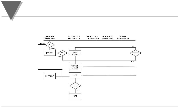
3.2Menu Configuration: Modifying set points will not reset the controller
Figure 3.1 Flowchart for ID and Set Point Menus
18
|
part |
OPERATION: CONFIGURATION MODE |
3 |
ID Number (if enabled)
It is recommended that you put the controller in the Standby Mode
Note
for any configuration change other than setpoints & alarms
Display Action Response
SEE ID OPTION SUBMENU IN THE BREAK LOOP ALARM SECTION FOR ENABLE/DISABLE ID OPTION
Id
C0de
ID.CD
____
CK.ID
1234
STRD 1234
|
ENTERING OR CHANGING YOUR (NON-DEFAULT) ID NUMBER |
||
Press MENU |
1) |
Press MENU, if necessary, until "ID C0DE" prompt appears. |
|
Press ENTER |
2) |
Display advances to "ID CD", if non-default ID code. If default ID code, the menu |
|
|
|
|
will advance to CH.ID with default value i.e. 0000. |
|
|
|
If the ID code is the default value i.e. 0000, press MENU again and the menu will skip the |
|
|
Note |
|
|
|
|
ID code to Set Point Menu. |
Press MAX & MIN |
3) |
Press MAX to increase digit 0-9. Press MIN to activate next digit (flashing). |
|
|
|
|
Continue to use MAX and MIN to enter your 4-digit ID code. |
Press ENTER |
4) |
If the correct ID code is entered, the menu will display CH.ID, otherwise an error |
|
|
|
|
message will be displayed and the controller will return to the Run Mode. |
Press MENU |
5) |
To leave your ID code Unchanged, press MENU and advance to "SET PoNT" Menu. |
|
or |
|
|
|
Press MAX & MIN |
|
|
To Change your ID code use the MAX and MIN buttons to enter a new ID code. |
Press ENTER |
6) |
Display flashes "STRD" message and advances to the next menu "SET PoNT". |
|
|
|
|
|
To prevent unauthorized tampering with the setup parameters, the controller provides protection by requiring the user to enter the ID code Note before allowing access to subsequent menus. If the ID code entered does not match the ID code stored, the controller responds with an
error message and access to subsequent menus will be denied.
Use numbers that are easy for you to remember. If the ID code is forgotten or lost, call customer service with your serial number to reset the default to "0000".
19

part
3OPERATION: CONFIGURATION MODE
Set Points (if ID Number Enabled)
Display |
Action |
Response |
SET PT
SP1
100.5
STRD 100.5
|
SETPOINT 1 |
|
Press MENU |
1) |
Press MENU, if necessary, until "SET PT" prompt appears. |
Press ENTER |
2) |
Display advances to "SP1", Setpoint 1. |
|
DISPLAY SHOWS PREVIOUS VALUE. 1ST DIGIT FLASHING. |
|
Press MAX |
4) |
Press MAX to increase digit 0-9. |
Press MIN |
5) |
Press MIN to activate next digit (flashing). |
|
6) |
Continue to use MAX and MIN to enter your 4-digit Setpoint 1 value. |
Press ENTER |
7) |
Display flashes "STRD" message only if a change is made, otherwise press MENU to |
|
|
advance to "SP2", Setpoint 2. |
SP2
210.5
STRD 210.5
|
SETPOINT 2 : DISPLAY SHOWS PREVIOUS VALUE. 1ST DIGIT FLASHING. |
|
Press MAX & MIN |
9) |
Use MAX and MIN buttons to enter your 4-digit Setpoint 2 value. |
Press ENTER |
13) |
Display flashes "STRD" message and advances to “Swapping Setpoints” submenu. |
20

|
part |
OPERATION: CONFIGURATION MODE |
3 |
Setpoints cont.
Display |
Action |
Response |
S1.o.1
S1.o.1
OUTPUT REDIRECTION: DISPLAY SHOWS “S1.o.1” AND CURRENT SETTING, “S1.o.1”
OR “S1.o.2”
When “S1.o1.” is selected, Setpoint 1 (and OUT 1 configuration) direct the control output at label “Output 1” and Setpoint 2 (and OUT 2 configuration) direct the control output at label “Output 2.” When “S1.o2.” is selected , Setpoint 1 (and OUT 1 configuration) direct the control output at label “Output 2” and Setpoint 2 (and OUT 2 configuration) direct the control at label “Output 1.”
Summary |
Setting |
Setpoint/Out/LED |
Output Label |
|||
|
S1.o.1 |
1 |
|
|
1 |
|
|
|
|
||||
|
S1.o.2 |
2 |
|
|
2 |
|
|
|
|
||||
|
1 |
|
1 |
|||
|
|
2 |
|
2 |
||
|
Press MAX |
14) |
Press MAX to select the output option. |
|
Press ENTER |
15) |
Press ENTER to make the selection or MENU to advance to “Input Type”. |
|
Always put unit in stand-by before redirecting the outputs, and always perform a reset afterward to ensure proper |
||
Note |
|||
|
operation. With Analog Proportional output option, the following issues need to be considered when redirecting the |
||
output: 1) Current (4-20 mA) output is disabled; 2) %Hi/Lo and SELF setting is moved to Out 2 configuration menu;
3)Control Type and Cycle Time appear in Out 1 and is associated with time proportional control at Output 2;
4)Control Type and Cycle Time setting in Out 2 is disregarded by Analog Proportional output.
21

part
3OPERATION: CONFIGURATION MODE
Set Points (if ID Number Disabled - default)
Display |
Action |
Response |
With ID number disabled and in Run Mode, pressing MENU one time advances the controller to Setpoint 1 setting directly.
|
|
SET POINT 1 |
||
|
Press MENU |
1) |
Press MENU once from Run Mode. |
|
125.5 |
||||
(1 time) |
2) |
Display flashes the first digit of Setpoint 1. |
||
100.5 |
Press MAX |
3) |
Press MAX to set the digit, 0-9. |
|
Press MIN |
4) |
Press MIN to activate the next digit (flashing). |
||
|
||||
|
|
5) |
Repeat step 3 and 4 until all digits are set. |
|
|
Press ENTER |
6) |
Controller stores new setting and returns to Run Mode. |
|
|
125.5 |
|
SET POINT 2 |
|
|
Press MENU |
1) |
Press MENU twice from Run Mode. |
|
|
210.5 |
(2 times) |
2) |
Display flashes the first digit of Setpoint 2. |
|
|
3) |
Follow step 3 to 6 of Setpoint 1 to complete the setting. |
|
|
|
|
||
|
|
|
|
|
125.5
S1.o.1
|
OUTPUT REDIRECTION |
|
Press MENU |
1) |
Press MENU 3 times from Run Mode. |
(3 times) |
2) |
Display flashes “S1.o.1” in the SV window. (See previous page for more details.) |
Press MAX |
3) |
Press MAX to select the output option. |
Press ENTER |
4) |
Press ENTER to make the selection or MENU to advance to “Input Type”. |
22
 Loading...