


Meter with
Computer Display
Digital Pulse Meter
FTB691A through ftb695A
Electronic Water Meters


TABLE OF CONTENTS |
|
English............................................................ |
1 |
Español.......................................................... |
7 |
Deutsch........................................................ |
13 |
Italiano.......................................................... |
19 |
Français........................................................ |
24 |
2.For NPT Fittings wrap all connections with 3 to 4 wraps of thread tape. Make sure the tape does not intrude into the flow path.
3.Attach meter with arrow pointed in the direction of flow.
4.For NPT Fittings - Hand tighten the meter at the housing ends. Do not use a wrench or similar tool to tighten. This can damage the housing.
E N G L I S H
IMPORTANT NOTICE
Use FTB690 Series meters with water and other chemicalscompatiblewithwettedcomponents (see Specifications Section). Do not use to meter fuel or incompatible chemicals. FTB690 Series meters are available with either a local electronic display, or a conditioned signal output module to provide a digital signal to customer interfacing equipment. FTB690 Series meters with computer display measure in gallons or liters. Refer to the Calibration Section for details.
These meters are not legal for trade applications.
FTB690 Series meters are very sensitive to electric noise if operated within one to two inches of some electric motors or other sources of electronic noise.
INSTALLATION
Install your meter in-line either horizontally or vertically or at the end of the hose adjacent to the nozzle. Installation to metal connections is not recommended. Install as follows:
1.Plan to install turbine with a minimum straight pipe length as follows:
–Upstreamfromtheturbine,allowaminimum straight pipe length of 10 times the internal diameter of the turbine.
–Downstream from the turbine, allow a minimum straight pipe length of 5 times the internal diameter of the turbine.
Conditioned Signal Output Module Wiring
This conditioned signal output module can be wired to provide an open collector signal output or 6-volt square wave output.
When installing an FTB690 Series meter, the correctK-factormustbeenteredintothereadout device. You can find the K-factor printed on the turbinebody.AllK-factorsonOmegaflowmeters are calculated in pulses per gallon (PPG).
Open Collector Signal Output
To achieve an open collector signal output, reference Wiring Diagram 1. The terminal block is located on the back side of the module. The module is factory assembled for open collector signal output. Please provide the (820 ohm minimum) resistor, if not supplied by receiving equipment.
Ten feet (3m) of cable is provided with the module. Trim it to desired length or extend it as necessary. Distances up to 5,000 feet (1,524m) canbeachievedforopencollectorsignaloutput.
Square Wave Output
To achieve square wave output, reference Wiring Diagram 2 and use an FLSC790-BATT (sold separately)forbatterypower.Theterminalblock and battery location are located on the back side of the module. Access as follows:
1.Remove the four Phillips-head screws from the front of the module and lift the module from the turbine.
2.To change terminal block connections, loosen the appropriate screws. Reconnect thewiresintheproperpositionsandtighten the screws.
1
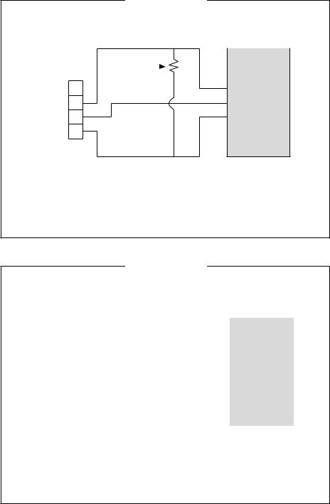
Wiring Diagram 1
OPEN COLLECTOR SIGNAL OUTPUT
|
Red |
+9 to 35 volt DC |
|
||
|
Resistor |
|
|||
Terminal |
(820 ohm min.) |
|
|
|
|
Block |
|
|
|
|
|
1 |
Black |
|
|
Common |
Customer |
|
|
|
|||
2 |
|
|
Interfacing |
||
|
|
|
(Ground) |
||
3 |
|
|
|
Equipment |
|
|
|
|
|
||
|
|
|
|
|
|
4
White
Open Collector
Signal
The terminal block is identified as follows:
Pin #1 6 volt square wave (not used)
Pin #2 +9 to 35 volt DC Input
Pin #3 Common Ground
Pin #4 Open Collector signal Output
Wiring Diagram 2
SQUARE WAVE OUTPUT
|
|
|
White |
6 volt Square |
||
|
|
|
|
Wave Signal |
|
|
Terminal |
|
|
|
|
||
Block |
|
|
|
|
|
|
1 |
|
|
|
|
Customer |
|
|
|
|
|
|
||
|
|
|
|
|
||
|
|
|
|
|
|
|
|
2 |
|
|
|
|
Interfacing |
|
|
|
|
|
|
Equipment |
|
3 |
|
|
|
|
|
|
|
|
|
|
|
|
|
4 |
|
|
|
|
|
|
|
|
Black |
Common |
|
|
|
|
|
|
|
||
|
|
|
|
(Ground) |
||
The terminal block is identified as follows: |
||||||
|
Pin #1 |
6 volt square wave |
||||
|
Pin #2 |
+9 to 35 volt DC Input (not used) |
||||
|
Pin #3 Common Ground |
|||||
|
Pin #4 |
Open Collector signal Output (not used) |
||||
2

3.Install the batteries. Make sure the positive post is in the correct position.
4.Positionthemoduleontheturbinehousing. To avoid moisture damage, make sure the seal is fully seated. Tighten the four screws on the front of the module.
Ten feet (3m) of cable is provided with the module. Trim the cable to desired length or extend it as necessary.
Verify Meter Accuracy
Before using, check the meter’s accuracy and verify calibration.
1.Make sure there is no air in the system by starting the flow until it runs steadily. Then, stop the flow using a valve or nozzle.
2.Hold down DISPLAY for 3 seconds to zero themeter’sBatchTotal.Whenzerosappear, release the button.
3.Meter an exact known volume into an accurate container. For best results, meter with one continuous full stream.
4.Check the volume against the display or recording equipment. If the amount metered is accurate, field calibration is not necessary. If not, refer to the Calibration Section for further instructions.
OPERATION
Computer Display Batch and Cumulative Totals
The display maintains two totals. The Cumulative Total provides continuous measurement and cannot be manually reset. The Batch Total can be reset to measure flow during a single use.TheCumulativeTotalis labeled withTOTAL 1 LOCKED indicating that this total is locked and cannot be manually zeroed. Batch Total is labeled with TOTAL 2.
When the Cumulative Total reaches a maximum reading of 999,999, it will automatically reset to zero.
Press the DISPLAY button briefly to switch between the batch, cumulative total, and flowrate.
NOTE: Totalization counts total units without differentiating between gallons, liters or field calibrated units.
Flowrate Feature
When this feature is activated, the word FLOWRATE displays to the left on the bottom line.
When FLOWRATE is displayed, the numbers on the middle line reflect the rate of flow, for example, the current gallons per minute (GPM) or liters per minute (LPM).
Display FLOWRATE
To use this feature, press and release DISPLAY until FLOWRATE appears to the left of the bottom line.
Activate the Meter
Turn the meter ON by starting water flow or briefly pressing the DISPLAY button. The meter will display the Batch or Cumulative Total from last use.
Press DISPLAY briefly to display the Batch Total. Hold the DISPLAY button down for 3 seconds to reset the Batch Total to zero.
The meter is programmed to turn off automatically if not used for 4 minutes.
Factory and Field Calibration Curves
All calibration information is visible to the user as words in the upper part of the display, above the numeric digits.
All units are configured with a “factory” calibration curve. Both gallons and liters are available(“GAL”or“LTR”willbedisplayed).Use the CALIBRATE and DISPLAYbuttonstoswitch between gallons and liters. This curve is NOT user adjustable: the word “PRESET” is displayedtoshowthis.(Thefactorycalibrationis stored permanently in the computer’s memory.)
The “field” calibration curve may be set by the user, and can be changed or modified at any time using the calibration procedure described below in the Calibration Section. Totals or flowrate derived from the field calibration are visiblewhenthefieldcalibrationsettingisselected (“CAL B” will be visible on the top line).
3

Selecting a Different
Calibration Setting
You can switch between GAL and LTR modes at will without “corrupting” totalizer contents. For example, the computer can totalize 10.00 gallons. If the user switches to LTR mode, the display will immediately change to “37.85” (the same amount in units of liters). GAL / LTR switching also works in FLOWRATE mode.
Toselectadifferentcalibrationsetting,firstpress and hold the CALIBRATE button. Continue to hold it while also pressing and releasing the DISPLAY button. (You may then also release the CALIBRATE button.) The flag indicators in the top line of the display will change to show the newly selected calibration setting. Calibration settings change in this order: GAL, LTR, CAL B, GAL, etc. While fluid is flowing, only the GAL and LTR selections may be made. However, when NO fluid flow is occurring, any setting may be selected.
Field Calibration
Factory calibration settings are customprogrammed into each flowmeter during production,usingwaterat70°F(21°C).Readings using the standard factory calibration curves may not be accurate in some situations
– for example, under extreme temperature conditions. You can field calibrate the meter if you are using fluids other than water.
For improved accuracy under such conditions, the OMEGA flow computer allows for “field” calibration, that is, user entry of custom calibration parameters. A “single point” calibration may yield acceptable accuracy in the middle of the flow range, but 5 or more calibration points may yield a higher level of accuracy, especially at the lower end of the flow range. Up to 15 custom calibration points can be entered.
The use of a uniformly dependable, accurate calibration container is highly recommended for the most accurate results. Due to high flowrate, it is strongly recommended that Field Calibration be completed with a combination of volume and weight using fine resolution scales.
Before Beginning Field Calibration
For the most accurate results, dispense at a flowrate which best simulates your actual operating conditions. Avoid “dribbling” more fluid or
repeatedly starting and stopping the flow – these actions will result in less accurate calibrations.
Make sure you meet the meter’s minimum flowrate requirements:
FTB690 Series Meters
1/2 inch meter |
1 |
GPM (3.8 LPM) |
|
3/4 inch meter |
2 |
GPM (7.5 LPM) |
|
1 inch meter |
5 |
GPM (18.8 LPM) |
|
1-1/2 inch meter |
10 |
GPM (37.85 LPM) |
|
2 inch meter |
20 |
GPM (75 LPM) |
|
For best results, the meter should be installed and purged of air before field calibration.
Dispense/Display Field
Calibration Procedures
1.Hold down CALIBRATE while pressing and releasing DISPLAY until the field calibration curve appears (“CAL B” message will be displayed). Release both buttons.
2.To calibrate, press and hold the CALIBRATE button. While continuing to hold CALIBRATE, also press and hold the DISPLAYbutton.Holdbothbuttonsforabout 3 seconds until you see a blinking “dd CAL” message. Once the “dd CAL” message appears, release both buttons. You are now in field calibration mode.
3.Once the buttons have been released from Step 2, the display will show the blinking message “run 01”. If you want to exit the calibration now before dispensing any fluid, go to Step 11.
4.If you want to continue with the calibration, but have not dispensed any fluid yet, make your final preparations to your pumping system, but don’t start pumping yet.
5.Start your pumping system so that fluid flows through the meter. The display will stop blinking and show the “run 01” message. Dispense into a container that allows you to judge the amount of fluid pumped. When you have pumped the desired amount (for example, 10 gallons), stop the fluid flow quickly.
6.Once the flow has stopped, briefly press and release both buttons. At this point the computer display will change to “0000.00” with the left-hand digit blinking.
4

7.Enter the volume (amount) of fluid that you dispensed (for example, if your 10-gallon container is full, enter “10.0” for gallons or “37.85” for liters). To enter numbers, use the CALIBRATE button to change the value of thedigitthatisblinkingandusetheDISPLAY button to shift the “blink” to the next digit.
8.Once the correct number is entered, briefly press and release both buttons. The displaywillnowchangetoablinking “run02” message.Youhaveinstalledthenewcal-curve point. You are ready to end calibration (Step 10) or enter another new calibration point (Step 9).
9.To enter another calibration point, go back and repeat Steps 3 through 8. It is possible to set up to 15 cal-curve points, and the “run ##” message will increment each time you repeat the calibration process (run 01, run 02, run 03, etc., up to run 15).
10.To end calibration, press and hold both buttons for about 3 seconds until you see the “CAL End” message. After you release the buttons the computer will resume normal operations with the new cal point(s) active.
11.If you HAVE NOT dispensed any fluid, you can exit calibration without changing the cal curve. If the message “run 01” is showing and you have not dispensed any fluid, hold both buttons for about 3 seconds until you see a “CAL End” message. After you release the buttons, the computer will resume normal operation and the old curve (if you entered one in the past) is still intact.
MAINTENANCE
Proper handling and care will extend the life and service of the meter.
Turbine Rotor
The meter is virtually maintenance-free. However, it is important the rotor moves freely. Keep the meter clean and free of contaminants.
Iftherotor doesnotturn freely,applya penetrating lubricant on the rotor, shaft, and bearings. Remove any debris or deposits from the rotor using a soft brush or small probe. Be careful not to damage the turbine rotor or supports.
 CAUTION
Blowingcompressedairthroughtheturbine assembly could damage the rotor.
Battery Replacement
The meter is powered by two 3-volt lithium batteries which may be replaced while the meter is installed. When batteries are removed or lose power, the batch and cumulative totals resettozerobutthefieldandfactorycalibrations are retained.
If the meter display becomes dim or blank, replace the batteries as follows:
1.Remove the four Phillips-head screws from the face of the meter and lift the faceplate from the turbine.
2.Remove the old batteries and clean any corrosion from the terminals.
3.Installnewbatteries.Makesurethepositive post is in the correct position.
4.When the batteries are replaced, the faceplate will power ON. Check the display to ensure normal functions have resumed before assembling again.
5.Reseat batteries, if necessary, and position the faceplate on the turbine housing. To avoid moisture damage, make sure the seal is fully seated. Tighten the four screws on the faceplate.
SPECIFICATIONS
Inlet and Outlet:
For NPT Models:
FTB691A-NPT/FTB691A-NPT-P 1/2" NPT
FTB692A-NPT/FTB692A-NPT-P 3/4" NPT
FTB693A-NPT/FTB693A-NPT-P 1" NPT
FTB694A-NPT/FTB694A-NPT-P 1-1/2" NPT
FTB695A-NPT/FTB695A-NPT-P 2" NPT
Design Type: Turbine
Wetted Components:
Housing: PVC
Journal Bearings: Ceramic
Shaft: Tungsten Carbide
Rotor and Supports: PVDF
Retaining Washer: Stainless Steel
5

Fitting Types: Schedule 80 NPT
Max. Working Pressure: 225 PSIG @ 73°F
U.S. Measurement
Unit of Measure: Gallon |
|
|
Flow Range: |
|
|
1/2 inch |
1 - 10 GPM |
|
3/4 inch |
2 - 20 GPM |
|
1 inch |
5 - 50 GPM |
|
1-1/2 inch |
10 - 100 |
GPM |
2 inch |
20 - 200 |
GPM |
Accuracy: ± 3.0% of reading (Accuracy can be improved with field calibration)
Operating Temperature: +32° to +140° F NOTE: Do not allow fluid to freeze inside meter.
Storage Temperature: –40° to +158° F
Weight: (IncludesComputerDisplay. Conditioned Signal Module adds .30 lbs.)
1/2 inch |
.55 lbs. |
3/4 inch |
.67 lbs. |
1 inch |
.84 lbs. |
1-1/2 inch |
1.38 lbs. |
2 inch |
1.78 lbs. |
Dimensions - inches (W x H x L):
(Includes Computer Display. Conditioned Signal Module adds 1.1 inch to height)
1/2 inch |
2.0 x 2.8 x 5.5 |
3/4 inch |
2.0 x 2.9 x 5.5 |
1 inch |
2.0 x 3.3 x 6.2 |
1-1/2 inch |
2.3 x 3.9 x 7.6 |
2 inch |
3.5 x 4.5 x 7.9 |
Metric Measurement
Unit of Measure: Liter
Flow Range: |
|
1/2 inch |
3.8 - 38 LPM |
3/4 inch |
7.6 - 76 LPM |
1 inch |
19 - 190 LPM |
1-1/2 inch |
38 - 380 LPM |
2 inch |
76 - 760 LPM |
Accuracy: ± 3.0% of reading (Accuracy can be improved with field calibration)
Operating Temperature: 0° to +60° C NOTE: Do not allow fluid to freeze inside meter.
Storage Temperature: –40° to +70° C
Weight: (IncludesComputerDisplay. Conditioned Signal Module adds .136 kg)
1/2 inch |
.249 kg |
3/4 inch |
.304 kg |
1 inch |
.381 kg |
1-1/2 inch |
.626 kg |
2 inch |
.807 kg |
Dimensions - cm (W x H x L): (Includes Computer Display. Conditioned Signal Module adds
2.8 cm to height) |
|
1/2 inch |
5.0 x 7.1 x 13.9 |
3/4 inch |
5.0 x 7.3 x 13.9 |
1 inch |
5.0 x 8.3 x 15.7 |
1-1/2 inch |
5.8 x 9.9 x 19.3 |
2 inch |
8.8 x 11.4 x 20.0 |
PARTS
The following parts and accessories are available for the FTB690 Series meters:
Part No. |
Description |
|
FLSC790-BATT |
Battery Replacement Kit |
|
FTB890 O-ring |
O-Ring |
|
FTB691A-NPT-RK |
1/2 in., NPT, PVC, Turbine |
|
|
|
Assembly Kit |
FTB692A-NPT-RK |
3/4 in., NPT, PVC Turbine |
|
|
|
Assembly Kit |
FTB693A-NPT-RK |
1 in., NPT, PVC Turbine |
|
|
|
Assembly Kit |
FTB694A-NPT-RK |
1-1/2 in., NPT, PVC, |
|
|
|
Turbine Assembly Kit |
FTB695A-NPT-RK |
2 in., NPT, PVC Turbine |
|
|
|
Assembly Kit |
Computer Kits: |
|
|
FTB691-CK |
|
1/2 in., Computer Assy Kit |
FTB692-CK |
|
3/4 in., Computer Assy Kit |
FTB693-CK |
|
1 in., Computer Assy Kit |
FTB694-CK |
|
1-1/2 in., Computer |
|
|
Assy Kit |
FTB695-CK |
|
2 in., Computer Assy Kit |
6

E S P A Ñ O L
AVISO IMPORTANTE
Utilizar los metros de los Series del FTB690 con agua y otros productos químicos que son compatiblesconlescomponentesqueseexponen al líquido (véase la sección de especificaciones). No utilizar para medir el incompatible combustible o los productos químicos. Los metros de la serie del FTB690 están disponibles con una visualización electrónica local, o un módulo de salida condicionado de la señal para proporcionar una señal numérica al equipo de interconexión del cliente. Los medidores Series FTB690 miden en galones o litros. Referirse a la sección de la calibración para mayores pantalla de ordenador detalles.
Estos medidores no son legales para las aplicaciones comerciales.
Los medidores de las Series FTB690 son muy sensibles a interferencia electrónica si funcionan a 1 o 2 pulgadas de algunos motores eléctricos o de otras fuentes del uso electrónico.
INSTALACIÓN
Instalar su medidor en línea, u horizontalmente, o verticalmente, o en el extremo de la manguera adyacente al inyector. No se recomienda la instalación a las conexiones de metal. Siga estos pasos para instalar:
1.Planee instalar la turbina con una longitud mínima de la pipa recta de esta manera:
–Contra la corriente de la turbina, permita a una longitud mínima de la pipa recta de 10 veces el diámetro interno de la turbina.
–Con la corriente de la turbina, permita una longitud mínima de la pipa recta de 5 veces el diámetro interno de la turbina.
2.Para Las Conexiones Del NPT cubrir las con exiones de pipa con la vueltas de cinta del 3 a 4 veces. Cerciorarse de que la cinta no imponga en la trayectoria del flujo.
3.Unir el metro con la flecha señalada en la dirección del flujo.
4.Para Las Conexiones Del NPT utilizar solamente sus manos para apretar las conexiones del metro. No utilizar una llave inglesa o una herramienta similar para apretar. Esto puede dañar la cubierta.
Señal de Salida Condicionada Cableado De Módulo
Este módulo de Señal de salida condicionada se puede conectar para proporcionar una salida de colector abierta o de señal de onda cuadra-da de 6-voltios.
Al instalar un flujómetro de la turbina de la serie del FTB690, el factor K correcto se debe incorporar en el dispositivo de la lectura. Usted puede encontrar el factor K impreso en el cuerpo de la turbina. Todos los factores K en flujómetros del Omega se calculan en pulsos por galón (PPG).
Señal de Salida De Colector Abierto
Para alcanzar una señal de salida de colector abierto, refierase por favor al digrama eléctrico 1. El bloque de terminales está situado en el lado trasero del módulo. El módulo viene montado de fábrica para señal de colector abierta. Por favor proporcionar (el resistor de un minimo de 820 ohmios), si no es provisto por el equipo de recepción.
Diez pies (3m) de cable se proporcionan con el módulo. Ajustar el cable a la longitud deseada o extender el cable cuanto le sea necesario. Se puede alcanzar una señal de salida de colector abierto hasta distancias de 5.000 pies (1,524m).
Salida de corrente de Onda Cuadrada
Para lograr una salida de corriente de onda cuadrada, refierase por favor al digrama eléctrico 2 y utilize un FLSC790-BATT (vendido por separado) para la fuente de energia de la bateria. El bloque de terminales y la localización de la bateria están situados en el lado trasero del modulo. Acceda al módulo de la siguiente manera:
1.Quitar los cuatro tornillos de cabeza Phillips del frente del módulo. Levantar el módulo de la turbina.
7

2.Para cambiar las conexiones del bloque de terminales, aflojar los tornillos apropiados. Volver a conectar los alambres en las posiciones apropiadas y apretar los tornillos.
3.Instalar las baterias. Cerciorarse de que el poste positivo esté en la posición correcta.
4.Colocar el módulo en la cubierta de la turbina. Para evitar daños causados por la humedad, cerciorarse de que el anillo esté asentado completamente. Apretar los cuatro tornillos en el frente del módulo.
Diez pies (3m) de cable se proporcionan con el módulo. Ajustar el cable a la longitud deseada o extender el cable cuanto le sea necesario.
Verificar La Exactitud Del Metro
Antes de usar, comprobar la exactitud del metro y verificar la calibración.
1.Cerciorarse dequenohaya aireen elsistema comenzando el flujo hasta que funciona constantemente. Entonces, detenga el flujo usando una válvula o un inyector.
2.Mantenga el botón de la EXHIBICIÓN durante 3 segundos para llevar a cero el total de medidor. Cuando aparezcan los ceros, suelte el botón.
3.Con el medidor, mida un volumen exacto en un envase exacto. Para mejores resultados, medirconunacorrientecompleteycontinua.
4.Comprobar el volumen contra la pantalla o elequipodegrabacion.Silacantidadmedida es exacta, la calibración de campo no es necesaria. Si no, refeierase a la sección de la calibración.
OPERACIÓN
Pantalla de Ordenador Hornada y Totales Acumulativos
La pantalla mantiene dos totales. El total acumulativo proporciona la medida continua y no puede ser reajustado manualmente. El total de hornada se puede reajustar para medir el flujo durante una sola vez . El total acumulativo se etiqueta con el TOTAL 1 LOCKED. Esto indica que el total esta bloqueado y no puede ser puesto a cero manualmente. El total de hornada se etiqueta con el TOTAL 2.
Cuando el total acumulativo alcanza una lectura máxima de 999.999, se reajustará automáticamente a cero.
Presionar el botón de DISPLAY brevemente para cambiar entre la hornada, el total acumulativo, y el índice de flujo.
NOTA: Totalization cuenta las unidades totales sin distinguir entre los galones, los litros o las unidades calibradas de campo.
Característica Del Índice De Flujo
Cuando se activa esta característica, aparece la palabra FLOWRATE a la izquierda hasta abajo.
Cuando se exhibe el FLOWRATE, los números en la línea media reflejan el régimen, por ejemplo, los galones actuales por minuto (GPM) o los litros por minuto (LPM).
Exhibición Del Índice De Flujo
Para utilizar esta característica, presionar y soltar el botón del DISPLAY hasta que FLOWRATE aparece a la izquierda hasta abajo.
Activar El Metro
Encienda el metro comenzando el flujo del agua o brevemente presionando el botón del DISPLAY. El medidor exhibirá la hornada o el total acumulativo a partir de la última vez que fue utilizado.
Presionar el botón del DISPLAY brevemente para exhibir el total de hornada. Oprima el botón de DISPLAY por 3 segundos para reajustar el total de hornada a cero.
El medidor se apaga automáticamente si no es usado durante 4 minutos.
Curvas De Calibración De La Fábrica y Del Campo
Toda la información de la calibración es visible al usuario como palabras en la parte superior de la exhibición, sobre los dígitos numéricos.
Todas las unidades se configuran con una curva de calibración de la “fábrica”. Los galones y los litros están disponibles. (el “GAL” o el “LTR” será visible). Utilizar los botones del CALIBRATE y del DISPLAY para cambiar entre los galones y los litros. Esta curva de calibración
8
noesajustableporelusuario.LapalabraPRESET se exhibe para demostrar esto. (La calibración de la fábrica se almacena permanentemente en la memoria de computadora.)
La curva de calibración de “campo” se puede fijar por el usuario. La calibración se puede cambiar o modificar en cualquier momento usando los procedimientos de la calibración descritos en la sección de la calibración. Los totales o el índice de flujo derivados de la calibración de campo son visibles cuando se selecciona el ajuste de la calibración de campo (la “CAL B” será visible en la línea superior).
Seleccionar Un Ajuste Diverso De La Calibración
Usted puede cambiar entre los modos del GAL y del LTR a voluntad sin afectar los totales. Por ejemplo, la computadora puede sumar 10,00 galones. Si el usuario cambia al modo del LTR, la exhibición cambiará inmediatamente a “37,85” (la misma cantidad en las unidades de los litros). La conmutación del GAL/LTR también trabaja en el modo del FLOWRATE.
Para seleccionar un ajuste diverso de la calibración, oprima y sostenga el botón de la CALIBRATE. Continuar sosteniendo el botón mientras que también presiona y suelta el botón de DISPLAY. (usted puede entonces también soltar el botón de la CALIBRATE.) Los indicadores de la bandera de la línea superior de la exhibición cambiarán para demostrar el nuevo ajuste seleccionado de la calibración. Los ajustes de la calibración se cambian en este orden: GAL, LTR, CAL B, GAL, etc. Mientras que está fluyendo el líquido, sólo las selecciones del galón y del litro pueden ser hechas. Sin embargo, cuando no está fluyendo NINGÚN líquido, cualquier selección puede ser hecha.
Calibración Del Campo
Los ajustes de la calibración de la fábrica se programan especificamente en cada flujómedidor durante su producción usando agua a 70°F (21°C). Las lecturas que utilizan las curvas de calibración estándares de la fábrica pueden no ser exactas en algunas situaciones. Por ejemplo, cuando se encuentran bajo condiciones de temperatura extremas. Usted puede campo calibrar el metro si usted está utilizando los líquidos con excepción del agua.
Para la exactitud mejorada bajo tales condiciones, la computadora OMEGA de flujo tienen en cuenta la calibración del “campo” (es decir un apunte del usuario dentro de los parámetros de calibración especiales). La calibración de “un solo punto” puede rendir una exactitud aceptable en medio de la gama del flujo. Cinco o más puntos de calibración pueden rendir un nivel más alto de exactitud, especialmente en el extremo inferior de la gama del flujo. Hasta 15 puntos de calibración especiales pueden ser incorporados.
Se recomienda altamente usar un envase confiable, y exacto para la calibración. Para obtener resultados más exactos. debido al alto índice de flujo, se recomienda fuertemente que la calibración de campo esté determinada con una combinación del volumen y del peso usando las escalas de alta resolución.
Antes De Comenzar La
Calibración De Campo
Para resultados más exactos, dispense un índice de flujo que simule lo mejor posible sus condiciones de funcionamiento reales. Evite “de gotear” más líquido o en varias ocasiones, o el comenzar y de parar el flujo. Estas acciones darán lcomo resultado calibraciones menos exactas.
Cerciorese de reunir todos los requisitos mínimos del índice de flujo del medidor:
Medidores de las Series del FTB690
Medidor de 1/2 pulgada de 1 GPM (3,8 LPM)
Medidor de 3/4 pulgada de 2 GPM (7,5 LPM)
Medidor de 1 pulgada de 5 GPM (18,8 LPM)
Medidor de 1-1/2 pulgadas de 10 GPM (37,85 LPM)
Medidor de 2 pulgadas de 20 GPM (75 LPM)
Para mejores resultados, el medidor se debe instalar y purgar del aire antes de la calibración de campo.
9
 Loading...