


OS151-HT-2

®
®
User’s Guide
Shop online at
omega.com
e-mail: info@omega.com
For latest product manuals:
omegamanual.info
MADE IN UNITED KINGDOM
®
OS210 SERIES
IR Temperature Sensors

®
OMEGAnet®Online Service Internet e-mail
omega.com info@omega.com
Servicing North America:
U.S.A.: One Omega Drive, Box 4047
ISO 9001 Certified Stamford CT 06907-0047
Tel: (203) 359-1660
FAX: (203) 359-7700
e-mail: info@omega.com
Canada: 976 Bergar
Laval (Quebec) H7L 5A1, Canada
Tel: (514) 856-6928
FAX: (514) 856-6886
e-mail: info@omega.ca
For immediate technical or application assistance:
U.S.A. and Canada: Sales Service: 1-800-826-6342/1-800-TC-OMEGA
Customer Service: 1-800-622-2378/1-800-622-BEST
Engineering Service: 1-800-872-9436/1-800-USA-WHEN
Mexico:
En Espan˜ol: (001) 203-359-7803
FAX: (001) 203-359-7807
e-mail: espanol@omega.com
info@omega.com.mx
®
®
®
Servicing Europe:
Benelux: Managed by the United Kingdom Office
Czech Republic: Frystatska 184, 733 01 Karvina´ , Czech Republic
Germany/Austria: Daimlerstrasse 26, D-75392 Deckenpfronn, Germany
United Kingdom:
ISO 9002 Certified Northbank, Irlam, Manchester
It is the policy of OMEGA Engineering, Inc.to comply with all worldwide safety and EMC/EMI
regulations that apply. OMEGA is constantly pursuing certification of its products to the European
New Approach Directives. OMEGA will add the CE mark to every appropriate device upon
certification.
The information contained in this document is believed to be correct, but OMEGA accepts no liability for any
errors it contains, and reserves the right to alter specifications without notice.
WARNING: These products are not designed for use in, and should not be used for, human applications.
Toll-Free: 0800 099 3344TEL: +31 20 347 21 21
FAX: +31 20 643 46 43 e-mail: sales@omegaeng.nl
Tel: +420 (0)59 6311899
FAX: +420 (0)59 6311114
Toll Free: 0800-1-66342
e-mail: info@omegashop.cz
Tel: +49 (0)7056 9398-0
FAX: +49 (0)7056 9398-29
Toll Free in Germany: 0800 639 7678
e-mail: info@omega.de
One Omega Drive, River Bend Technology Centre
M44 5BD United Kingdom
Tel: +44 (0)161 777 6611
FAX: +44 (0)161 777 6622
Toll Free in United Kingdom: 0800-488-488
e-mail: sales@omega.co.uk

OS210 Series non-contact infrared sensors measure temperatures from -20°C to 500°C and provide either a linear 4 to 20mA output, a voltage output or a thermocouple output. This range of
output signals is compatible with almost any indicator, controller, recorder, data logger etc., without
the need for special interfacing or signal conditioning. They are suitable for most materials such as
food, paper, textiles, plastics, leather, tobacco, pharmaceuticals, chemicals, rubber, coal and
asphalt; but not materials with a low emissivity, for example polished metals.
OS210 sensors are available as either two-wire or four-wire units.
Two-wire OS210 sensors transmit the target temperature as a 4-20 mA output and offer a simple
solution for most non-contact temperature measurement applications.
Four-wire OS210 sensors transmit the target temperature as a 0-50 mV or thermocouple output
(type J, K or T) plus the internal sensor temperature as a 4-20 mA output. This second output can
be used to ensure that the sensor is being operated within the correct ambient temperature limits
and prevent damage caused by overheating or overcooling. It can also be used to give an approx-
imate indication of the air temperature surrounding the sensor.
Specification
Temperature Range vs Field-of-View table
Field of View -20ºC to 100ºC 0ºC to 250ºC 0ºC to 500ºC
2:1 OS211-LT-X OS211-MT-X 15:1 OS151-LT-X OS151-MT-X OS151-HT-X
30:1 OS301-LT-X OS301-MT-X OS301-HT-X
ø5mm @ 100mm OS801-LT-X OS801-MT-X OS801-HT-X
Output table
Model-X Target Temperature Output Sensor Temperature Output
(blank) 4-20 mA Not available
-1 0-50 mV 4-20 mA
-2 Type T thermocouple 4-20 mA
-3 Type J thermocouple 4-20 mA
-4 Type K thermocouple 4-20 mA
english
GENERAL
Accuracy ±1% of reading or ±1°C whichever is greater
Repeatability ±0.5% of reading or ±0.5°C whichever is greater
Emissivity 0.95 (fixed)
Response Time 240ms (90% response)
Spectral Response 8 to 14µm
Supply Voltage 24Vdc (28Vdc max.)
Sensor Voltage 6Vdc min.
Maximum Loop Impedance 900 Ohms (4-20mA output)
Output Impedance 56 Ohms (voltage/thermocouple output)
MECHANICAL
Construction Stainless Steel
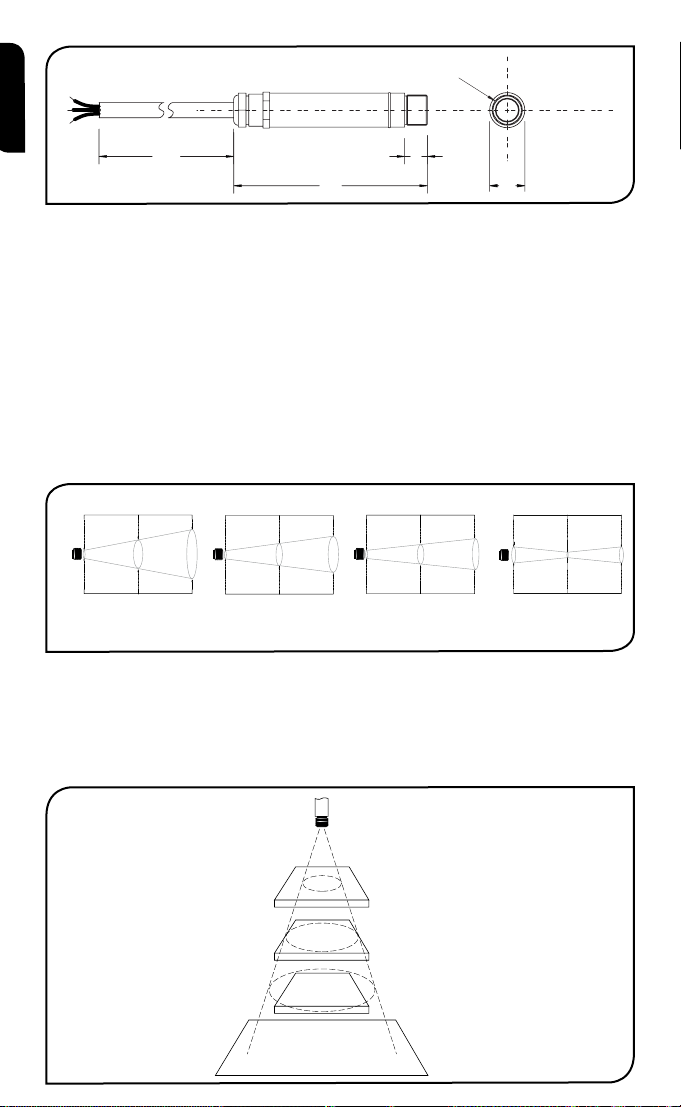
Dimensions 18mm diameter x 103mm
Cable Length 1m
Weight with Cable 95g
ENVIRONMENTAL
Environmental Rating IP65
Ambient Temperature Range 0°C to 70°C
Relative Humidity 95% maximum non-condensing
›
3
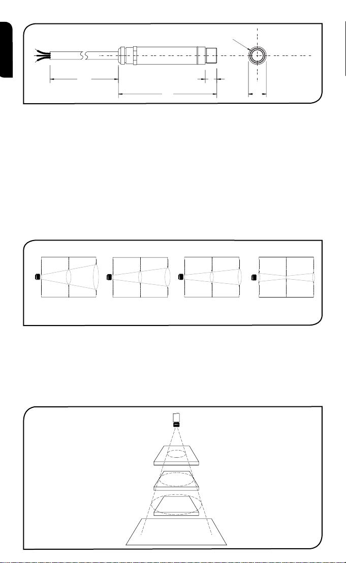
1000
103
12
18
M16 x 1mm
Distance: Sensor to object (inches)
Distance: Sensor to object (mm)
11.9
45.2
78.6
0.5
1.8
3.1
0 19.7 39.4
0
11.9
0
500 1000
Spot Dia.
(inches)
Spot Dia.
(mm)
Spot Dia.
(inches)
Spot Dia.
(mm)
Distance: Sensor to object (inches)
Distance: Sensor to object (mm)
Spot Dia.
(inches)
Spot Dia.
(mm)
Distance: Sensor to object (inches)
Distance: Sensor to object (mm)
11.9
0.5
61.9
111.9
0.5
2.4
4.4
048
0
0
5.0
0.20
100
3.9
12.5
0.49
200
7.9
100 200
D:S 15:1D:S 2:1
OS211 OS801OS151
Distance: Sensor to object (inches)
Distance: Sensor to object (mm)
11.9
28.6
45.2
0.5
1.1
1.8
0 19.7 39.4
0 500 1000
Spot Dia.
(inches)
Spot Dia.
(mm)
D:S 30:1
OS301
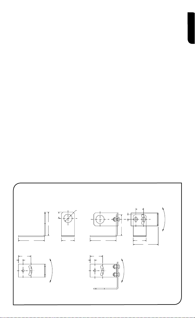
Sensor
BEST
GOOD
INCORREC
Background
Target greater
than spot size
Target equal to
spot size
Target smaller
than spot size
english
acceSSorieS
A range of accessories to suit different applications and industrial environments is available. These
may be ordered at any time and added on-site. The accessories consist of the following parts .
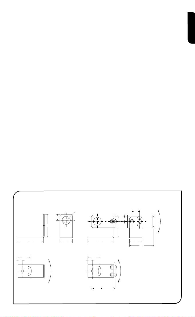
Fixed mounting bracket Adjustable mounting bracket Air purge collar
Laser sighting tool
optionS
The following options are available. Options are factory installed and must be ordered with the
OS210.
Air/water cooled housing Certificate of calibration Longer cable (30m max.)
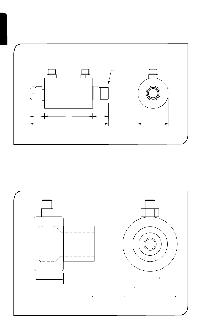
optical cHart
The optical chart below indicates the nominal target spot diameter at any given distance from the
sensing head and assumes 90% energy.
inStallation
The installation process consists of the following stages:
Preparation Mechanical installation Electrical installation
Please read the following sections thoroughly before proceeding with the installation.
preparation
Ensure that the sensor is positioned so that it is focused on the target only.
4
›
T
DISTANCE AND SPOT SIZE
12.0
45.0
50.0 50.0
40.0
9.0
15.0
25.0 25.0
60° Rotation 60° Rotation
60° Rotation
9.0
48.0
Fixed Bracket Adjustable Bracket
2 x Mounting Holes M4 Clearance 2 x Mounting Holes M4 Clearance
9.0
24.024.0
Ø16.0
The size of the area (spot size) to be measured determines the distance between the sensor and
the target. The spot size must not be larger than the target. The sensor should be mounted so
that the measured spot size is smaller than the target.
AMBIENT TEMPERATURE
The sensor is designed to operate in ambient temperatures from 0°C to 70°C. For ambient temperatures above 70°C, an air/water-cooled housing will be required.
Avoid thermal shock. Allow 20 minutes for the unit to adjust to large changes in ambient temperature.
ATMOSPHERIC QUALITY
Smoke, fumes or dust can contaminate the lens and cause errors in temperature measurement.
In these types of environment the air purge collar should be used to help keep the lens clean.
ELECTRICAL INTERFERENCE
To minimise electromagnetic interference or ‘noise’, the sensor should be mounted away from
motors, generators and such like.
WIRING
Check the distance between the sensor and the indicating/controlling device. If necessary, the
OS210 sensor can be ordered with a longer cable attached.
POWER SUPPLY
Be sure to use a 24Vdc, (25mA) power supply.
mecHanical inStallation
All sensors come with a 1m cable and a mounting nut. The sensor can be mounted on brackets
or cut outs of your own design, or you can use the fixed and adjustable mounting bracket accessories which are shown below. Note: The OS210 sensor housing must be connected to earth at
one point, either the cable shield termination or the sensor housing.
english
›
5
AIR/WATER COOLED HOUSING
40.0
2119 63
103
M16 x 1mm
1/8 BSP water/air connections
1/8 BSP Air connection
25
OS210-APSW
(for OS211)
50
OS210-APSN
(for OS151, OS301, OS801)
20
29
40
The air/water cooled housing shown below allows the sensor to withstand high ambient temperatures.
It is equipped with two 1/8” BSP fittings. Water temperature should be 10°C to 27°C for efficient cool-
english
ing. Chilled water below 10°C is not recommended. To avoid condensation, the air purge collar should
be used with the water-cooled housing. Water flow rate should not be more than 0.5 to 1.5 litres/min.
AIR PURGE COLLAR
The air purge collar below is used to keep dust, fumes, moisture, and other contaminants away
from the lens. It must be screwed in fully. Air flows into the 1/8” BSP fitting and out of the front
aperture. Air flow should be no more than 5 to 15 litres/min.
Clean or ‘instrument’ air is recommended.
6
›
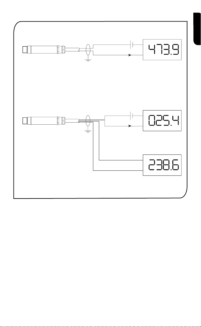
electrical inStallation
+-
-
+
Display/Controller
4-20mA = Target
4-20mA
Temperature
Power Supply
+-
-
+
4-20mA = Sensor
Temperature
Power Supply
-
+
mV/TC = Target
Temperature
Two-wire units
Four-wire units (options 1 to 4)
OP-
OP+
PWR+
PWR-
PWR+
PWR-
Display/Controller
Display/Controller
4-20mA
english
operation
Once the sensor is in position and the appropriate power, air, water, and cable connections are secure,
the system is ready for continuous operation by completing the following simple steps:
1. Turn on the power supply
2. Turn on the meter, chart recorder or controller
3. Read / monitor the temperature
IMPORTANT
Be aware of the following when using the sensor:
• If the sensor is exposed to significant changes in ambient temperature (hot to cold, or cold to hot),
allow 20 minutes for the temperature to stabilise before taking or recording measurements.
• Do not operate the sensor near large electromagnetic fields (e.g. around arc welders or induction
heaters).
Electromagnetic interference can cause measurement errors.
• Wire must be connected only to the appropriate terminals.
›
7

MAINTENANCE
Our customer service representatives are available for application assistance, calibration, repair, and
english
solutions to specific problems. Contact our Service Department before returning any equipment. In
many cases, problems can be solved over the telephone. If the sensor is not performing as it should,
try to match the symptom below to the problem. If the table does not help, call Omega for further
advice.
Troubleshooting
Symptom Probable Cause Solution
No output No power to sensor Check power supply
Erroneous temperature Incorrect wire connection Check wire colour codes
Erroneous temperature Faulty sensor cable Verify cable continuity
Erroneous temperature Field of view obstruction Remove obstruction
LENS CLEANING
Keep the lens clean at all times. Any foreign matter on the lens would affect measurement accuracy.
Blow off loose particles (if not using the air purge accessory) with an air ‘puffer’.
8
›

Les Pyromètres infra rouges de la série de OS210 mesurent des températures de -20ºC à 500ºC
et possèdent une Sortie linéaire 4..20mA, une Sortie tension ou une Sortie thermocouple. Cette
gamme des signaux de sortie est compatible avec la plus part des indicateurs, contrôleurs, enregistreur, centrale d’acquisition de données etc., sans avoir besoin d’interfaces ou de conditionnements de signal particuliers. Ils conviennent à la plupart des matériaux tels que la nourriture, le
papier, les textiles, les plastiques, le cuir, le tabac, les produits pharmaceutiques, les produits
chimiques, le caoutchouc, le charbon et l’asphalte, exceptés les matériaux à faible émissivité, par
exemple les métaux polis.
Les détecteurs OS210 sont disponibles en unités à deux ou à quatre fils.
Les détecteurs OS210 à deux fils transmettent la température cible sous forme d’une sortie à 4-20
mA et représentent une solution simple pour la plupart des applications de mesure de température
sans contact.
Les détecteurs OS210 à quatre fils transmettent la température cible sous forme d’une sortie à
0-50 mV ou thermocouple (type J, K ou T), ainsi que la température interne du détecteur sous
forme d’une sortie à 4-20 mA. On peut utiliser cette deuxième sortie afin de s’assurer que le détecteur fonctionne en-deçà des limitations de température ambiante, et ainsi éviter les dégâts potentiels causés par la surchauffe ou le refroidissement excessif. On peut l’utiliser également pour
obtenir une indication approximative de la température autour du détecteur.
SpécificationS
Tableau montrant la gamme de températures vs le champ de vision
Champ de Visée -20ºC à 100ºC 0ºC à 250ºC 0ºC à 500ºC
2:1 OS211-LT-X OS211-MT-X 15:1 OS151-LT-X OS151-MT-X OS151-HT-X
30:1 OS301-LT-X OS301-MT-X OS301-HT-X
ø5mm @ 100mm OS801-LT-X OS801-MT-X OS801-HT-X
Tableau des sorties
Model-X Température de sortie ciblée Température de détecteur ciblée
(vide) 4-20 mA –
-1 0-50 mV 4-20 mA
-2 T Thermocouple 4-20 mA
-3 J Thermocouple 4-20 mA
-4 K Thermocouple 4-20 mA
français
GÉNÉRALES
Précision ± 1% de la mesure ou ± 1°C, celui qui est le plus important
Fidélité ± 0,5% de la mesure ou ± 0,5°C, celui qui est le plus important
Emissivité 0,95 (fixée)
Temps de réponse 240ms (réponse 90%)
Réponse spectrale 8 à 14µm
Voltage d’alimentation 24V cc (max. 28V cc)
Voltage du détecteur Min. 6V cc
Impédance en boucle maximale 900 Ohms (4-20mA sortie)
Impédance de Sortie 56 Ohms (Tension ou rendement de thermocouple)
MÉCANIQUES
Construction Acier inoxydable
Dimensions 18mm diamètre x 103mm
Longueur du câble 1m
Poids avec câble 95g
ENVIRONNEMENTALES
Catégorie environnementale IP65
Echelle de température ambiante 0°C à 70°C
Humidité relative Maximum 95% non condensée
›
9
Détecteur
LE MEILLEUR
BON
PAS BON
Fond
Cible plus grand
que la grandeur
du point
Cible même
grandeur que
le point
Cible plus petit
que la grandeur
du point
1000
103
12
18
M16 x 1mm
Distance : Détecteur / objet (inches)
Distance : Détecteur / objet (mm)
11.9
45.2
78.6
0.5
1.8
3.1
0 19.7 39.4
0
11.9
0
500 1000
Diamètre
du point
(inches)
Diamètre
du point .
(mm)
Diamètre
du point
(inches)
Diamètre
du point .
(mm)
Distance : Détecteur / objet (inches)
Distance : Détecteur / objet (mm)
Diamètre
du point
(inches)
Diamètre
du point .
(mm)
Distance : Détecteur / objet (inches)
Distance : Détecteur / objet (mm)
11.9
0.5
61.9
111.9
0.5
2.4
4.4
048
0
0
5.0
0.20
100
3.9
12.5
0.49
200
7.9
100 200
D:S 15:1D:S 2:1
Distance : Détecteur / objet (inches)
Distance : Détecteur / objet (mm)
11.9
28.6
45.2
0.5
1.1
1.8
0 19.7 39.4
0 500 1000
Diamètre
du point
(inches)
Diamètre
du point .
(mm)
D:S 30:1
OS211 OS801OS151 OS301
français
acceSSoireS
Une gamme d’accessoires pour convenir aux différentes applications et environnements industriels
est disponible. Les accessoires peuvent être commandés à tout moment et ajoutés sur place. Ils
consistent en :
Un support de fixation fixe Un support de fixation réglable Un collier de purge d’air
Outil de visée Laser
optionS
Les options suivantes sont disponibles : Les options sont installées en usine et doivent être commandées avec le détecteur OS210.
Boîtier refroidi à l’air/eau Certificat de calibrage Câble plus long (30m max.)
taBleaU optiQUe
Le tableau optique ci-dessous indique le diamètre du point cible nominal à n’importe quelle distance de la tête de détection et assume 90% d’énergie.
inStallation
Le processus d’installation consiste aux étapes suivantes :
Préparation Installation mécanique Installation électrique
Il faut lire les sections suivantes attentivement avant de commencer l’installation.
préparation
S’assurer que le détecteur est mis en place pour qu’il ne se concentre que sur la cible.
10
›
DISTANCE ET TAILLE DU POINT
12.0
45.0
50.0 50.0
40.0
9.0
15.0
25.0 25.0
9.0
48.0
9.0
24.024.0
Ø16.0
Rotation 60° Rotation 60°
Rotation 60°
Support fixe Support réglable
2 x trous de montage, jeu M4 2 x trous de montage, jeu M4
La taille de la zone (taille du point) qui doit être mesurée détermine la distance entre le détecteur et
la cible. La taille du point ne doit pas être plus grande que la cible. Le détecteur devrait être monté
de façon à ce que la taille du point mesuré est plus petite que la cible.
TEMPÉRATURE AMBIANTE
Le détecteur est conçu pour fonctionner en températures ambiantes de 0°C à 70°C. Pour les
températures ambiantes supérieures à 70°C, un boîtier refroidi à l’air/eau est nécessaire.
Eviter les chocs thermiques. Allouer 20 minutes au thermomètre, pour qu’il s’adapte à
d’importantes fluctuations de température ambiante.
QUALITÉ ATMOSPHÉRIQUE
La fumée, les vapeurs ou la poussière peuvent contaminer la lentille et provoquer des erreurs dans
la mesure de température. Dans ces genres d’environnement, le collier de purge d’air devrait être
utilisé pour aider à garder la lentille propre.
INTERFÉRENCE ÉLECTRIQUE
Pour réduire l’interférence électromagnétique ou ‘bruit’, le détecteur devrait être monté à l’écart de
moteurs, générateurs, et autres appareils similaires.
CÂBLAGE
Vérifier la distance entre le détecteur et l’appareil d’indication / de contrôle. Si nécessaire, le
détecteur OS210 peut être commandé avec un câble attaché plus long.
ALIMENTATION ÉLECTRIQUE
S’assurer qu’une alimentation électrique de 24Vcc (25mA) est utilisée.
inStallation mécaniQUe
Tous les détecteurs sont fournis avec un câble d’un mètre et un boulon de fixation. Le détecteur
peut être monté sur un support ou sur des découpes de votre propre conception ou bien les
accessoires de support fixe et réglable, qui sont montrés ci-dessous, peuvent être utilisés. Nota: Il
faut que le détecteur soit connecté à la terre à un seul point, soit au blindage du câble, soit au
boîtier du détecteur.
français
11
›
 Loading...