


DP4 CONTROL SERIES

CONTROLS
Instruction Manual
DIGITAL SPEED POTENTIOMETER WITH DISPLAY
FOR AC AND DC DRIVES
P.O. Box 10 |
Phone (317) |
873-5211 |
5000 W. 106th Street |
Fax (317) |
873-1105 |
Zionsville, Indiana 46077 |
www.dartcontrols.com |
|
LT24 (0807) |
A-5-3128F |

Quick Jump
What models and options are available?
See page 3.
Looking for detailed specifications?
See page 3.
Want to get started fast?
See basic electrical hook-up details on page 5. See mechanical installation details on page 4.
See some sample applications starting on page 17.
Need Help?
See troubleshooting on page 22.
Warranty
Dart Controls, Inc. (DCI) warrants its products to be free from defects in material and workmanship. The exclusive remedy for this warranty is DCI factory replacement of any part or parts of such product which shall within 12 months after delivery to the purchaser be returned to DCI factory with all transportation charges prepaid and which DCI determines to its satisfaction to be defective. This warranty shall not extend to defects in assembly by other than DCI or to any article which has been repaired or altered by other than DCI or to any article which DCI determines has been subjected to improper use. DCI assumes no responsibility for the design characteristics of any unit or its operation in any circuit or assembly. This warranty is in lieu of all other warranties, express or implied; all other liabilities or obligations on the part of DCI, including consequential damages, are hereby expressly excluded.
NOTE: Carefully check the control for shipping damage. Report any damage to the carrier immediately. Do not attempt to operate the drive if visible damage is evident to either the circuit or to the electronic components.
All information contained in this manual is intended to be correct, however information and data in this manual are subject to change without notice. DCI makes no warranty of any kind with regard to this information or data. Further, DCI is not responsible for any omissions or errors or consequential damage caused by the user of the product. DCI reserves the right to make manufacturing changes which may not be included in this manual.
WARNING
Improper installation or operation of this control may cause injury to personnel or control failure. The control must be installed in accordance with local, state, and national safety codes. Make certain that the power supply is disconnected before attempting to service or remove any components!!! If the power disconnect point is out of sight, lock it in disconnected position and tag to prevent unexpected application of power. Only a qualified electrician or service personnel should perform any electrical troubleshooting or maintenance. At no time should circuit continuity be checked by shorting terminals with a screwdriver or other metal device.
Table of Contents |
|
Introduction ....................................................................................................................................... |
2 |
General Features ............................................................................................................................... |
2 |
Models & Options ............................................................................................................................. |
3 |
Model Options ............................................................................................................................... |
3 |
Available Options .......................................................................................................................... |
3 |
Specifications .................................................................................................................................... |
3 |
Electrical........................................................................................................................................ |
3 |
Mechanical .................................................................................................................................... |
3 |
Environmental ............................................................................................................................... |
3 |
Cut-out and Mounting Dimensions ................................................................................................ |
4 |
Mechanical Installation ..................................................................................................................... |
4 |
Exploded Panel View ..................................................................................................................... |
4 |
Installation & Diagrams .................................................................................................................... |
5 |
P1 Terminal Block Hook-Up Diagram ............................................................................................ |
5 |
P1 Terminal Block Descriptions ..................................................................................................... |
5 |
-1 Option Wiring ............................................................................................................................. |
6 |
Basic Operating Information ........................................................................................................... |
6 |
Visual Reference ........................................................................................................................... |
6 |
How to Change a Parameter's Value (The Short Story) ................................................................ |
7 |
Operating the User Interface (The Long Story) ............................................................................. |
7 |
Detailed Configuration Instructions ................................................................................................ |
8 |
Default Configuration ..................................................................................................................... |
8 |
Resetting the Unit to Factory Defaults........................................................................................... |
8 |
JP1 (Program Enable Jumper)...................................................................................................... |
8 |
Software Parameters..................................................................................................................... |
9 |
Parameter Descriptions ............................................................................................................... |
11 |
Application Examples ..................................................................................................................... |
17 |
User Interface for Industrial Conveyor Oven with AC Drive ....................................................... |
17 |
Digital Front Panel for Regenerative Industrial Treadmill .............................................................. |
18 |
Programmable Digital Voltage Source with Enable Switch .......................................................... |
20 |
Troubleshooting .............................................................................................................................. |
22 |
Technical Support Options .......................................................................................................... |
22 |
What's Special About www.dartcontrols.com? ........................................................................... |
22 |
1
Introduction
The DP4 digital potentiometer is a compact, microprocessor-based unit capable of being either field or factory configured for a number of industry's user-interface needs. The DP4 allows the user to adjust the displayed value via the front-panel push buttons. As the displayed value is raised or lowered, the output signal from the DP4 follows proportionally according to the unit's configuration. These units supports both unipolar and bipolar output and are capable of automatically inverting, scaling, and offsetting the output as needed. Utilizing Dart's new modular bus design techniques, the DP4 series is ideal for volume OEM applications requiring specialized inputs and outputs. Contact Dart Controls' Sales Department for details. This flexibility makes the DP4 series ideal for applications such as:
Water and Waste Treatment Systems
Conveyor Oven Controllers
Synchronized Conveyor Lines
Its durable 1/8 DIN aluminum housings can be easily mounted in a panel or control cabinet. New optional pluggable terminal block allows the installer to quickly install or replace units without the hassle of physically removing and reattaching wires. The units can be ordered with either standard Europeanstyle terminal block or optional “pluggable” connector.
General Features
-Microprocessor-based design combines the ultimate in responsiveness and accuracy in one package
-Digital front-end ensures long-term accuracy of output signal over time and temperature
-Non-volatile memory stores adjustable parameters even when power has been removed
-Factory or field programmable via front-panel keypad
-Adjustable parameters include display range, output range, output polarity, alarm options, etc.
-Internal program-enable jumper selectively prevents tampering with unit’s configuration
-Universal power supply accepts line voltages inputs from 85-265VAC @ 50-60Hz without switches or jumpers. The unit automatically adjusts as needed.
-Transient voltage protection prolongs unit's life in harsh industrial environments
-Self-contained power supply for external sensor, limited to 5V @ 50mA
-Programmable alarm output with Form C contacts rated to 250VAC @ 5A
-1/8 DIN durable aluminum housing for panel mounting.
-Large 4 digit, 1/2” LED display
-G.E. Lexan membrane and gasket (which are included) meet NEMA 4X standards when used with NEMA 4X enclosures
-European terminal block or pluggable terminal block available
-Wide operating ambient temperature range of -10C to 45C (14F to 113F)
-Multiple operating modes including:
•Rate Mode – Displays in rate and non-rate units such as RPM, Gallons per Second, & percent
•Time Mode – Displays in time units such as HH:MM, MM:SS, SS:TT, or other unit
2
Models & Options
Model Options
|
|
|
|
|
Input Voltage |
|
Pickup or |
Model |
@ 50 - 60Hz |
Output Voltage |
Encoder |
|
|
Required? |
|
|
|
|
|
|
|
|
|
DP4 |
85-265VAC |
0-2 VDC |
No |
|
|
THROUGH |
|
|
|
0-24 VDC |
|
Available Options
Option Suffix |
Description |
Example |
-1 |
Expansion board which adds support for remote push button wiring via a European-style |
DP4-1 |
|
terminal block. |
|
-P |
Optional pluggable European-style terminal block |
DP4-P |
-9 |
Blank Lexan |
DP4-9 |
Specifications |
|
|
Electrical |
|
|
|
|
|
Line Input Voltage ............................................................................................................................................... |
Any Voltage from 85-265 VAC |
|
Line Input Frequency............................................................................................................................................. |
Any Freq.from 48-62 Hertz |
|
Display Range .............................................................................................................................................................................. |
0.001 – 9999 |
|
Units of Operation.............................................................................................................................................. |
User Programmable, any Unit |
|
Onboard Power Supply (Externally Accessible) ............................................................................................................................ |
5V @ 50mA |
|
Isolated Alarm Relay Output Ratings.......................................................................................................................................... |
250VAC @ 5A |
|
Pot Lo/Hi supply VDC range.................................................................................................................................. |
0-2 VDC through 0-24 VDC |
|
Pot wiper VDC range ............................................................................................................................... |
Pot Lo +50mV through Pot Hi -50mV |
|
|
|
|
Mechanical |
|
|
|
|
|
Display Type LED, Red, 4 Digit, ½” Height |
|
|
Housing Type (with supplied gasket in NEMA 4X panel)...................................................................................................... |
1/8 DIN NEMA 4X |
|
Connector Style (pluggable connector optional)........................................................................................... |
12-position 5mm European Style |
|
Terminal Block Torque Setting........................................................................................................................................ |
4.4 in.lb.Max or .5Nm |
|
Faceplate Material ................................................................................................................................ |
Polycarbonate with GE Lexan Overlay |
|
Housing Material................................................................................................................................................................................ |
Aluminum |
|
Length (Required Panel Depth)........................................................................................................................................... |
4.625”, 117.48mm |
|
Faceplate Width .................................................................................................................................................................. |
4.539”, 115.29mm |
|
Weight ASP10 ......................................................................................................................................................... |
0.900 lb, 14.4 oz, 408.22g |
|
|
|
|
Environmental |
|
|
|
|
|
Operating Temperature Range................................................................................................................................ |
-10C to 45C (14F to 113F) |
|
Operating Humidity Range ............................................................................................................................................ |
95%, non-condensing |
|
|
|
|
3
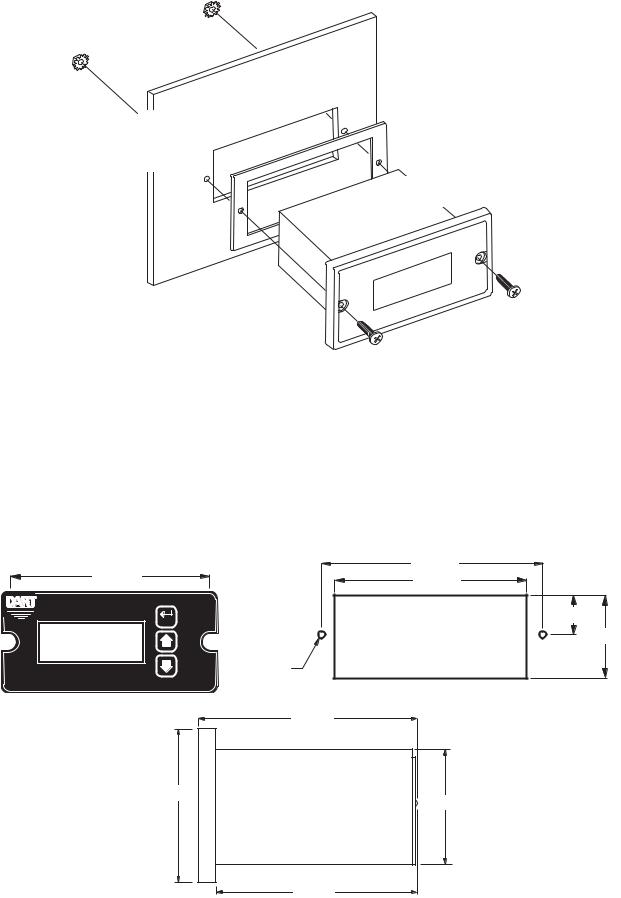
Mechanical Installation
Exploded Panel View
CUSTOMER
MOUNTING PANEL
(HOLE CUT-OUT FOR CONTROL HOUSING APPROXIMATELY 3.622" WIDE BY 1.770" HIGH)
PANEL MOUNTING GASKET
(WITH THE ADHESIVE SIDE OF GASKET FACING THE CUSTOMER MOUNTING PANEL)
DP4
CONTROL
SUPPLIED WITH EACH CONTROL:
1)GASKET
2)(2) 6-32 X 3/4 PANHEAD BLACK OXIDE STAINLESS SCREWS
3)(2) #6 NUT WITH LOCKWASHER
Cut-out and Mounting Dimensions
4.000" |
4.000" |
3.622" |
CONTROLS |
ENTER |
DP4 |
Neg Rev Fwd |
Alarm |
|
|
|
HOUSING DEPTH |
|
|
4.625" |
MICRO-DRIV |
.140" x 2 |
PANEL CUT-OUT |
DIGITAL POT |
|
|
|
|
5.000" |
2.289"
1.656"
4.625"
0.885" |
1.770" |
4
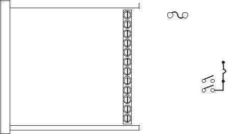
Installation & Diagrams
P1 Terminal Block Hook-Up Diagram
P1-1
P1-2
P1-3
P1-4
DP4 P1-5 P1-6
P1-7
P1-8
P1-9
P1-10
P1-11
P1-12
|
|
N |
|
|
|
|
|
|
2 AMP |
AC INPUT}85-265VAC |
||||||||||||||||||
|
|
|
|
|
|
|
|
|
|
|
|
|
|
|
|
|||||||||||||
|
|
|
|
|
|
|
|
|
|
|
|
|
|
|
|
|
||||||||||||
|
|
L |
|
|
|
|
|
|
|
|
|
|
|
|
|
|
||||||||||||
|
|
|
|
|
|
|
|
|
|
|
|
|
|
|
|
|
AC INPUT |
|
|
|||||||||
|
|
HI |
|
|
|
|
|
|
|
|
|
|
|
|
|
|
|
|
||||||||||
|
|
|
|
|
|
|
|
|
|
|
|
|
|
|
|
|
|
|
|
|
|
|
|
|
|
|
|
|
|
|
|
|
|
|
|
|
|
HIGH OUTPUT |
|
|
|
|
|
|
|
|
Connect to the speedpot |
||||||||||
|
|
|
|
|
|
|
|
|
|
|
|
|
|
|
||||||||||||||
|
|
|
|
|
|
|
|
|
|
|
|
|
|
|
|
|
|
|
||||||||||
|
|
W |
|
|
|
|
|
|
|
|
|
|
|
|
|
|
|
|
|
|
|
|
|
|
|
|
|
of the control being driven. |
|
|
|
|
|
|
|
|
WIPER OUTPUT |
|
|
|
|
|
|
|
}High must be positive |
||||||||||||
|
|
LO |
|
|
|
|
|
|
|
|
|
|
|
|
||||||||||||||
|
|
|
|
|
|
|
|
|
|
|
|
|
|
|
|
|||||||||||||
|
|
|
|
|
|
|
|
|
|
|
|
|
|
|
|
|
|
|
|
|
|
|
|
|
|
|
|
voltage with respect to low. |
|
|
|
|
|
|
|
|
LOW OUTPUT |
|
|
|
|
|
|
|
|
|
|
|
|||||||||
|
|
COM |
|
|
|
|
|
|
|
|
|
|
|
|
|
|
|
|
|
|||||||||
|
|
|
COMMON |
|
|
|
|
|
|
|
|
|
|
|
|
|
|
|
|
|
||||||||
|
|
|
|
|
|
|
|
|
|
|
|
|
|
|
|
|
|
|
|
|
||||||||
|
|
+5V |
|
|
|
|
|
|
|
|
|
|
|
|
|
|
} |
External Supply (+5V@50mA) |
||||||||||
|
|
|
|
|
+5VDC |
|
|
|
|
|
|
|
|
|
|
|
|
|
|
|||||||||
|
|
|
|
|
|
|
|
|
|
|
|
|
|
|
|
|
|
|
|
|
|
|||||||
|
|
S1 |
|
|
|
|
|
|
|
|
|
* |
|
|
|
|
|
|
||||||||||
|
|
|
|
|
SIGNAL 1 |
|
|
|
|
|
|
|
|
|
|
|
|
|||||||||||
|
|
|
|
|
|
|
|
|
|
|
|
|
|
|
|
|
|
|
|
|
|
|||||||
|
|
|
|
|
|
|
|
|
|
|
|
|
|
|
|
|
|
|
||||||||||
|
|
S2 |
|
|
|
|
|
|
|
* |
|
|
|
|
|
|
|
|
||||||||||
|
|
|
|
SIGNAL 2 |
|
|
|
|
|
|
|
|
|
|
|
|
||||||||||||
|
|
|
|
|
|
|
|
|
|
|
|
|
} |
|
|
|
|
|
||||||||||
|
|
|
|
|
|
|
|
|
|
|
|
|
|
|
|
|||||||||||||
|
|
NO Alarm Output - Normally Open |
|
|
|
|
|
|||||||||||||||||||||
|
|
C |
Alarm Output - Common |
|
|
|
|
|
Form C |
|||||||||||||||||||
|
|
|
|
|
(ProRelaygrammable)output |
|||||||||||||||||||||||
|
|
NC |
Alarm Output - Normally Closed |
|||||||||||||||||||||||||
|
|
|
|
|
|
|
|
|
|
|
|
|
|
|
|
|
|
|
|
|
|
|
|
|
|
|
|
|
|
|
|
|
|
|
|
|
|
|
|
|
|
|
|
|
|
|
|
|
|
|
|
|
|
|
|
|
|
* P1-8 & P1-9 signal inputs may be programmed for a number of functions.
P1 Terminal Block Descriptions
P1-1 (AC / N) – For single phase AC lines connect the Neutral side of your AC line to this terminal. For systems with two hot AC lines, connect either of the Hot AC lines to this terminal.
P1-2 (AC / L) – For single phase AC lines connect the Hot side of your AC line to this terminal. For systems with two hot AC lines, connect either of the Hot AC lines to this terminal.
P1-3 (HI) - This is the POT HI reference terminal. This terminal must be connected to the most positive speed pot input terminal of the partner control. This terminal will generally be referred to as Pot HI or +V for positive supplies and Com for negative supplies.
P1-4 (WP) - This is the Wiper output terminal. This terminal will output an analog voltage signal proportional to the referenced voltage signals connected to P1-3 (HI) and P1-5 (LO). This terminal should be connected to the wiper or signal input of the partner control.
P1-5 (LO) - This is the POT LO reference terminal. This terminal must be connected to the most negative speed pot input terminal of the partner control. This terminal will generally be referred to as Pot LO or Com for positive supplies and –V for negative supplies.
P1-6 (COM) – This is the common point for the control logic. Any other equipment or source needing to reference the control common will be connected to this terminal.
P1-7 (+5V) – This is a self-contained +5VDC power supply capable of up to 50mA. Various lowvoltage sensors can be driven from this supply if desired.
P1-8 (S1) – This is the programmable signal 1 input. It can be configured to perform a number of special features including inhibit and jog.
P1-9 (S2) – This is the programmable signal 2 input. It can be configured to perform a number of special features including inhibit and jog.
P1-10 (1NO) – This is the normally-open contact of the user assignable relay output. P1-11 (1C) – This is the common contact of the user assignable relay.
P1-12 (1NC) – This is the normally-closed contact of the user assignable relay output.
5

-1 Option Wiring
The -1 option board is a module which allows external up and down push buttons to be wired to the unit. These buttons operate exactly like the Up and Down buttons on the user interface. This module is commonly used to allow PLCs or hand-held pendants to operate the front-panel remotely. Wires for the external buttons are attached via a 3mm European terminal block on the -1 option board. The buttons are activated by shorting the terminal labeled Com to either the Up or Down terminal.
|
|
|
|
|
|
REMOTE SWITCHING |
||||||
|
|
DOWN UP |
||||||||||
MICROPROCESSOR |
||||||||||||
SERIES PC BOARD |
|
|
|
|
|
|
|
|||||
|
|
|
|
|
|
|
|
|
|
|
|
|
|
|
|
|
|
|
|
|
|
|
|
|
|
|
|
|
|
|
|
|
|
|
|
|
|
|
-1 OPTION
BOARD
-3 -2 -1
COMMON UP DOWN
Basic Operating Information
The DP4 digital potentiometer is a panel-mount digital-to-analog user interface. Put simply, it allows the user to adjust the displayed value via push buttons on the front panel; and, outputs a proportional signal according to its configuration. It can be configured to work with both single and bidirectional partner drives. It also supports both unipolar and bipolar output supplies.
The DP4 can display values in rate and time formats. In Rate mode, output units such as Gallons-per- Minutes, RPM, and Percent are possible with just a few minor adjustments. In Time mode, output units such as Hours:Minutes (HH:MM), Minutes:Seconds (MM:SS), and Seconds:Ticks (SS:TT) are supported. In Time modes, the output will be inversely proportional to the displayed value in order to represent a programmable process time.
See the application examples in this manual for additional information on how the DP4 can be configured.
Visual Reference
Reverse Indicator
Negative Indicator |
Forward Indicator |
|
|
Alarm Indicator |
ENTER (Select) Button |
||
|
|||
CONTROLS |
Rev Fwd Alarm |
|
|
Neg |
|
||
|
ENTER |
|
MICRODIGITAL-DRIVPOT
Up & Down Buttons
Display Window
6
How to Change a Parameter's Value (The Short Story)
1.Hold down the Enter button until Parameter-Selection Mode is entered
2.Using the Up and Down buttons, select the desired parameter number to view or edit
3.Press the Enter button to change the value of the parameter
4.Using the Up and Down buttons, change the parameter's value as desired
5.Press the Enter button to permanently save the changes (Return to Parameter-Selection Mode)
6.Select parameter zero and press the Enter button to return to Running Mode
Operating the User Interface (The Long Story)
Although the DP4 user interface is very versatile, it is also simple to setup and operate. With just a few button presses, it allows the user to configure a number of adjustable parameters. The LED display has three basic operating modes: Running Mode, Parameter-Selection Mode, and Value Mode. Each of the three modes have specific visual indicators that allow the user to immediately determine the current state or mode of the user interface. Parameter-Selection Mode and Value Mode can only be entered if the Program Enable jumper is in the “On” position.
Running Mode is the default display of the unit when power is applied. The DP4 will spend the majority of its time in this mode. In Running Mode, the display shows the target value in the appropriate userdefined format of rate, time, or percentage. The control will continuously attempt to drive the motor at the requested target rate. In this display mode, the Up and Down buttons increase or decrease the displayed target value until either the display minimum or display maximum limit is reached. Depending on the alarm configuration, these buttons may also serve as an alarm-silence or alarm-reset button. Example displays for rate, time, and follower operating modes are 13.60, 45:30, and 9301.
Parameter-Selection Mode can be entered by simply pressing and holding the Enter button down for three seconds. Once in Parameter-Selection Mode, the far left of the display will be a ‘P’. The right side of the display will indicate the currently selected parameter number for editing purposes. Pressing the Up or Down button will increase or decrease the selected parameter number on the display. Although the parameter numbers are in numerical order, some numbers are skipped. These numbers represent reserved parameters that are not yet implemented and are not displayed. Once the desired parameter number is displayed, a press of the Enter button will change the display to the Value Mode. When in
Parameter-Selection Mode, pressing the Enter button with parameter 0 selected will cause the unit to return to Running Mode. Example displays for Parameter-Selection Mode are P 1, P 12, and P 54. See the Software Parameters for a list of available parameters.
Value Mode is used to modify the value of the selected parameter. When in Value Mode, the two dots which form the colon, between digits two and three, will alternately flash (one, then the other) to inform the user that a parameter’s value is being edited. Pressing the Up or Down button increases or decreases the selected parameter’s value. See the Software Parameters for a list of allowable values and ranges. Value changes take effect immediately. For example, when scrolling through the alarm output conditions, the relay will activate as the always-active selection is passed. Once the desired value is showing in the display window, pressing the Enter button again will return to ParameterSelection Mode. The new value is not saved in permanent memory until the Enter button is pressed. Removing power from the unit while in Value Mode may result in the specified new value being lost.
7
 Loading...