


 Loading...
OMB-LogBook User’s Manual
Stand-Alone, Intelligent Systems for 16-bit Data Acquisition and Logging
p/n OMB-461-0901 Rev. 2.0

|
|
|
|
|
|
|
|
|
|
|
|
OMEGAnetSM On-Line Service |
Internet e-mail |
||||||||||
|
|
|
|
|
|
|
|
|
|
|
|
|
|
http://www.omega.com |
info@omega.com |
||||||||
|
|
|
|
|
|
|
|
|
|
|
|
|
|
|
|
|
|
|
|
|
|
|
|
|
|
|
|
|
|
|
|
|
|
|
|
|
|
|
|
|
|
|
|
|
|
6HUYLFLQJ 1RUWK $PHULFD |
|
USA: |
|
|
|
|
|
|
|
|
One Omega Drive, Box 4047 |
|
|||||||||||||
|
|
|
|
|
|
|
|
|
|
|
|
|
|
|
|
|
|
|
|
|
|
Stamford, CT 06907-0047 |
|
|
|
|
|
|
|
|
|
|
|
|
|
|
|
|
|
|
|
|
|
|
|
Tel: (203) 359-1660 |
FAX: (203) 359-7700 |
|
|
|
|
|
|
|
|
|
|
|
|
|
|
|
|
|
|
|
|
|
|
e-mail: info@omega.com |
|
Canada: |
|
|
|
|
|
|
|
|
976 Berger |
|
|||||||||||||
|
|
|
|
|
|
|
|
|
|
|
|
|
|
|
|
|
|
|
|
|
|
Laval (Quebec) H7L 5A1 |
|
|
|
|
|
|
|
|
|
|
|
|
|
|
|
|
|
|
|
|
|
|
|
Tel: (514) 856-6928 |
FAX: (514) 856-6886 |
|
|
|
|
|
|
|
|
|
|
|
|
|
|
|
|
|
|
|
|
|
|
e-mail: canada@omega.com |
|
)RU LPPHGLDWH WHFKQLFDO RU DSSOLFDWLRQ DVVLVWDQFH
USA and Canada:
Mexico and
Latin America:
Benelux:
Czech Republic:
France:
Germany/Austria:
United Kingdom:
Sales Service: 1-800-826-6342 / 1-800-TC-OMEGASM Customer Service: 1-800-622-2378 / 1-800-622-BESTSM Engineering Service: 1-800-872-9436 / 1-800-USA-WHENSM TELEX: 996404 EASYLINK: 62968934 CABLE: OMEGA
Tel: (95) 800-TC-OMEGASM |
FAX: (95) 203-359-7807 |
En Espanol: (95) 203-359-7803 |
e-mail: espanol@omega.com |
6HUYLFLQJ (XURSH
Postbus 8034, 1180 LA Amstelveen, The Netherlands
Tel: (31) 20 6418405 |
FAX: (31) 20 6434643 |
Toll Free in Benelux: 06 0993344 |
|
e-mail: nl@omega.com |
|
ul. Rude armady 1868 |
|
733 01 Karvina-Hranice |
|
Tel: 420 (69) 6311899 |
FAX: 420 (69) 6311114 |
e-mail:czech@omega.com |
|
9, rue Denis Papin, 78190 Trappes |
|
Tel: (33) 130-621-400 |
FAX: (33) 130-699-120 |
Toll Free in France: 0800-4-06342 |
|
e-mail: france@omega.com |
|
Daimlerstrasse 26, D-75392 Deckenpfronn, Germany
Tel: 49 (07056) 3017 |
FAX: 49 (07056) 8540 |
Toll Free in Germany: 0130 11 21 66 |
|
e-mail: germany@omega.com |
|
25 Swannington Road, |
P.O. Box 7, Omega Drive, |
Broughton Astley, Leicestershire, |
Irlam, Manchester, |
LE9 6TU, England |
M44 5EX, England |
Tel: 44 (1455) 285520 |
Tel: 44 (161) 777-6611 |
FAX: 44 (1455) 283912 |
FAX: 44 (161) 777-6622 |
Toll Free in England: 0800-488-488
e-mail: uk@omega.com
It is the policy of OMEGA to comply with all worldwide safety and EMC/EMI regulations that apply. OMEGA is constantly pursuing certification of its products to the European New Approach Directives. OMEGA will add the CE mark to every appropriate device upon certification.
The information contained in this document is believed to be correct but OMEGA Engineering, Inc. accepts no liability for any errors it contains, and reserves the right to alter specifications without notice.
WARNING: These products are not designed for use in, and should not be used for, patient-connected applications.

How To Use This Manual
This manual explains the setup and operation of the LogBook data acquisition system including LBK and DBK options.
Quick Start, LogBook/300 – Provides instructions for getting a basic LogBook/300 system connected, powered-up, and using LogView software to collect data.
Quick Start, LogBook/360 – Provides instructions for getting a basic LogBook/360 system connected, powered-up, and using LogView software to collect data.
Chapter 1 – System Considerations describes system features and an operational overview for both LogBook/300 and LogBook/360. Includes system block diagrams, information regarding hardware connections, and system testing. The chapter includes pinouts for P1, P2, and P3. Instructions on how to stack modules are included.
Chapter 2 – System Power describes power supplies and power requirements. Includes a DBK Power Requirement Worktable and material concerning the power-related DBK30A, DBK32A, DBK33, and DBK34.
Chapter 3 – LogView explains this windows-based application that is used to configure and run your LogBook acquisition system. A How To…section provides step-by-step instructions for a variety of acquisition tasks.
Chapter 4 – LBK Options discusses the RS-422/485 Communications Card, memory expansion, remote LogBook Terminal, four-channel Digital-to-Analog Output card, GPS support, Modem Support, and Upload Scheduler.
Chapter 5 – DBK Expansion Options discusses a large number of DBK options that can be used to expand your acquisition system.
Chapter 6 – Signal Management and Troubleshooting Tips explains basic concepts of data acquisition. Includes terminology, signal management, channel identification, and signal modes. A troubleshooting section provides solutions to common noise, wiring, and configuration problems.
Appendices
A – Calibrating DBK16 and DBK43A
B – Error Codes for LogView software and LogBook hardware.
C – Accelerometer Tutorial, primarily for the benefit of DBK4 users.
D – CE Compliance, describes general requirements for complying with CE standards.
E – Specifications lists physical and performance specifications for LogBooks, LBKs, and DBKs.
F – PostView explains how to use this program for post-acquisition data viewing.
G – PC-Card Compatibility identifies PC-Cards that are 100% compatible with LogBook’s acquisition rates, as well as cards that are not compatible.
&$87,21
Using this equipment in ways other than described in this manual can cause personal injury or equipment damage. Pay special attention to all cautions and warnings.
Check the README.TXT file for information that may not have been available at the time this manual went to press.
LogBook User’s Manual, 9-1-99 |
i |

Table of Contents
Quick Start, LogBook/300
Quick Start, LogBook/360
1 - System Considerations
LogBook Basics……1-1
Introduction ….. 1-1
Front and Rear Panels……1-2 Highlight of Features …… 1-3 LogBook/300 Block Diagram …… 1-4 LogBook/360 Block Diagram …… 1-5 System Software……1-6
Hardware-Related Details……1-7
PC-Card Swapping……1-7 Physical/Environmental Conditions……1-7 Power Supply……1-8 Microprocessor……1-8
Field-Installation Racks and Enclosures…1-8 P1, P2, P3 Port Connectors……1-9
System Design, Setup, & Expansion…1-13
Steps to Review …… 1-13 Expansion Configurations……1-13
LBK Options……1-13
DBK Options……1-14
Mechanical Setup Options……1-16 System Power Considerations……1-17
Operational Features……1-18
Data Acquisition, An Overview……1-18 LogBook System File……1-19 Communications……1-19
Triggering and Scan Timing……1-20 Scan Rate Limitations……1-20
Use of Outputs to Alarm and Control……1-22 Acquisition……1-22
Data Storage and Retrieval……1-22
2 - System Power
Overview……2-1
System Connections ……2-4 Installation and Configuration …… 2-4 LogView Setup …… 2-5
DBK30A Rechargeable Battery Module … 2-5 DBK32A Auxilliary Power Supply Card … 2-9 DBK33 Triple-Outlet Power Supply Card 2-10 DBK34 Vehicle UPS Module …… 2-11
3 - Using LogView
Understanding LogView……3-1
Modes of LogView Operation……3-2
LogView Features and Capabilities……3-4
Software User-Interface……3-4
File Management......3-7
How To… Procedures……3-10
Flowchart of a Simple Acquisition……3-11
Using an Attached LogBook……3-11
Using a Remote LogBook……3-13
Simple Data Logging……3-13
Setting Up DBK Cards……3-15
Using Multiple Timebases……3-16
Using Digital 2-Point Calibration……3-17
Using Digital Outputs As Alarms……3-19
Using Exception Capturing……3-20
Menu Descriptions……3-21
File Menu……3-21
View Menu……3-25
Device Menu……3-42
Tools Menu……3-45
Indicators Menu……3-48
4 - LBK Options
LBK Options, Location Reference…… 4-1
LBK/COM/422/485 …… 4-2
LBK/MEM1-U, Expanded Memory
(16 MB Upgrade) …… 4-3
LBK1, Remote LogBook Terminal……4-4
LBK2, Four Channel,
Digital-to-Analog Output ……4-8
LogBook/GPS (LogBook/360 Only)…… 4-9
LogBook/Modem…… 4-11
5 - DBK Expansion Options
Overview…… 5-2
LogView Setup……5-3
DBK1 16-Connector BNC Adapter
Module……5-4
DBK4 2-Channel Dynamic Signal Input
Card……5-5
DBK7 4-Channel Frequency-To-Voltage
Input Card……5-11
DBK8 Eight-Channel High-Voltage Input
Card……5-20
DBK9 Eight-Channel RTD Card……5-22
DBK10 3-Slot Expansion Chassis……5-25
DBK11A Screw-Terminal Option Card…5-26
DBK12 and DBK13
Analog Input Multiplexer Cards……5-28
DBK15 Universal Current/Voltage Input
Card……5-31
DBK16 2-Channel Strain-Gage Card……5-34
DBK17 Simultaneous Sample and Hold
Card……5-41
DBK18 Low-Pass Filter Card……5-43
DBK19 Thermocouple Card……5-46
DBK20 & DBK21 Digital I/O Cards……5-49
DBK23 Isolated Digital Input Chassis……5-50
DBK24 Isolated Digital Output Chassis…5-53
DBK25 8-Channel Relay Card……5-57
DBK40 BNC Analog Interface……5-58
DBK41 Ten-Slot Expansion Module……5-60
ii |
LogBook User’s Manual |

DBK42 16-Slot 5B
Signal Conditioning Module……5-63
DBK43A Eight-Channel
Strain-Gage Module……5-69
DBK44 2-Channel 5B
Signal-Conditioning Card……5-79
DBK45 4-Channel SSH
and Low-Pass Filter Card……5-83
DBK50/51 Voltage Input Modules……5-87
DBK52 Thermocouple Input Module……5-90
DBK53/54 Low/High-Gain
Analog Multiplexing Modules……5-93
6 - Signal Management & Troubleshooting
Overview……6-1
Channel Control and Expansion……6-3
Signal Acquisition……6-4
Sequencer……6-4
Scan Rate……6-5
Triggering……6-5 Counter/Timer Functions……6-5
Simultaneous Sample and Hold (SSH) ……6-6 Input Isolation……6-6
Signal Modes……6-7
References for Differential Modes……6-7 Unipolar and Bipolar Measurement……6-9 12-Bit vs 16-Bit Resolution……6-9
Signal Problems……6-10
Troubleshooting……6-12
Troubleshooting Checklist……6-12 Electrostatic Discharge (ESD) ……6-12 Radio Frequency Interference……6-12 Customer Assistance……6-13
Appendices
A – Calibrating DBK16 & DBK43A
B – Error Codes
C – Accelerometer Tutorial
D – CE Compliance
E – Specifications
F – PostView
G – PC-Card Compatibility
LogBook User’s Manual |
iii |

iv |
LogBook User’s Manual |
Quick Start, LogBook/300
Hardware Connection……1* |
Test Hardware…… 5 |
Hardware Configuration…… 3 |
Acquisition Configuration……5 |
Software Installation…… 3 |
Calibration…… 6 |
LogBook/300 Device Configuration……3 |
|
*Page numbers refer to QS-300 pages. |
|
Reference Notes: You may need to refer to additional sections of this manual.
SChapter 1, for system block diagrams, operational overviews, connections, memory upgrade procedure, or information on the RS-422/485 option.
SChapter 2, in regard to calculating system power and ensuring an adequate power supply.
SChapter 4, if using LBK options.
SChapter 5, if using DBK options.
:$51,1*
Electric shock hazard. Turn off power to all system-connected devices prior to connecting or disconnecting cables, or setting hardware configurations. Failure to do so could result in electric shock or death, and equipment damage, even under low-voltage conditions.
When using LogBook in attached mode, the PC-Card [in LogBook] must already have the file logbook.sys. Otherwise, LogView cannot communicate with LogBook, and LogBook will appear dead.
Hardware Connection
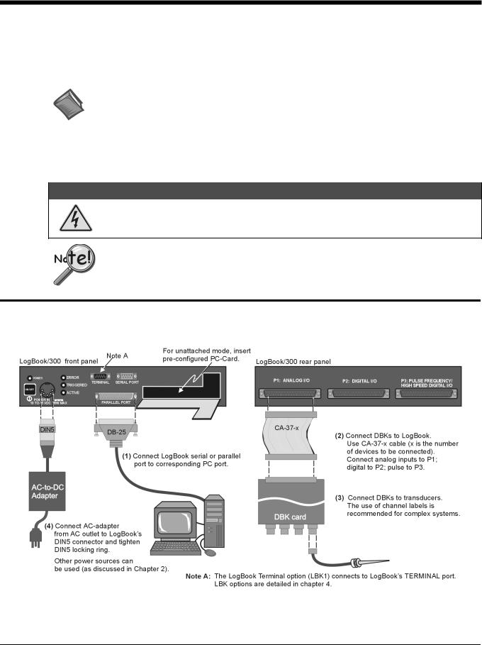
The following hardware-connection figure and procedure are generic; details vary with system complexity.
LogBook/300 System, Basic Connections
Note: There are two styles of LogBook/300. The earlier version’s PC-Card door is hinged on the right edge. The newer model, represented in the figure, is hinged on the lower edge.
LogBook User’s Manual, 8-17-99 |
Quick Start, LogBook/300 QS-300-1 |
After verifying that all equipment power is off, hardware connection typically proceeds as follows. Refer to the previous figure as needed.
1.Connect LogBook to PC. There are three ways for LogBook to communicate with the host PC. These are: parallel port, serial port, or by physical transportation of the PC-Card. Note that the parallel port method is represented in the previous figure.
a)Parallel port – If using the parallel port, connect the supplied 2-foot parallel port (DB25) cable to PARALLEL PORT on LogBook, and to the corresponding parallel port on the PC. When this method is used, the PC must be set to the ECP mode. See ECP Parallel Port, page 4 for additional information.
b)Serial port – If using the serial port, connect the supplied 6-foot serial-port (DB9) cable to SERIAL PORT on LogBook, and to the corresponding serial port on the PC.
c)PC-Card - As described chapter 1’s PC-Card Swapping section, LogBook does not require an electrical connection to the PC. The PC-Card must be pre-configured [from LogView on the PC] to contain the desired configuration file. Then the PC-Card is inserted into the corresponding slot behind the door on the LogBook’s front panel.
2.Connect the LogBook to the DBK cards and modules. Most of the analog DBKs connect to P1 on the rear panel; the digital DBKs generally connect to P2—refer to documentation for your particular DBKs in chapter 5 and for general DBK installation details. The CA-37-x cable can daisy-chain several DBKs including the DBK41, which has a built-in P1 bus connection for 10 DBK cards.
The x in the cable part number refers to the number of devices that can be connected (a CA-37-1 cable actually has two DB-37 connectors). The P1/P2 pinouts are included in chapter 1. Observe the input signal strength limitation as cautioned below—especially if using a non-DBK source.
&$87,21
For analog signal inputs via P1, do not exceed -35 VDC or +45 VDC.
Exceeding these limits could result in equipment damage.
3.Connect DBK(s) to transducer(s). Follow instructions for particular DBK as described in chapter 5 and for the particular transducer. Some DBKs can accommodate both BNC and screw-terminal connections.
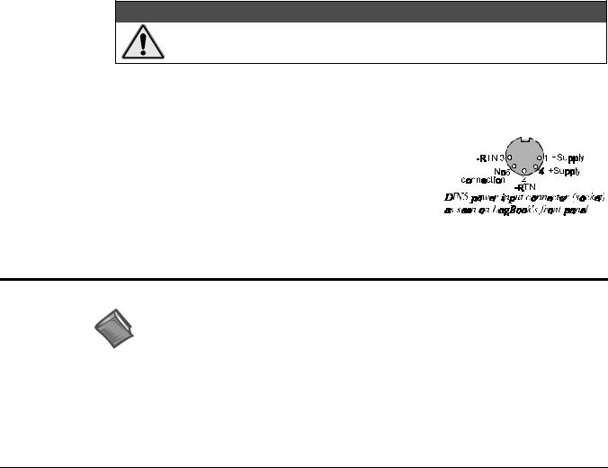
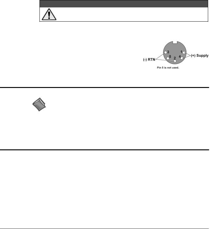
4. Connect LogBook to a suitable power source. The easiest connection is to use the TR-43 AC-to-DC power source or the DBK34. DC power sources such as a car batteries, etc must supply 10 to 45 VDC and use the correct DIN5 pinout (see figure). A locking DIN5 connector assures a secure power connection for applications subject to vibration or thermal stress.
5.(optional) Just one cable connects between the LBK1 (via RJ-11 connector) and the LogBook (via a DB9 connector). The standard cable is 6 ft long, and an optional cable is 25 ft long (see chapter 4 for LBK1 installation details).
Hardware Configuration
Reference Notes:
(1)Refer to chapter 4 in regard to the various LBK options.
(2)Some DBKs require manual configuration. Refer to chapter 5 for specific DBK
information.
LogBook's top cover does not need to be removed, except to add or remove an LBK option, or to replace the fuse.
Most LogBook configuration is done via software as described in section, LogBook/300 Device Configuration. Except when using the RS-485 communication option, LogBook configuration does not require you to set jumpers or switches.
QS-300-2 Quick Start, LogBook/300, 8-17-99 |
LogBook User’s Manual |
Software Installation
Note: The LogBook is supported under Windows95/98 and WindowsNT. Your computer should be a 486 or higher (Pentium® recommended) with at least 16 Mbytes of RAM. 32 Mbytes of RAM is recommended.
Note: Before installing software, ensure LogBook is connected to the selected port (serial, or ECP-parallel); and power-on the system.
Install installation CD-ROM (or installation disks, as applicable). Run the Setup.exe and follow screen prompts.
When the software installation is complete, you will be given two options:
•Exit running the configuration utility—if the LogBook is to be used immediately.
•Exit and return to operating system—you can run the configuration later from the control panel.
LogBook/300 Device Configuration
A configuration utility is supplied via a control panel applet. The LogBook Configuration applet allows you to add a device, remove a device, or change existing configuration settings. From this same window, you can also access a built-in utility to test the connected device for current setup and performance.
LogBook Configuration can be found in the Windows95/98/NT control panel. This can be navigated to from Window’s desktop Start button:
Start Settings Control Panel
You can enter LogBook Configuration during driver installation or whenever you wish to add, remove or change device configuration settings. The following description applies to either method.
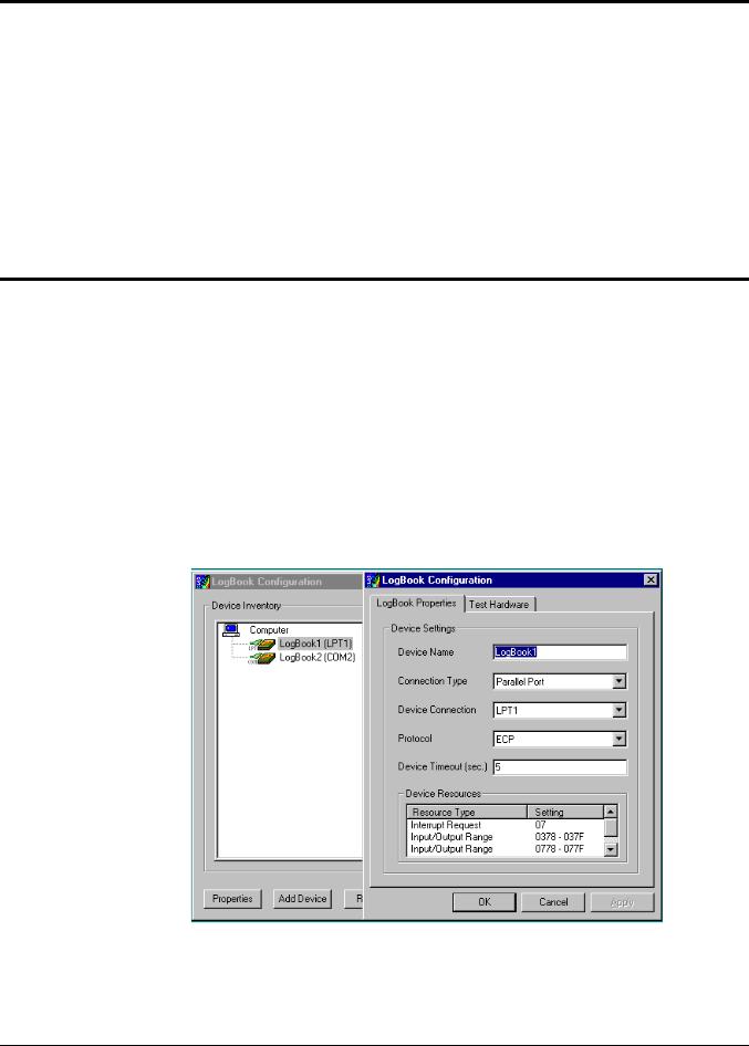
The 1st configuration window will display configured devices in the Device Inventory field based on the port they’re connected to. Devices are indicated by their name and icon. If no devices are currently configured, no devices will appear in this field. (The figure shows the 1st and 2nd configuration windows overlapping.)
LogBook Configuration Windows
LogBook User’s Manual, 8-17-99 |
Quick Start, LogBook/300 QS-300-3 |
The 4 buttons across the bottom of the 1st configuration window (previous figure) are used as follows:
•Properties. Configuration settings for a device can be changed or modified from the corresponding
properties window. To do so, double-click the device icon or single-click the device and then singleclick the Properties button. The 2nd configuration window will appear for the selected device as shown in the previous figure.
•Add. The Add Device button is used to add a device configuration whenever a new device is added to the system. LogView cannot recognize a device unless listed in the configuration window.
•Remove. The Remove button is used to remove a device from the configuration. A device may be removed if it is no longer installed or if the device’s configuration no longer applies.
•Close. The Close button may be used at any time to exit the LogBook Configuration applet.
The 2nd configuration window displays the properties for the selected LogBook. Fields include:
•Device Name is displayed with the default name, numbered successively as configured. This field can be changed to any descriptive name as desired.
•Connection Type can be serial or parallel port.
•Device Connection specifies the port name.
•Protocol is used to set the parallel port protocol (ECP only) or serial protocol (RS-232 or RS-485).
•Device Timeout specifies the number of seconds LogView will be wait for a LogBook response before displaying an error condition.
ECP Parallel Port
To use parallel port communication with an attached LogBook, your PC must support the ECP protocol AND be set in the ECP mode.
PCs made since 1994 probably support the Enhanced Computer Port protocol (ECP). If your parallel port does not support ECP, you can communicate with the LogBook via the RS-232 serial port, or you can add an ECP-compatible ISA board or PC-Card parallel port. Setting the PC to ECP mode varies with different computers. On some computers, you can enter the BIOS Setup utility from Windows Settings or during startup by pressing the F1 function key. The Parallel Port Mode property can be found under the Peripheral Configuration group menu item. If necessary, consult your PC’s documentation or your PC’s manufacturer.
To ensure ECP compatibility after proper setup, use the Test Hardware utility (described on page 5). Before testing, make sure LogBook is properly connected, powered on, and that the Parallel Port Mode is set to ECP (in BIOS Setup).
&$87,21
Making errors in BIOS Setup can disrupt your system’s operation. If test hardware indicates a problem and you have inadequate experience with the BIOS Setup utility, consult your System Administrator or other qualified individual.
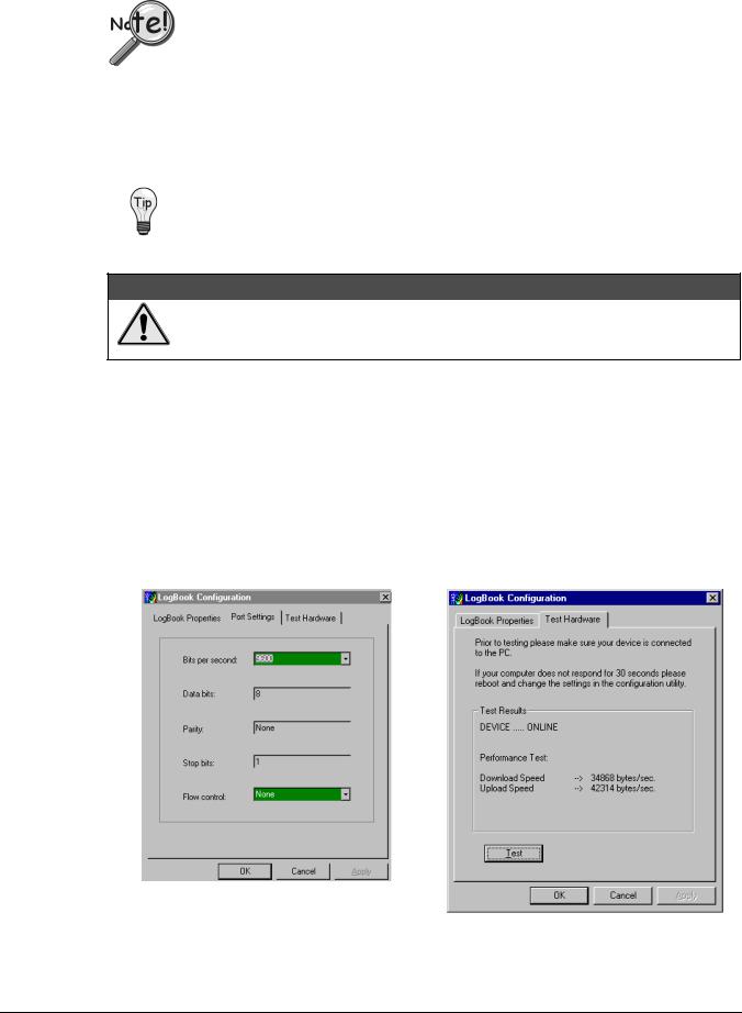
Serial Port
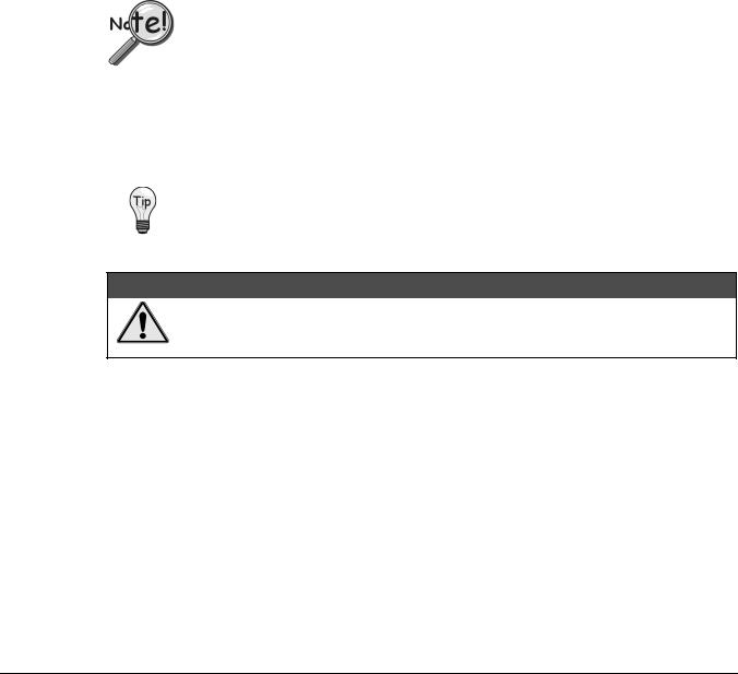
If the selected device is connected to a serial port the properties window will include the fields shown in the figure at right. Baud rate can be set from 1200 to 115200 bits per second (default 9600). When all fields have been changed to the desired settings, you can click on one of the following options:
•Apply to store the device configuration. Parameters are not locked in until you click the Apply button. If you make changes and don’t click Apply, clicking the Test button in Test Hardware will yield unexpected errors.
•OK to store the configuration and exit the current property screen.
•Cancel to exit the current screen without storing any changes.
•Test Hardware to test the current device.
QS-300-4 Quick Start, LogBook/300, 8-17-99 |
LogBook User’s Manual |
LogBook Properties Tab |
Test Hardware Tab |
Test Hardware
Before testing LogBook/300:
(a)Verify the device has been properly installed
(b)Make sure the communication cable (serial or parallel) is firmly in place to the proper ports.
(c)Verify the device is powered-on.
Testing the LogBook device might cause the system to hang. If test results are not displayed within 30 seconds, or if the system does not respond properly: reboot the system. Upon power-up, re-enter the LogBook Configuration and ensure the LogBook configuration settings are correct. Change the settings as applicable.
To begin the test, click the Test button. Test results should be displayed within a few seconds.
Test results indicate if the device is online (properly connected, powered on and ready to transfer the data) or offline. If the device is online, Performance Test will display Download and Upload speed rates. These rates represent the maximum speed at which downloading and uploading files can be performed. Actual transfer time will depend on channel configuration and the size of the transfer.
Acquisition Configuration
An acquisition is configured using LogView on a PC and then stored as an acquisition setup file on a PC-Card. The PC-Card may be in an attached LogBook or in the PC to be later manually transferred to an unattached LogBook. The system’s DBK cards are listed; the scan sequence is defined; the trigger conditions are specified, etc.
Reference Note: Configuring the acquisition is described in chapter 3, LogView.
LogBook User’s Manual, 8-17-99 |
Quick Start, LogBook/300 QS-300-5 |

Calibration
Calibration is typically performed automatically through LogView software; however, some DBKs may require manual calibration. LogView’s 2-point calibration fine-tunes the reading’s slope and offset error (mx+b). DBKs working with non-linear sensors typically condition/convert the reading to a linear form. Otherwise, a non-linear analog input signal is difficult to read accurately. Careful use of the calculated channels may yield usable approximations in simple, limited-range conditions.
Reference Note: An example of 2-point calibration is given in the How To… section of chapter 3, LogView.
Appendix A details the calibration methods applicable to DBK16 and DBK43.
QS-300-6 Quick Start, LogBook/300, 8-17-99 |
LogBook User’s Manual |
Quick Start, LogBook/360
Card Drawer Setup……2
Connect LogBook/360 to PC,
External DBKs, and Power…..5
Hardware Configuration…… 6
Software Installation…… 6
LogBook/360 Device Configuration……7
Test Hardware…… 9
Acquisition Configuration……9
Calibration…… 9
*Page numbers refer to QS-360 section.
LogBook/360, Front Panel
Reference Notes: You may need to refer to additional sections of this manual.
SChapter 1, for system block diagrams, operational overviews, connections, memory upgrade procedure, or information on the RS-422/485 option.
SChapter 2, in regard to calculating system power and ensuring an adequate power supply.
SChapter 4, if using LBK options.
SChapter 5, if using DBK options.
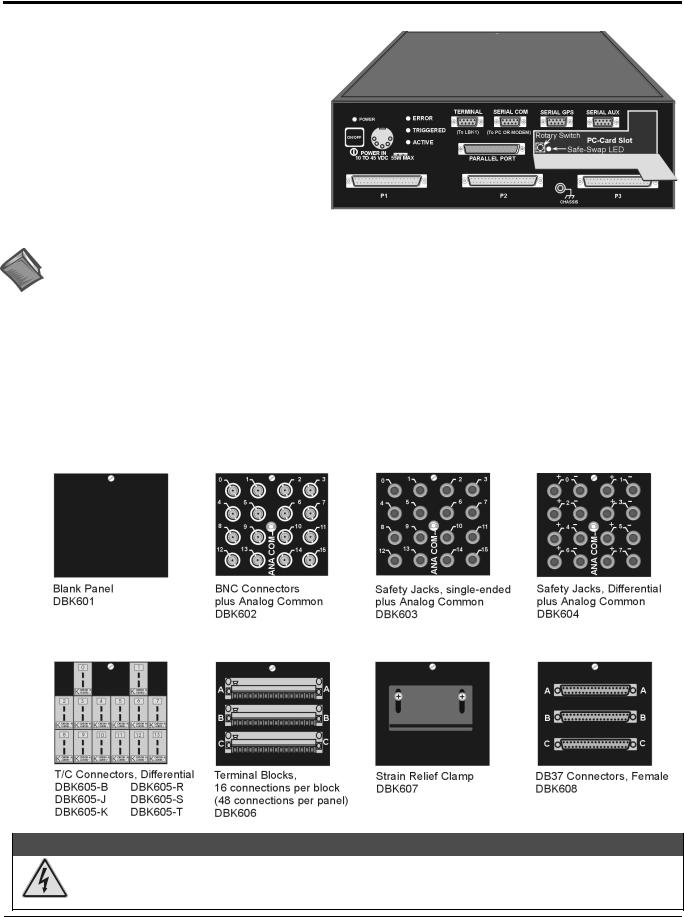
LogBook/360 combines the features and capabilities of LogBook/300 with a DBK60 expansion chassis. The lower portion of the front panel has three male DB37 connectors (P1, P2, and P3) for system expansion, and a post for connecting to CHASSIS ground.
The upper section is nearly identical to LogBook/300, and is detailed in chapter 1.
The rear panel consists of three termination panels. Many different combinations of three panels are possible. Termination panels available at the time of publication are represented in the following figure.
:$51,1*
Electric shock hazard. Turn off power to all system-connected devices prior to connecting or disconnecting cables, or setting hardware configurations. Failure to do so could result in electric shock or death, and equipment damage, even under low-voltage conditions.
LogBook User’s Manual, 10-1-99 |
Quick Start, LogBook/360 QS-360-1 |
&$87,21
Use ESD tools, containers, and procedures during setup of DBK cards. Electrostatic discharge can damage some components. To prevent pin damage, align DBK cards with the backplane DB37 connectors, then gently press them together.
When using LogBook in attached mode, the PC-Card [in LogBook] must already have the file logbook.sys. Otherwise, LogView cannot communicate with LogBook, and LogBook will appear dead.
Card Drawer Setup
LogBook/360 can house three DBK cards internally, and makes use of various termination panels as depicted on page 1 of this Quick Start. For user convenience, a card drawer can be slid free of the device. The following steps should be used when adding, removing, or changing cards. Refer to the figure as needed.
1 – Turn off system power and disconnect LogBook/360.
Turn power off to the LogBook/360 and all connected devices. Disconnect LogBook/360 from the system.
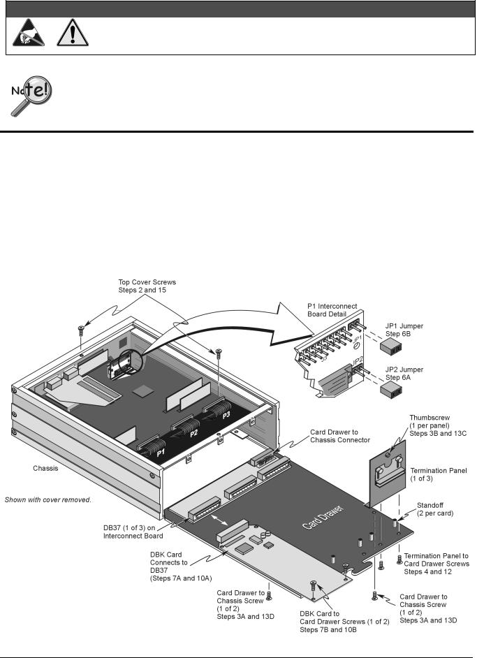
2 – Remove top cover.
If you need to make any change on the LogBook motherboard, you will need to remove the top cover. Otherwise, the cover can remain in place. To remove the top cover, simply remove the two top cover screws and slide the cover free of the device.
LogBook/360, Hardware Setup
QS-360-2 Quick Start, LogBook/360, 10-1-99 |
LogBook User’s Manual |

3 – Remove card drawer.
A.Remove the two screws that hold the card drawer to the chassis.
B.Loosen the three termination panel thumbscrews.
C.Carefully pull the card drawer free of the chassis.
4 – Remove termination panels.
For each termination panel, remove the two screws that mount it to the card drawer, then remove the termination panel.
5 – Determine power requirements.
Depending on the power needs of your system’s DBK cards, you may need to add a power card. Refer to Chapter 2, System Power, in regard to calculating your power requirement.
If the required power is more than the available power (see chapter 2 for calculations), your system will require auxiliary power. One of two power supply cards can be used with LogBook:
•DBK32A – For use with a LogBook, DaqBook, or DaqBoard. It supplies ±15 V.
•DBK33 – For use with Log Book, DaqBook, DaqBoard, or Daq PC-Card. It supplies +5 V and ±15 V.
6 – Configure chassis for power sources.
Proper jumper configuration limits LogBook’s P1 bus to one power source. The P1 bus should never have more than one power source.
The JP1 and JP2 jumpers located on the P1 Interconnect Board inside chassis (see previous figure) control the +5V distribution. Both the JP1 and JP2 jumpers are installed as factory-default.
A. JP2. Only remove the JP2 jumper if cards (on the internal P1 bus) are to be powered from LogBook’s internal PCB.
B. JP1. Only remove the JP1 jumper if a DBK33 is used with the system.
7 – Install power card if necessary.
If you determined in step 5 that additional power was needed, add a DBK32A or DBK33 power card to the chassis. Chapter 2 includes information regarding these power-related cards.
A.Carefully align the power card’s DB37 connector with a DB37 connector on the interconnect board and gently press them together.
B.Mount the power card with two screws into the standoffs on the card drawer.
8 – Configure LogBook/360.
Refer to chapter 1. Note that if a LogBook/360 driver is not available in software, select LogBook/300.
9 – Configure DBK cards.
Configure unique channel addresses with the jumpers on the DBK cards. Some cards have other jumpers and/or DIP switches. Refer to the particular DBK sections of Chapter 5, as needed.
10 – Install DBK cards.
You must use all analog use of all digital cards.
DBK cards in the LogBook/360; unless you have a factory modification that allows the You can not use both analog and digital cards at the same time.
A.Carefully align the DBK card’s DB37 connector with a DB37 connector on the interconnect board and gently press them together (see figure).
B.Mount the DBK card with two screws into the standoffs on the card drawer (see figure).
C.Continue installation of any remaining DBK cards.
LogBook User’s Manual, 10-1-99 |
Quick Start, LogBook/360 QS-360-3 |
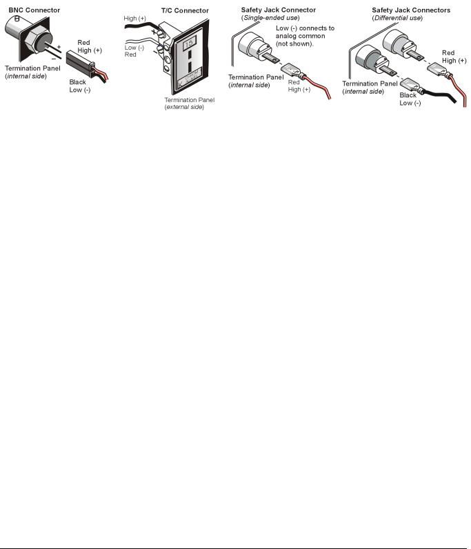
11 – Connect internal signals.
Connect signal inputs from DBK cards to termination panels. DBK cards connect to the termination panels in various ways (see figure and particular DBK sections in manual):
•Single-ended connections use analog common.
•Differential connections require the proper polarity, typically red-to-red for high (+) and black-to-black for low (-).
•For thermocouples, red is generally the low side. Always make sure the T/C connector and wire type match the T/C type used.
12 – Install termination panels.
Mount the termination panels to the card drawer with two screws for each panel.
13 – Install card drawer.
The card drawer slides into the bottom track of the chassis.
A.Hold the card drawer by its handle and tilt it up slightly. Place it on the bottom track of the chassis.
B.Carefully slide the card drawer into the chassis. When it engages the bottom track, level the card drawer and continue inserting it until it engages with the P1 interconnect board.
C.Tighten the three captive thumbscrews holding the termination panels to the chassis.
D.Install the two screws holding the card drawer to the chassis.
14 – Connect external signals.
Connect signal inputs from sensors to termination panels.
15 – Install top cover.
If the top cover was removed, slide it back into place and secure with two screws.
QS-360-4 Quick Start, LogBook/360, 10-1-99 |
LogBook User’s Manual |
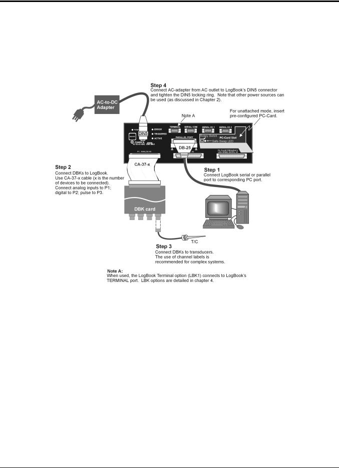
Connect LogBook/360 to PC, External DBKs, and Power*
The following hardware-connection figure and procedure are generic; details vary with system complexity. For “unattached mode,” a pre-configured PC-Card is inserted in the PC-Card slot, and no connection to a PC is made. The following figure illustrates the “attached” mode.
*Note: Connecting LogBook/360 to a PC applies to the “attached mode” only. Many applications will make use of three internal DBK cards only, having no need to attach external DBK cards or modules as discussed in the following text.
LogBook/360 System, “Attached Mode,” Basic Connections
Note: Rear panel connections may be made via terminal blocks, as discussed in the previous section,
Card Drawer Setup.
After verifying that all equipment power is off, hardware connection typically proceeds as follows. Refer to the above figure as needed.
1.Connect LogBook to PC. There are three ways for LogBook to communicate with the host PC. These are: parallel port, serial port, or by physical transportation of the PC-Card. Note that the parallel port method is represented in the previous figure.
a)Parallel port – If using the parallel port, connect the supplied 2-foot parallel port (DB25) cable to PARALLEL PORT on LogBook, and to the corresponding parallel port on the PC. When this method is used, the PC must be set to the ECP mode. See ECP Parallel Port, page 8 for additional information.
b)Serial port – If using the serial port, connect the supplied 6-foot serial-port (DB9) cable to SERIAL PORT on LogBook, and to the corresponding serial port on the PC.
c)PC-Card - As described chapter 1’s PC-Card Swapping section, LogBook does not require an electrical connection to the PC. The PC-Card must be pre-configured [from LogView on the PC] to contain the desired configuration file. Then the PC-Card is inserted into the corresponding slot behind the door on the LogBook’s front panel.
LogBook User’s Manual, 10-1-99 |
Quick Start, LogBook/360 QS-360-5 |
2.Connect LogBook to the DBK cards and modules. For connecting internal DBK cards, refer to the earlier section entitled, Card Drawer Setup.
Most analog DBKs connect to P1; digital DBKs generally connect to P2. Refer to chapter 5 for your particular DBKs and for general DBK installation details.
The CA-37-x cable can daisy-chain several DBKs including the DBK41, which has a built-in P1 bus connection for 10 DBK cards. The x in the cable part number refers to the number of devices that can be connected (a CA-37-1 actually has two DB-37 connectors).
Note: Chapter 1 includes LogBook P1, P2, and P3 Pinouts.
&$87,21
For analog signal inputs via P1, do not exceed -35 VDC or +45 VDC.
Exceeding these limits could result in equipment damage.
3. Connect DBK(s) to transducer(s). Follow instructions for particular DBK as described in chapter 5 and for the particular transducer. Some DBKs can accommodate both BNC and screw-terminal connections.
4. Connect LogBook to a suitable power source, such as a TR-43 AC-to-DC power adaptor or DBK34 vehicle UPS module. DC power sources such as a car batteries must supply 10 to 45 VDC and use the correct DIN5 pinout (see figure). A locking DIN5 connector assures a secure power connection for applications subject to vibration and
thermal stress.
DIN5 Power Input Connector
(As seen on LogBook Front Panel)
Hardware Configuration
Reference Notes:
(1)Refer to chapter 4 in regard to the various LBK options.
(2)Some DBKs require manual configuration. Refer to chapter 5 for specific DBK information.
LogBook's top cover does not need to be removed, except to add or remove an LBK option, or to replace the fuse.
Most LogBook configuration is done via software as described in section, LogBook/360 Device Configuration. Except when using the RS-485 communication option, LogBook configuration does not require you to set jumpers or switches.
Software Installation
Note: The LogBook is supported under Windows95/98 and WindowsNT. Your computer should be a 486 or higher (Pentium® recommended) with at least 16 Mbytes of RAM. 32 Mbytes of RAM is recommended.
Note: Before installing software, you should attach LogBook to the selected port (serial, or
ECP-parallel); and power-on the system.
Install installation CD-ROM (or installation disks, as applicable). Run the Setup.exe and follow screen prompts.
When the software installation is complete, you will be given two options:
•Exit running the configuration utility—if the LogBook is to be used immediately.
•Exit and return to operating system—you can run the configuration later from the control panel.
QS-360-6 Quick Start, LogBook/360, 10-1-99 |
LogBook User’s Manual |

LogBook/360 Device Configuration
A configuration utility is supplied via a control panel applet. The LogBook Configuration applet allows you to add a device, remove a device, or change existing configuration settings. From this same window, you can also access a built-in utility to test the connected device for current setup and performance.
LogBook Configuration can be found in the Windows95/98/NT control panel. This can be navigated to from Window’s desktop Start button:
Start Settings Control Panel
You can enter LogBook Configuration during driver installation or whenever you wish to add, remove or change device configuration settings. The following description applies to either method.
The 1st configuration window will display configured devices in the Device Inventory field based on the port they’re connected to. Devices are indicated by their name and icon. If no devices are currently configured, no devices will appear in this field. (The figure shows the 1st and 2nd configuration windows overlapping.)
LogBook Configuration Windows
The 4 buttons across the bottom of the 1st configuration window (previous figure) are used as follows:
•Properties. Configuration settings for a device can be changed or modified from the corresponding
properties window. To do so, double-click the device icon or single-click the device and then singleclick the Properties button. The 2nd configuration window will appear for the selected device as shown in the previous figure.
•Add. The Add Device button is used to add a device configuration whenever a new device is added to the system. LogView cannot recognize a device unless listed in the configuration window.
•Remove. The Remove button is used to remove a device from the configuration. A device may be removed if it is no longer installed or if the device’s configuration no longer applies.
•Close. The Close button may be used at any time to exit the LogBook Configuration applet.
The 2nd configuration window displays the properties for the selected LogBook. Fields include:
•Device Name is displayed with the default name, numbered successively as configured. This field can be changed to any descriptive name as desired.
•Connection Type can be serial or parallel port.
•Device Connection specifies the port name.
•Protocol is used to set the parallel port protocol (ECP only) or serial protocol (RS-232 or RS-485).
•Device Timeout specifies the number of seconds LogView will be wait for a LogBook response before displaying an error condition.
LogBook User’s Manual, 10-1-99 |
Quick Start, LogBook/360 QS-360-7 |
ECP Parallel Port
To use parallel port communication with an attached LogBook, your PC must support the ECP protocol AND be set in the ECP mode.
PCs made since 1994 probably support the Enhanced Computer Port protocol (ECP). If your parallel port does not support ECP, you can communicate with the LogBook via the RS-232 serial port, or you can add an ECP-compatible ISA board or PC-Card parallel port. Setting the PC to ECP mode varies with different computers. On some computers, you can enter the BIOS Setup utility from Windows Settings or during startup by pressing the F1 function key. The Parallel Port Mode property can be found under the Peripheral Configuration group menu item. If necessary, consult your PC’s documentation or your PC’s manufacturer.
To ensure ECP compatibility after proper setup, use the Test Hardware utility (described on page 9). Before testing, make sure LogBook is properly connected, powered on, and that the Parallel Port Mode is set to ECP (in BIOS Setup).
&$87,21
Making errors in BIOS Setup can disrupt your system’s operation. If test hardware indicates a problem and you have inadequate experience with the BIOS Setup utility, consult your System Administrator or other qualified individual.
Serial Port
If the selected device is connected to a serial port the properties window will include the fields shown in the figure at right. Baud rate can be set from 1200 to 115200 bits per second (default 9600). When all fields have been changed to the desired settings, you can click on one of the following options:
•Apply to store the device configuration. Parameters are not locked in until you click the Apply button. If you make changes and don’t click Apply, clicking the Test button in Test Hardware will yield unexpected errors.
•OK to store the configuration and exit the current property screen.
•Cancel to exit the current screen without storing any changes.
•Test Hardware to test the current device.
LogBook Properties Tab |
Test Hardware Tab |
QS-360-8 Quick Start, LogBook/360, 10-1-99 |
LogBook User’s Manual |
Test Hardware
Before testing LogBook/360:
(a)Verify the device has been properly installed
(b)Make sure the communication cable (serial or parallel) is firmly in place to the proper ports.
(c)Verify the device is powered-on.
Testing the LogBook device might cause the system to hang. If test results are not displayed within 30 seconds, or if the system does not respond properly: reboot the system. Upon power-up, re-enter the LogBook Configuration and ensure the LogBook configuration settings are correct. Change the settings as applicable.
To begin the test, click the Test button. Test results should be displayed within a few seconds.
Test results indicate if the device is online (properly connected, powered on and ready to transfer the data) or offline. If the device is online, Performance Test will display Download and Upload speed rates. These rates represent the maximum speed at which downloading and uploading files can be performed. Actual transfer time will depend on channel configuration and the size of the transfer.
Acquisition Configuration
An acquisition is configured using LogView on a PC and then stored as an acquisition setup file on a PC-Card. The PC-Card may be in an attached LogBook or in the PC to be later manually transferred to an unattached LogBook. The system’s DBK cards are listed; the scan sequence is defined; the trigger conditions are specified, etc.
Reference Note: Configuring the acquisition is described in chapter 3, LogView.
Calibration
Calibration is typically performed automatically through LogView software; however, some DBKs may require manual calibration. LogView’s 2-point calibration fine-tunes the reading’s slope and offset error (mx+b). DBKs working with non-linear sensors typically condition/convert the reading to a linear form. Otherwise, a non-linear analog input signal is difficult to read accurately. Careful use of the calculated channels may yield usable approximations in simple, limited-range conditions.
Reference Note: An example of 2-point calibration is given in the How To… section of chapter 3, LogView.
Appendix A details the calibration methods applicable to DBK16 and DBK43.
LogBook User’s Manual, 10-1-99 |
Quick Start, LogBook/360 QS-360-9 |

QS-360-10 Quick Start, LogBook/360, 10-1-99 |
LogBook User’s Manual |
System Considerations |
1 |
|
|
LogBook Basics……1-1
Introduction ….. 1-1
Front and Rear Panels……1-2 Highlight of Features …… 1-3 LogBook/300 Block Diagram …… 1-4 LogBook/360 Block Diagram …… 1-5 System Software……1-6
Hardware-Related Details……1-7
PC-Card Swapping……1-7 Physical/Environmental Conditions……1-7 Power Supply……1-8 Microprocessor……1-8
Field-Installation Racks and Enclosures……1-8 P1, P2, P3 Port Connectors……1-9
System Design, Setup, and Expansion……1-13
Steps to Review …… 1-13 Expansion Configurations……1-13
LBK Options……1-13
DBK Options……1-14
Mechanical Setup Options……1-16 System Power Considerations……1-17
Operational Features……1-18
Data Acquisition, An Overview……1-18 LogBook System File……1-19 Communications……1-19
Triggering and Scan Timing……1-20 Scan Rate Limitations……1-20
Use of Outputs to Alarm and Control……1-22 Acquisition……1-22
Data Storage and Retrieval……1-22
Reference Notes: Additional system considerations are covered in the following chapters.
SChapter 2, refers to calculating system power and ensuring an adequate power supply.
SChapter 4, details LBK options.
SChapter 5, details DBK expansion options applicable to LogBook.
LogBook Basics
Introduction
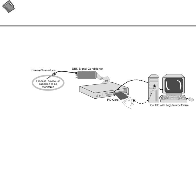
LogBook/300 and LogBook/360 are PC-based data acquisition systems that can work in a stand-alone mode (no PC present), or linked to a PC. They combine onboard intelligence with a removable PC-Card that stores the configuration file and the collected data. LogBooks have many options, most of which are detailed in the LBK and DBK chapters. The PC link can be by serial or parallel port.
LogBook/300, Simple System Setup
The PC-Card holds the configuration file [created by LogView]. The file tells LogBook how to perform a particular acquisition. The PC-Card also holds the acquired data files. The PC can upload to or download from the PC-Card by cable if the PC is attached to LogBook, or by physical transport of the PC-Card from one unit to the other. Multiple configuration files and multiple PC-Cards allow the system to handle complex data acquisition environments with a large number of data-files.
LogBook User’s Manual, 8-30-99 |
System Considerations 1-1 |
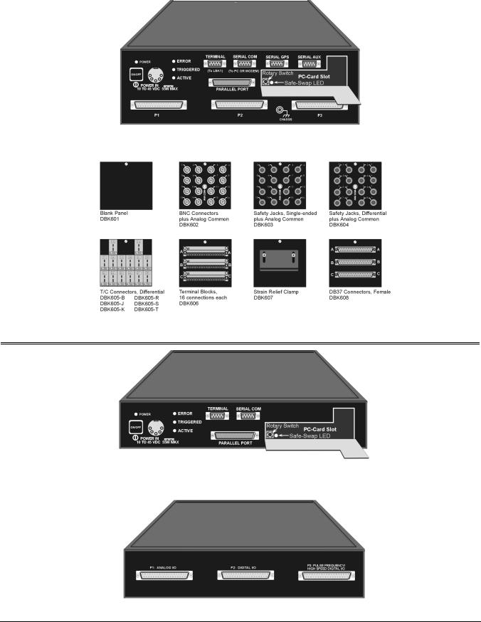
Front and Rear Panels
Note: Descriptions of panel items appear on the following page.
LogBook/360, Front Panel
LogBook/360, Terminal Panels (A combination of 3 make up the rear panel)
LogBook/300, Front Panel
Note: In earlier models, the PC-Card Door has a right-edge hinge (not shown).
LogBook/300, Rear Panel
1-2 System Considerations |
LogBook User’s Manual, 8-30-99 |

LogBook/360 panel items are listed in the following table. 360, except as called out in the following bulleted list:
•Slight differences in the overlay.
•P1, P2, and P3 appear on LogBook/300’s rear panel.
•LogBook/300 has no SERIAL GPS connection.
Not that LogBook/300 panel items are the same as those on the
•LogBook/300 has no SERIAL AUX connection.
•LogBook/300 has no CHASSIS grounding post.
•LogBook/300 does not make use of Terminal Panels.
Switches
ON/OFF |
Depressing the push-button switch turns the power on. |
(interior rotary switch) |
PC-Card door provides access to a rotary switch to set device address when used in an RS-485 network. |
|
|
Connectors |
|
POWER IN |
This locking DIN5 input connector accepts +10 to +45 VDC. |
PARALLEL PORT |
This DB-25 plug is a parallel port connector to a host PC (set to ECP mode) |
TERMINAL PORT (TO LBK1) |
This DB-9 socket is a serial port connector for the LBK1 remote control panel (user-interface terminal). |
SERIAL COMM |
This DB-9 male serial COM port connects to a host PC or modem. |
(TO PC OR MODEM) |
|
SERIAL GPS |
LogBook/360 only. This DB-9 male serial port option connects to a Global Positioning System. |
(LogBook/360 Only) |
|
SERIAL AUX |
LogBook/360 only. This DB-9 male serial port option connects to optional auxiliary devices. |
(LogBook/360 Only) |
|
P1 - ANALOG I/O |
Provides 16 analog input channels, 3 TTL inputs, and various signals for driving expansion cards. |
P2 - DIGITAL I/O |
Provides 3 8-bit TTL programmable I/O ports and external interrupt input. |
P3 - PULSE FREQUENCY / |
Provides 4 16-bit counters, 4 analog outputs, and 16 high-speed digital I/O. |
HIGH-SPEED DIGITAL I/O |
|
(PC-Card door, no label) |
Door provides access to PCMCIA connector—for removable PC-Card memory devices. |
|
|
Indicator LEDs |
|
POWER |
LED lights when power is applied to LogBook and the power switch is depressed into the ON position. |
ERROR |
LED lights steady ON when a routine error occurs (e.g. disk full). |
|
LED flashes for fatal errors; refer to Hardware Errors in Appendix B. No data can be acquired until error is |
|
cleared. |
TRIGGERED |
LED lights after trigger event and during an A/D scan sequence. |
ACTIVE |
LED lights to show that LogBook is ready to begin a scan at the next trigger event. |
Safe-Swap Light |
LED lights when it is safe to swap PC-Cards. |
(interior green LED) |
|
Highlight of Features
LogBooks can be left unattended for long testing periods and used in environments not suitable for PCs. With the use of PC-Cards, one PC can support several LogBooks. Other LogBook features include:
•Onboard processor capable of real-time data reduction and system control in stand-alone mode
•Non-volatile storage of configuration files and samples via removable, transportable PC-Cards
•4 MB RAM onboard, expandable to 16 MB
•100 kHz 16-bit Analog-to-Digital Conversion
•8 differential, 16 single-ended inputs; expandable to 256 input channels via DBK cards
•7 gain/input ranges, unipolar and bipolar
•40 digital I/O lines, expandable to 208
•4 pulse-counting inputs
•Gain and unipolar/bipolar settings are programmed in real time (10 µs max)
•Scan-sequence memory (1024 analog channels plus 128 digital channels) for any combination of channels/gains
•Input power: 10 to 45 VDC (AC adapter included)
•Several LBK options (listed on page 1-13, and detailed in chapter 4)
•Several DBK options (listed on page 1-14 detailed in chapters 2 and 5)
LogBook User’s Manual, 8-30-99 |
System Considerations 1-3 |
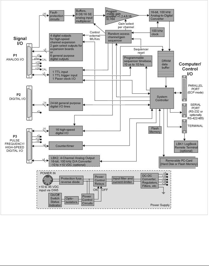
LogBook/300 Block Diagram
1-4 System Considerations |
LogBook User’s Manual, 8-30-99 |

LogBook/360 Block Diagram
LogBook User’s Manual, 8-30-99 |
System Considerations 1-5 |

The following components are represented in the previous block diagrams. Certain items apply only to LogBook/360, as noted.
•Removable PC-Card. A 12-520 MB capacity holds the software, operating system, user configurations and the acquired data. The PC-Card is at the center of LogBook operations.
A PC-Card [pre-programmed by LogView] ensures an unattached LogBook comes up properly.
•Power Supply. The internal power supply accepts an input of 10 to 45 VDC and supplies filtered regulated voltages to its internal circuits and to accessories connected via P1/2/3. An external AC adapter for all standard voltages is included with the system.
•System Controller. A microprocessor chip is used within LogBook with either 4 MB (standard) of RAM or 16 MB (optional). A field-upgradeable 512 KB Flash memory is used to store the system startup code, self-diagnostics, and FPGA configuration.
•Analog Input via P1. 16 main channels that can each accommodate 16 sub-channels via multiplexing for a total of 256 analog input channels. Fault protection and buffer circuits prevent overloads and cross-channel noise due to impedance mismatch.
•A/D Converter. The A/D converter uses 16-bit resolution @ 100 kHz sample rate.
•Digital I/O. 16 high-speed digital inputs via P3, three 8-bit TTL programmable I/O ports via P2, three TTL inputs via P1. Note that LogBook/360 has P1, P2, and P3 connectors on the motherboard that are connected [by ribbon cable] to secondary P1, P2, and P3 connectors [located on the chassis front panel]. LogBook/300’s P1, P2, and P3 are located on the rear panel.
•LBK2 Analog Output (optional): This option provides four channels of analog output, 16-bit @ 100 kHz @ ±10 VDC.
•LogBook/360 only, Interconnect Board, Card Drawer (for three DBK cards), and three Terminal Panels.
•Computer/Control/I/O – Includes: PARALLEL PORT (ECP Mode), SERIAL PORT (for RS-232 or RS-422/485), TERMINAL PORT (for LBK1 LogBook Remote Terminal option). In addition, for LogBook/360 only, there is a COM Expansion Card with two serial ports (SERIAL AUX and SERIAL GPS). These two ports are for connecting auxiliary serial devices, such as a Global Positioning System.
System Software
LogBook software includes LogView, Upload Scheduler (optional), DIAdem-View, and PostView.
LogView and the Upload Scheduler are detailed in Chapters 3 and 4, respectively. DIAdem-View is discussed in it’s own, separate user documentation. Appendix F covers PostView, which is similar to DIAdem-View, but much more limited. Each of these programs is discussed briefly below.
•LogView is a ready-to-use Windows program for data acquisition and logging. The program provides a means of selecting channels, gains, transducer types, and various parameters. After setting up the configuration on the PC, you must download the configuration file to LogBook’s PC-Card. LogBook then uses the PC-Card to start the pre-configured acquisition. During an acquisition, LogView can display channel values in a spreadsheet, bargraph, analog meter, or digital indicator.
LogBook data can be uploaded to your PC in various data formats (Excel™, SnapMaster™, MATLAB™, DASYLab™, Lotus®, Quattro, and ASCII) for compatibility with virtually all post-acquisition analysis software. LogView is detailed in chapter 3.
•DIAdem-View provides a means of viewing and analyzing data via interactive graphics. The basic DIAdem-View can be enhanced with optional software modules. Refer to the separate DIAdem User’s Manual and the DIAdem on-line help for detailed information.
•PostView is a post-acquisition waveform-display program. The program permits the simultaneous viewing of up to 16 pre-recorded data channels. PostView allows you to expand, contract and auto-scale waveforms, and scroll forward or backward on the time line. PostView is detailed in Appendix F.
•Upload Scheduler is an application that exists as part of the LogBook/Modem option. Upload Scheduler allows you to configure upload events for one or more LogBooks. A scheduled event can be configured to execute one time, or periodically, with no post-configuration intervention by the user.
The Upload Scheduler is detailed in chapter 4.
1-6 System Considerations |
LogBook User’s Manual, 8-30-99 |
Hardware-Related Details
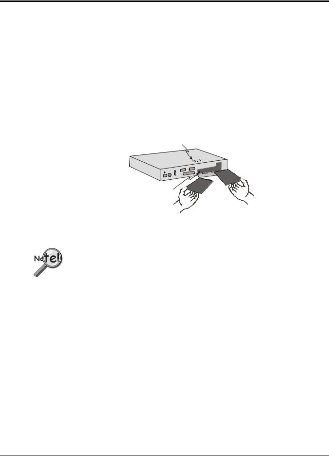
PC-Card Swapping
After the initial setup, you can interact with LogBook with PC-Cards. A safe-swap LED (inside the PC-Card access door) lights when it is safe to change PC-Cards. You can also interact with LogBook using the LBK1 Remote Terminal Panel option (discussed in chapter 4). The LBK1 option provides limited LogBook control without use of the LogView program.
Note: during operation, LogView is the primary system interface for control and configuration.
You can change PC-Cards to load setup files, replace full cards, or transport data to an unattached PC. When the PC-Card door is opened, a detector starts a preparatory routine to clean up files on the installed disk. Within a few seconds, a green LED indicates it is safe to swap PC-Cards. Swapping should be done quickly to prevent gaps in the recorded data. 4 MB RAM provides about
10 seconds at 100 kHz and 1.75 minutes at 10 kHz. 16 MB RAM provides over a minute at 100 kHz and about 12 minutes at 10 kHz for one-channel scans.
Internal P C -Ca rd socke t (insert
card carefully to e nsure goo d co nne ction an d prevent pin da m ag e)
Green LED indicates ready for card exchange
P C -Ca rd s - re m ove on e an d insert ano ther
Swapping PC-Cards in a LogBook/300
Note: Some models have PC-Card doors with right-edge hinges (not shown).
SSwapping time is measured from when the door opens. Keep door closed unless you are in the process of swapping cards.
SPC-Cards must be pre-configured by LogView—if anticipating the need for multiple cards, download the exact SAME ACQUISITION SETUP FILE to each PC-Card.
SThe PCMCIA slot accepts a Type I, II, or III hard-disk card or ATA flash-memory solid-state card.
Physical/Environmental Conditions
LogBook/300 Dimensions: 8½ × 11 × 1-3/4 in. (216 × 279 × 44 mm). This enclosure has the same footprint as the DBK modules for easy stacking of units.
LogBook/360 Dimensions: 14 × 11 × 3-7/16 in. (330 × 279 × 84 mm). The 11 inch width provides for convenient stacking of DBK modules.
Operating temperature/humidity: 32° to 122°F (0° to 50°C) @ 0 to 95% RH, non-condensing. Operation of the unit in environments exceeding these limits requires that a temperature-regulated enclosure).
Storage temperature: 32° to 176°F (0° to 80°C). The standard case is rugged but not designed for immersion. Special enclosures are available for harsh environments.
All connectors, including the power connector, are locking. The D-sub connectors have thumbscrews and the DIN5 power connector has a twist-lock ring to ensure solid connections are maintained.
LogBook User’s Manual, 8-30-99 |
System Considerations 1-7 |

Power Supply
Power Input Connector
LogBook’s front panel has a socket DIN5 connector to access power (10 to 45 VDC at 0.3 to 7.0 A). The included AC-to-DC adapter (TR-43) is recommended. However, various power supplies if properly wired (see figure) can be used.
Internal Power Supply
LogBook’s power supply is a switching design (pulse-width modulated). The input will accept 10-45 VDC with a current range of 0.4 to 7.0 A. The input is protected by an 8 A fast-blow fuse. The fuse will open if the input voltage is applied with the wrong polarity.
The power supply provides the necessary voltages to P1, P2, and P3 for use by DBKs. You can refer to the P1, P2, and P3 pinouts (in this chapter) and to chapter 2, System Power, for detailed information.
AC-to-DC Adapter
An AC-to-DC adapter (TR-43) is provided with LogBook. This external, switching supply runs on US/Europe/Japan input voltage ranges. Output voltage and power are sufficient to run the system in most applications. Input: 90-260 V @ 50-60 Hz. Output: 15 VDC @ 2.3 A. If more power is needed, a
24 VDC, 2.2 A adapter (TR-44) is available as an option.
UPS
DBK34 is an optional uninterruptable Power Supply (UPS) that allows LogBook to operate for at least 30 minutes without any other source of power. This capability allows operation, for example, during starting and after switch-off of an automobile. Control circuits keep the on-board batteries fully charged when possible. For more information on the DBK34, refer to chapter 2, System Power.
Power Failure and Recovery
When power fails, LogBook preserves as much data as possible. LogBook also attempts to keep PC-Card file formats and structures intact. Due disk drive latencies, power-supply limitations, and DOS file structure, it may not be possible to finish the shutdown process before a complete loss of power occurs.
Note: Recovery will not occur when power is restored, unless the shutdown process was completed.
Note: The DBK34 Vehicle UPS is recommended for applications that are subject to power problems, or are intolerant to down time. DBK34 is discussed in chapter 2, System Power.
Microprocessor
LogBook uses a high-integration microprocessor with up to 16 MB of memory (4 MB standard). The microprocessor and a Field-Programmable Gate Array (FPGA) control all LogBook operations including real-time control. Internal flash memory is used instead of EPROMs. This allows for field upgrades of virtually all functions, including FPGA circuitry. Most software will be read from the disk drive.
Field-Installation Racks and Enclosures
A special rack (p/n Mount1) is available to attach the LBK1 (Remote Terminal Panel option) to the top of LogBook. The LBK1 section of chapter 4 provides details. For applications in harsh environments, a special enclosure can be used to shield the unit from water and thermal stress. Consult your sales rep or factory for details.
1-8 System Considerations |
LogBook User’s Manual, 8-30-99 |
Loading...