


CN7500

2007-03-08
5011654002-CN72
CN7500/CN7800 Temperature Controller
Instruction Sheet
Thank you very much for choosing Omega Engineering Series CN7500/CN7800 Temperature/Process Controller.
Please read this instruction sheet before using your controller to ensure proper operation and please keep this
instruction sheet handy for quick reference.
1 Precaution
DANGER! Caution! Electric Shock!
1. Do not touch the AC terminals while the power is supplied to the controller to prevent an electric shock.
2. Make sure the power is disconnected while checking the unit inside.
3. The symbol
REINFORCED INSULATION (equivalent to Class II of IEC 536).
WARNING!
Mount the controller in a location that will not be subject to excessive temperature, shock, or vibration.
All models are designed for mounting in an enclosed panel.
1. Always use recommended solder-less terminals: Fork terminal with isolation (M3 screw, width is 7.0mm
(6.0mm for 32B Series), hole diameter 3.2mm). Screw size: M3 x 6.5 (With 6.8 x 6.8 square washer). Screw
size for 32B Series: M3 x 4.5 (With 6.0 x 6.0 square washer). Recommended tightening torque: 0.4 N.m
(4kgf.cm). Applicable wire: Solid/twisted wire of 2 mm
properly.
2. Do not allow dust or foreign objects to fall inside the controller to prevent it from malfunctioning.
3. Never modify or disassemble the controller.
4. Do not connect anything to the “No used” terminals.
5. Make sure all wires are connected to the correct polarity of terminals.
6. Do not install and/or use the controller in places subject to: Dust or corrosive gases and liquid, high humidity
and high radiation, vibration and shock, high voltage and high frequency
7. Power must be off when wiring and changing a temperature sensor.
8. Be sure to use compensating wires that match the thermocouple types when extending or connecting the
thermocouple wires.
9. Please use wires with resistance when extending or connecting a platinum resistance sensor (RTD).
10. Please keep the wire as short as possible when wiring a platinum resistance sensor (RTD) to the controller
and please route power wires as far as possible from load wires to prevent interference and induced noise.
11. This controller is an open-type unit and must be placed in an enclosure away from high temperature,
humidity, dripping water, corrosive materials, airborne dust and electric shock or vibration.
12. Please make sure power cables and signals from instruments are all installed properly before energizing the
controller, otherwise serious damage may occur.
13. Please do not touch the terminals in the controller or try to repair the controller when power is applied to
prevent an electric shock.
indicates that this Controller is protected throughout by DOUBLE INSULATION or
2
, 12AWG to 24AWG. Please be sure to tighten them
14. Wait at least one minute after power is disconnected to allow capacitors to discharge, and please do not
touch any internal circuit within this period.
15. Do not use acid or alkaline liquids for cleaning. Please use a soft, dry cloth to clean the controller.
16. This instrument is not furnished with a power switch or fuse. Therefore, if a fuse or power switch is required,
install the protection close to the instrument. Recommended fuse rating: Rated voltage 250 V, Rated current
1 A. Fuse type: Time-lag fuse
17. Note: This controller does not provide overcurrent protection. Use of this product requires that suitable
overcurrent protection device(s) must be added to ensure compliance with all relevant electrical standards
and codes. (Rated 250 V, 15 Amps max). A suitable disconnecting device should be provided near the
controller in the end-use installation.
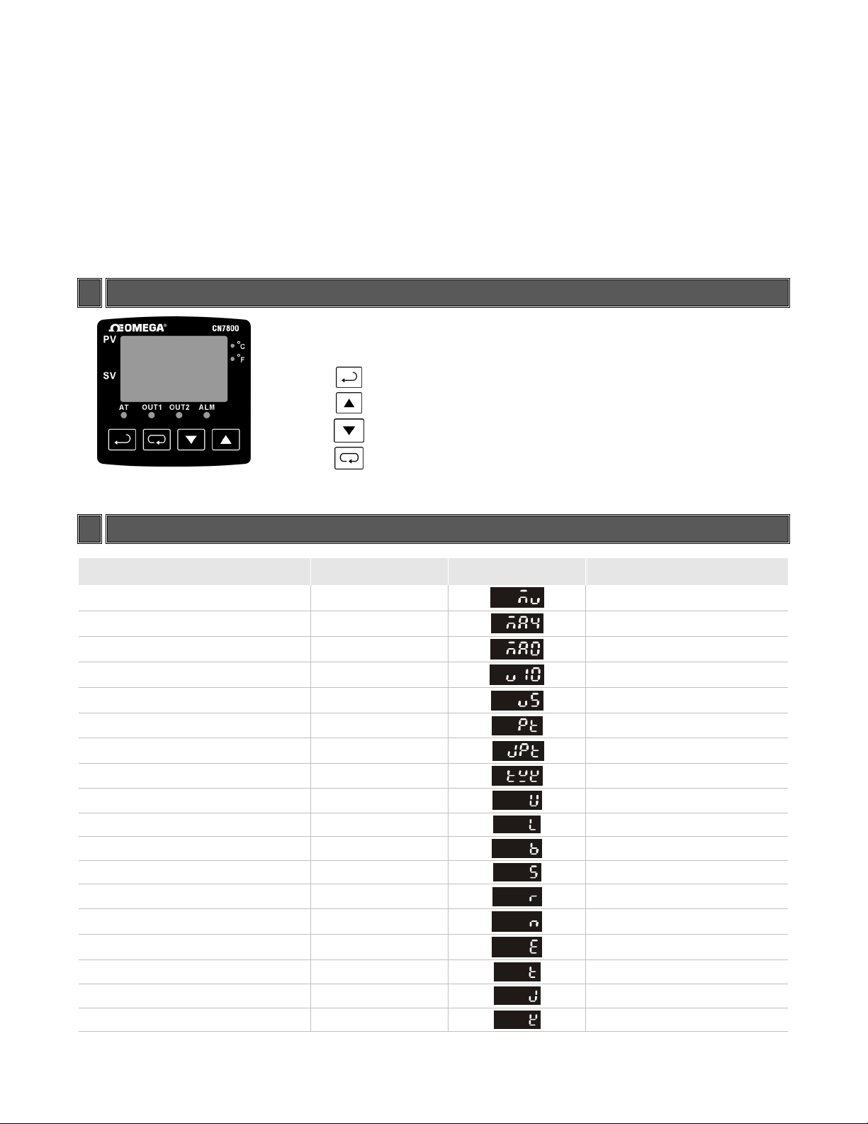
2 Display, LED and Pushbuttons
displays process value
PV
displays setpoint value.
SV
INDEX: advances the display to the next menu item
UP ARROW: Increments a value or changes a menu item.
DOWN ARROW: Increments a value or changes a menu item.
Note: CN7500 Series does not support an additional alarm output, however, the user can set 2nd output as alarm mode.
ENTER: stores the value or item change.
3 Temperature Sensor Type and Temperature Range
Input Temperature Sensor Type Register Value LED Display Temperature Range
0 ~ 50mV Analog Input 17
4 ~ 20mA Analog Input 16
0 ~ 20mA Analog Input 15
0V ~ 10V Analog Input 14
0V ~ 5V Analog Input 13
Platinum Resistance (Pt100) 12
Platinum Resistance (JPt100) 11
Thermocouple TXK type 10
Thermocouple U type 9
Thermocouple L type 8
Thermocouple B type 7
Thermocouple S type 6
Thermocouple R type 5
Thermocouple N type 4
Thermocouple E type 3
Thermocouple T type 2
Thermocouple J type 1
Thermocouple K type 0
-999 ~ 9999
-999 ~ 9999
-999 ~ 9999
-999 ~ 9999
-999 ~ 9999
-200 ~ 600
-20 ~ 400
-200 ~ 800
-200 ~ 500
-200 ~ 850
100 ~ 1800
0 ~ 1700
0 ~ 1700
-200 ~ 1300
0 ~ 600
o
-200 ~ 400
-100 ~ 1200
-200 ~ 1300
o
o
C
o
o
o
o
o
o
C
C
o
C
C
C
C
C
o
C
o
o
C
C
C
C
Note 1: An internal precision resistor for the current input is built-in, please refer to item 15, How To Set Up Current Input.
Note 2:
type, allow the decimal point position to be specified.
The default range of analog input is -999 ~ 9999. For example, when a 0~20mA analog input is selected as the input
temperature sensor type, -999 indicates 0mA and 9999 indicates 20mA. If change the input range to 0 ~ 2000, then 0 indicates
0mA and 2000 indicates 20mA. One display scale is equal to 0.01mA.
(in the operation mode) specifies the decimal point position. All input types except thermocouple B, S, and R
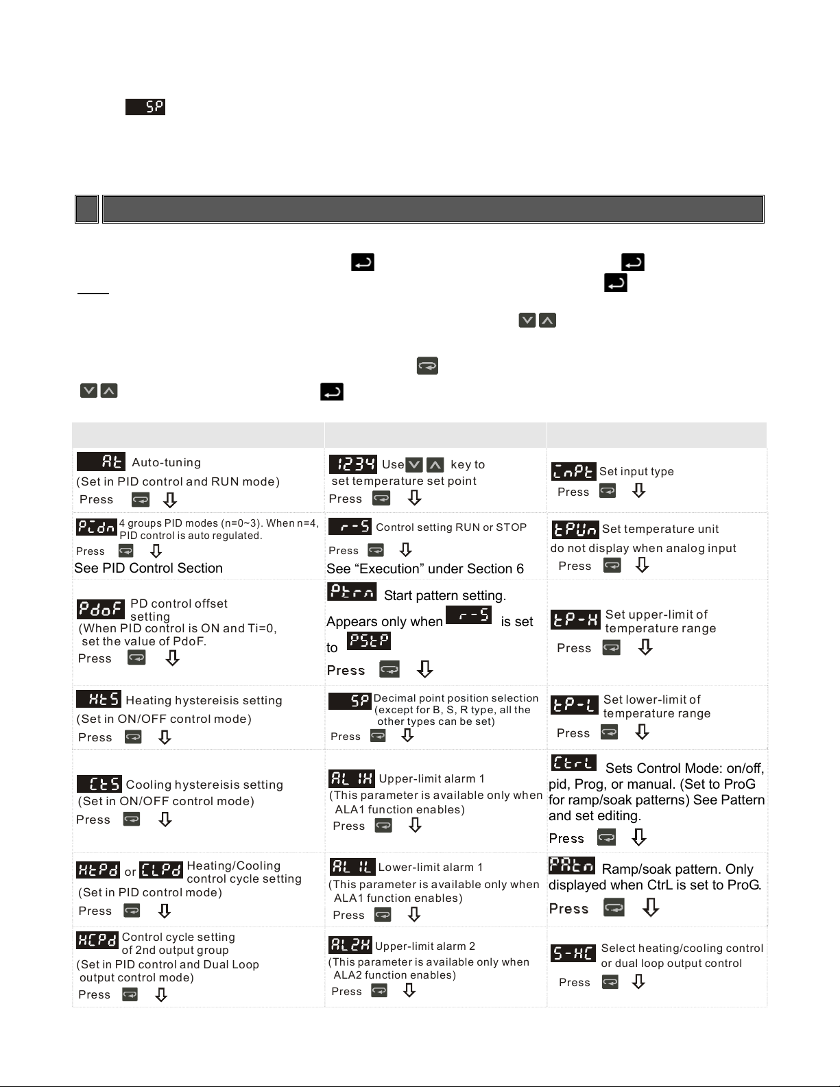
4 Operation
There are three modes of operation: operation, regulation and initial setting. When power is applied, the controller
will default to the operation mode. Press the
than 3 seconds, the controller will switch to the initial setting mode. Pressing the key while in the
more
regulation mode or initial setting mode, forces the controller to return to the operation mode. PV/SV: Sets the
temperature set point and displays the temperature process value. Use
point.
Setting method: While in any function mode, press the
keys to change settings. Press key to save the changes. Menu items are listed below.
Regulation Mode Operation Mode Initial Setting Mode
Auto-tuning
(Set in PID control and RUN mode)
Press
4 groups PID modes (n=0~3). When n=4,
PID control is auto regulated.
Press
See PID Control Section
set temperature set point
Press
Press
See “Execution” under Section 6
key to switch to regulation mode. If the key is pressed for
keys to set the temperature set
key to select the desired function and use the
Use key to
Control setting RUN or STOP
do not display when analog input
Press
Press
Set input type
Set temperature unit
PD control offset
(When PID control is ON and Ti=0,
set th e va lue of Pdo F.
Press
(Set in ON/OFF control mode)
Press
(Set in ON/OFF control mode)
Press
(Set in PID control mode)
Press
(Set in PID control and Dual Loop
output control mode)
Press
setting
Heati ng hystereisis setting
Cooling hystereisis setting
or
Control cycle setting
of 2nd output group
Heating/Cooling
control cycle setting
Start pattern setting.
Appears only when
to
is set
Press
Set upper-limit of
temperature range
Decimal point position selection
(except for B, S, R type, all the
other types can be set)
Press
Upper-limit alarm 1
(This parameter is available only when
ALA1 function enables)
Press
Press
pid, Prog, or manual. (Set to ProG
for ramp/soak patterns) See Pattern
and set editing.
Set lower-limit of
temperature range
Sets Control Mode: on/off,
Lower-limit alarm 1
(This parameter is available only when
ALA1 function enables)
Press
Upper-limit alarm 2
(This parameter is available only when
ALA2 function enables)
Press
displayed when CtrL is set to ProG.
Ramp/soak pattern. Only
Select heating/cooling control
or dual loop output control
Press
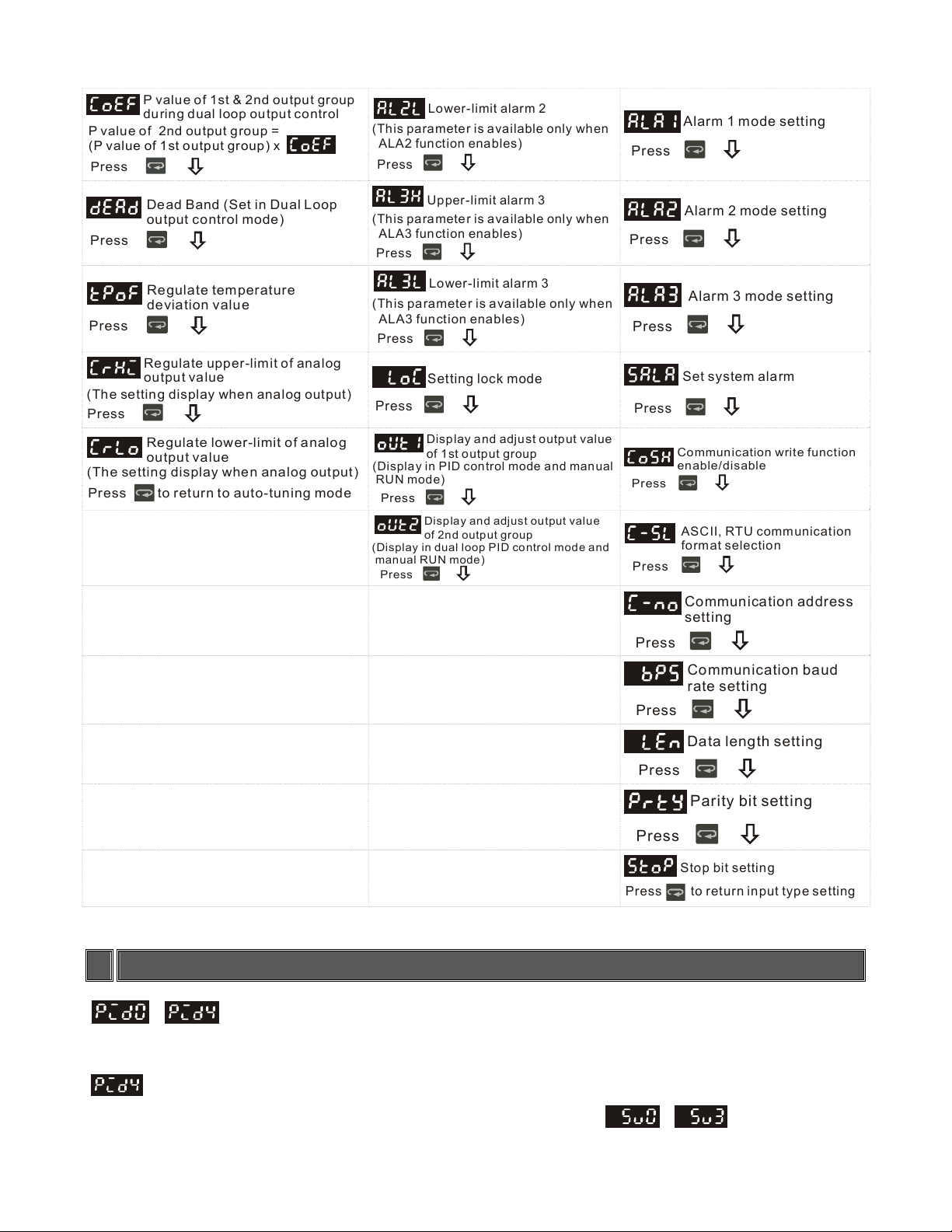
P value of 1st & 2nd output group
during dual loop output control
P value of 2nd output group =
Press
Lower-limit alarm 2
(This parameter is available only when
x (P value of 1st output group)
ALA2 function enables)
Press
Press
Alarm 1 mode setting
Dead Band (Set in Dual Loop
output control mode)
Press
Regulate temperature
deviation value
Press
Regulate upper-limit of analog
output value
(The setting display when analog output)
Press
Regulate lower-limit of analog
(The setting display when analog output)
Press
output value
to return to auto-tuning mode
(This paramete r is available only when
ALA3 function enables)
Press
(This parameter is available only when
ALA3 function enables)
Press
Press
(Display in PID control mode and manual
RUN mode)
Press
(Display in dual loop PID control mode and
manual RUN mode)
Press
Upper-limit alarm 3
Lower-limit alarm 3
Setting lock mode
Display and adjust output value
of 1st output group
Display and adjust output value
of 2nd output group
Press
Press
Press
Press
Press
Press
Alarm 2 mode setting
Alarm 3 mode setting
Set system alarm
Communication write function
enable/disable
ASCII, RTU communication
format selection
Communication address
setting
Communication baud
Press
rate setting
Data length setting
Press
Parity bit setting
Press
Pr ess to ret urn input ty p e se t ting
1 Scale = 2.8uA = 1.3mV for tuning output value
Stop bit setting
5 PID Control
~ : PIDn, n = 0 ~ 4, found in the regulation mode, four groups of user-defined PID settings and
an auto tuning function are available. Each group contains a set value, proportional band, integral time, derivative
time, and integral deviation settings (P, I, D, IOF) for PID control.
: n = 4, is the auto PID parameter. The controller will automatically select a most useful PID parameter
based on current temperature setting. Displayed SV values correspond to
~
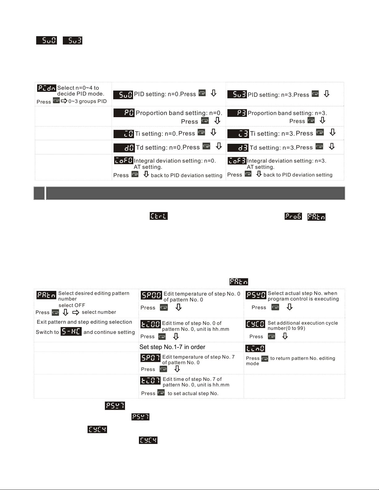
~ : is the temperature setting which corresponds to the selected PID parameter via user-defined
or AT (auto-tuning).
After AT(auto-tuning) the values will be stored.
PID mode selection (regulation mode): any one of four PID modes (n=0~3) can be selected. When n=4, the unit
will perform auto-tuning.
Select n=0~4 to
decide PID mode.
Press
0~3 groups PID
PID setting: n=0.
Proportion band setting: n=0.
Press
Press
PID setting: n=3.
Proportion band setting: n=3.
Press
Press
Press
Ti setting: n=0.
Td setting: n=0.
Integral deviation setting: n=0.
AT setting.
back to PID deviation setting
Press
Press
Press
Ti setting: n=3.
Td setting: n=3.
Integral deviation setting: n=3.
AT se t t i n g.
back to PID deviation setting
Press
Press
6 Pattern and Set Editing (Ramp and Soak Programming)
Description of Function and Parameters Setting:
To set-up or edit the ramp/soak function,
immediately follow in the menu list.
The Ramp and Soak function is supported by 8 different patterns (Pattern No. 0 ~ 7). Each pattern contains 8
steps (step No. 0 ~ 7) for set point and execution time, one Link Pattern parameter, one Cycle parameter and one
Actual Step parameter.
The set point (SV) should reach temperature X after the execution time T. The default of step No. 0 is soak control.
The unit will control the temperature (PV) to reach the set point X and then keep the temperature at set point X.
The execution time T is determined by step No, 0.
The following display is an example of operation of pattern No. 0.
Select desired editing pattern
number
select OFF
Press
Exit pattern and step editing selection
Sw it ch to and co ntinu e setting
select number
Press
Press
Set step No.1-7 in order
Press
Pr es s to set actu al step No.
in the initial setting mode must be set to . Will
PAtn where n = 0-7.
Edit temperature of step No. 0
of pattern No. 0
Edit t i me of s tep N o. 0 of
pattern No. 0, unit is hh.mm
Edit t emperature o f ste p No. 7
of pattern No. 0
Pres s to retu rn pa tt ern No. editi ng
mode
Select actual step No. when
program control is executing
Press
Set additional execution cycle
number(0 to 99)
Press
Set link pattern, OFF indicates
the program end
Edit time of step No. 7 of
pattern No. 0, unit is hh.mm
Actual Step Parameter : Offered for each pattern (0-7), the user can select to execute only certain steps
in the pattern. For example, when
Cycle Parameter
: Offered for each pattern (0-7), the cycle parameter will execute the selected pattern X
amount of times. For example, when
is set to 2, pattern No 7 will only execute steps 0 through 2.
is set to 2, pattern No. 4 will cycle through the steps and then cycle
through the steps 2 more times.
 Loading...