


 User’sGuide
Shop online at
www.omega.com e-mail: info@omega.com
FMA 5400/FMA 5500
Mass Flow Controllers

|
OMEGAnet® Online Service |
Internet e-mail |
|
|
|
www.omega.com |
info@omega.com |
|
|
|
|
|
|
Servicing North America: |
|
USA: |
One Omega Drive, Box 4047 |
|
|
ISO 9001 Certified |
Stamford CT 06907-0047 |
|
|
|
|
Tel: (203) 359-1660 |
FAX: (203) 359-7700 |
|
|
e-mail: info@omega.com |
|
Canada: |
976 Bergar |
|
|
|
|
Laval (Quebec) H7L 5A1 |
|
|
|
Tel: (514) 856-6928 |
FAX: (514) 856-6886 |
|
|
e-mail: info@omega.ca |
|
For immediate technical or application assistance:
USA and Canada: Sales Service: 1-800-826-6342 / 1-800-TC-OMEGA® Customer Service: 1-800-622-2378 / 1-800-622-BEST® Engineering Service: 1-800-872-9436 / 1-800-USA-WHEN® TELEX: 996404 EASYLINK: 62968934 CABLE: OMEGA
Mexico: |
En Espan˜ ol: (001) 203-359-7803 |
e-mail: espanol@omega.com |
|
FAX: (001) 203-359-7807 |
info@omega.com.mx |
|
Servicing Europe: |
|
Benelux: |
Postbus 8034, 1180 LA Amstelveen, The Netherlands |
|
|
Tel: +31 (0)20 3472121 |
FAX: +31 (0)20 6434643 |
|
Toll Free in Benelux: 0800 0993344 |
|
|
e-mail: sales@omegaeng.nl |
|
Czech Republic: |
Rude arm-dy 1868, 733 01 Karvin- 8 |
|
|
Tel: +420 (0)59 6311899 |
FAX: +420 (0)59 6311114 |
|
Toll Free: 0800-1-66342 |
e-mail: info@omegashop.cz |
France: |
11, rue Jacques Cartier, 78280 Guyancourt, France |
|
|
Tel: +33 (0)1 61 37 29 00 |
FAX: +33 (0)1 30 57 54 27 |
|
Toll Free in France: 0800 466 342 |
|
|
e-mail: sales@omega.fr |
|
Germany/Austria: |
Daimlerstrasse 26, D-75392 Deckenpfronn, Germany |
|
|
Tel: +49 (0)7056 9398-0 |
FAX: +49 (0)7056 9398-29 |
|
Toll Free in Germany: 0800 639 7678 |
|
|
e-mail: info@omega.de |
|
United Kingdom: |
One Omega Drive, River Bend Technology Centre |
|
ISO 9002 Certified |
Northbank, Irlam, Manchester |
|
|
M44 5BD United Kingdom |
|
|
Tel: +44 (0)161 777 6611 |
|
|
Toll Free in United Kingdom: 0800-488-48 FAX: +44 (0)161 777 6622 |
|
|
e-mail: sales@omega.co.uk |
|
It is the policy of OMEGA to comply with all worldwide safety and EMC/EMI regulations that apply. OMEGA is constantly pursuing certification of its products to the European New Approach Directives. OMEGA will add the CE mark to every appropriate device upon certification.
The information contained in this document is believed to be correct, but OMEGA Engineering, Inc. accepts no liability for any errors it contains, and reserves the right to alter specifications without notice.
WARNING: These products are not designed for use in, and should not be used for, patient-connected applications.
TABLE OF CONTENTS
1. |
UNPACKING THE FMA 5400/5500 MASS FLOW CONTROLLER |
............1 |
||
|
1.1 |
Inspect Package for External Damage.............................................. |
1 |
|
|
1.2 |
Unpack the Mass Flow Controller....................................................... |
1 |
|
|
1.3 |
Returning Merchandise for Repair..................................................... |
1 |
|
2. |
INSTALLATION.................................................................... |
2 |
||
|
2.1 |
Primary Gas Connections................................................................. |
2 |
|
|
2.2 |
Electrical Connections...................................................................... |
2 |
|
|
|
2.2.1 |
Valve Control Configuration............................................ |
4 |
|
|
2.2.2 |
Remote LCD Readouts................................................... |
4 |
|
|
2.2.3 |
Panel Mounting Readouts.............................................. |
5 |
3. |
PRINCIPLE OF OPERATION.................................................... |
5 |
||
4. |
SPECIFICATIONS.................................................................. |
6 |
||
|
4.1 |
CE Compliance................................................................................ |
8 |
|
|
4.2 |
Flow Capacities................................................................................ |
8 |
|
5. |
OPERATING INSTRUCTIONS................................................... |
9 |
||
|
5.1 |
Preparation and Warm Up................................................................ |
9 |
|
|
5.2 |
Flow Signal Output Readings.............................................................. |
10 |
|
|
5.3 |
Swamping Condition........................................................................... |
10 |
|
|
5.4 |
Setpoint Reference Signal.................................................................. |
10 |
|
|
5.5 |
Valve OFF Control (Open Collector NPN Compatible).......................... |
11 |
|
|
5.6 |
Valve Test/Purge................................................................................. |
12 |
|
6. |
MAINTENANCE.................................................................... |
12 |
||
|
6.1 |
Introduction........................................................................................ |
12 |
|
|
6.2 |
Flow Path Cleaning.............................................................................. |
13 |
|
|
|
6.2.1 |
Cleaning the Inlet Filter Screen in FMA Models................. |
13 |
|
|
6.2.2 |
Valve Maintenance for FMA 5400/5500 |
13 |
|
|
|
Series Max. Flow 10, 50 and 100 L/min............................ |
|
7. |
CALIBRATION PROCEDURES.................................................... |
15 |
||
|
7.1 |
Flow Calibration................................................................................... |
15 |
|
|
7.2 |
Calibration of FMA 5400/5500 Mass Flow Controllers....................... |
16 |
|
|
|
7.2.1 |
Connections and Initial Warm Up................................... |
16 |
|
|
7.2.2 |
Zero Adjustment............................................................. |
16 |
|
|
7.2.3 |
SPAN Adjustment........................................................... |
17 |
|
|
7.2.4 |
Linearity Adjustment...................................................... |
17 |
|
7.2.4.1 |
Disable Solenoid Valve in FMA 5400/5500 |
|
|
|
Series Max. Flow FMA 10, 50 and 100 L/min................. |
17 |
|
7.2.4.2 |
Open Motorized Valve in FMA 5400/5500 |
|
|
|
Series Max. Flow 200, 500 and 1000 L/min...................... |
17 |
|
7.2.5 |
Connections and Initial Warm Up.................................. |
18 |
|
7.2.6 |
ZERO Adjustment.......................................................... |
18 |
|
7.2.7 |
25% Flow Adjustment..................................................... |
18 |
|
7.2.8 |
50% Flow Adjustment..................................................... |
18 |
|
7.2.9 |
75% Flow Adjustment.................................................... |
19 |
|
7.2.10 |
100% Flow Adjustment.................................................. |
19 |
|
7.2.11 |
Valve Adjustment............................................................ |
19 |
|
7.2.11.1 |
Valve Adjustment for FMA 5400/5500 |
19 |
|
|
Series Max. Flow 10, 50 and 100 L/min......................... |
|
|
7.2.11.2 Valve Adjustment for FMA 5400/5500 |
19 |
|
|
|
Series Max. Flow 200, 500 and 1000 L/min.................... |
|
|
7.2.12 Full Scale Flow Adjustment............................................. |
19 |
|
|
7.2.13 |
25% Flow Adjustment.................................................... |
19 |
|
7.2.14 |
50% Flow Adjustment.................................................... |
20 |
|
7.2.15 |
75% Flow Adjustment.................................................... |
20 |
|
7.2.16 |
100% Flow Adjustment.................................................. |
20 |
|
7.2.17 |
LCD Display Scaling....................................................... |
20 |
|
7.2.17.1 Access LCD Display Circuit............................................ |
20 |
|
|
7.2.17.2 |
Adjust Scaling............................................................... |
21 |
|
7.2.17.3 |
Change Decimal Point.................................................... |
21 |
8. TROUBLESHOOTING............................................................. |
21 |
||
8.1 |
Common Conditions........................................................................... |
21 |
|
8.2 |
Troubleshooting Guide....................................................................... |
22 |
|
8.3 |
Technical Assistance............................................................................ |
24 |
|
9. CALIBRATION CONVERSIONS FROM REFERENCE GASES................ |
24 |
||
APPENDIX 1 |
COMPONENT DIAGRAM.................................................. |
25 |
|
APPENDIX 2 |
GAS FACTOR TABLE (“K” FACTORS)............................... |
27 |
|
APPENDIX 3 |
DIMENSIONAL DRAWINGS............................................. |
31 |
|
APPENDIX 4 |
WARRANTY...................................................................... |
35 |
|
1.UNPACKING THE FMA 5400/5500 MASS FLOW CONTROLLER
1.1Inspect Package for External Damage
Your FMA 5400/5500 Mass Flow Controller was carefully packed in a sturdy cardboard carton, with anti-static cushioning materials to withstand shipping shock. Upon receipt, inspect the package for possible external damage. In case of external damage to the package contact the shipping company immediately.
1.2Unpack the Mass Flow Controller
Open the carton carefully from the top and inspect for any sign of concealed shipping damage. In addition to contacting the shipping carrier please forward a copy of any damage report to OMEGA® directly.
When unpacking the instrument please make sure that you have all the items indicated on the Packing List. Please report any shortages promptly.
1.3Returning Merchandise for Repair
Please contact an OMEGA® customer service representative and request a
Return Authorization Number (AR).
It is mandatory that any equipment returned for servicing be purged and neutralized of any dangerous contents including but not limited to toxic, bacterially infectious, corrosive or radioactive substances. No work shall be performed on a returned product unless the customer submits a fully executed, signed SAFETY CERTIFICATE. Please request form from the Service Manager.
1

2.INSTALLATION
2.1Primary Gas Connections
Please note that the FMA 5400/5500 Mass Flow Controller will not operate with liquids. Only clean gases are allowed to be introduced into the instrument. Contaminated gases must be filtered to prevent the introduction of impediments into the sensor.
CAUTION: FMA 5400/5500 transducers should not be used for monitoring OXYGEN gas unless specifically cleaned and prepared for such application. For more information, contact OMEGA®.
Attitude sensitivity of the Mass Flow Controller is ±15F. This means that the gas flow path of the flow meter must be horizontal within those stated limits. Should there be need for a different orientation of the meter, re-calibration may be necessary. It is also preferable to install the FMA 5400/5500 transducer in a stable environment, free of frequent and sudden temperature changes, high moisture, and drafts.
Prior to connecting gas lines inspect all parts of the piping system including ferrules and fittings for dust or other contaminants. Be sure to observe the direction of gas flow as indicated by the arrow on the front of the meter when connecting the gas system to be monitored.
Insert tubing into the compression fittings until the ends of the properly sized tubings home flush against the shoulders of the fittings. Compression fittings are to be tightened according to the manufacturer's instructions to one and one quarter turns. Avoid over tightening which will seriously damage the Restrictor Flow Elements (RFE's)!
Compression fittings should not be removed unless the meter is being cleaned or calibrated for a new flow range.
Using a Helium Leak Detector or other equivalent method perform a thorough leak test of the entire system. (All FMA 5400/5500’s are checked prior to shipment for leakage within stated limits. See specifications in this manual.)
2.2Electrical Connection
FMA 5400/5500 transducers require a +12VDC (+24VDC optional) power supply with a minimum current rating of 800 mA to operate. The operating power input is supplied via the 15-pin “D” connector located at the side of the flow transducer enclosure. On FMA 5400/5500 purchased without an LCD readout, a readout panel meter, digital multimeter, or other equivalent device is required to to facilitate visual flow readings.
A built in SETPOINT potentiometer is used for local control of the flow. Variable analog 0 to 5 VDC (or 4 to 20 mA) reference input is required for remote control.
2
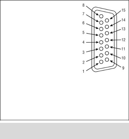
PIN FUNCTION
10 to 5 VDC Flow Signal Common
20 to 5 VDC Flow Signal Output
3Common
4Open (Purge)
5Common, Power Supply
6(unassigned)
7+12 VDC (+24 VDC*) Power Supply
8Remote Setpoint Input
94 to 20 mA (-) Flow Signal Return (use with 14)
10Remote Setpoint Common (use with 8)
11+5VDC Reference Output for Remote Setpoint
12Valve Off Control
13Auxiliary +12 VDC (+24 VDC*) Power Output (For Loads <100 mA)
144 to 20 mA (+) Flow Signal Output
15Chassis Ground
1 |
& 2 |
0-5 VDC OUTPUT |
|
5 |
& 7 |
+12 VDC (+24 VDC*) POWER SUPPLY |
3 |
& 4 |
PURGE |
|
8 |
& 10 |
0-5 VDC OR 4-20 mA REMOTE SETPOINT |
3 |
& 12 |
VALVE OFF CONTROL |
|
9 |
& 14 |
4-20 mA OUTPUT |
5 & 13 |
AUXILIARY +12 VDC (+24 VDC*) POWER |
|
10 & 11 |
+5 VDC CONTROL SOURCE |
||
|
|
OUTPUT (FOR LOADS <100 mA) |
|
|
|
|
FIGURE 2-1 FMA 5400/5500 15-PIN “D” CONNECTOR CONFIGURATION *+24 VDC power supply configuration is optional for only
FMA 5400/5500 Series Max. Flow 10, 50 and 100 L/min.
WARNING: DO NOT CONNECT 24Vdc POWER SUPPLY UNLESS YOUR FMA 5400/5500 CONTROLLER WAS ORDERED AND CONFIGURED FOR 24Vdc.
Important notes:
In general, “D” Connector numbering patterns are standardized. There are, however, some connectors with nonconforming patterns and the numbering sequence on your mating connector may or may not coincide with the numbering sequence shown in our pin configuration table above. It is imperative that you match the appropriate wires in accordance with the correct sequence regardless of the particular numbers displayed on your mating connector.
Power must be turned OFF when connecting or disconnecting any cables in the system.
The power input is protected by a 1600mA M (medium time-lag) resettable fuse. If a shorting condition or polarity reversal occurs, the fuse will cut power to the flow transducer circuit. Disconnect the power to the unit, remove the faulty condition, and reconnect the power. The fuse will reset once the faculty condition has been removed.
Use of the FMA 5400/5500 flow transducer in a manner other than that specified in this manual or in writing from OMEGA®, may impair the protection provided by the equipment.
3
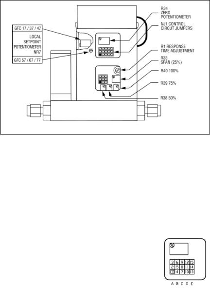
FIGURE 2-2, POTENTIOMETER AND JUMPER LOCATIONS
2.2.1Valve Control Configuration
There are three basic valve control options.
(a)LOCAL or REMOTE control.
(b)0 to 5 VDC or 4 to 20 mA setpoint signal -
*Note: this only applies for the REMOTE control configuration;
(c)2% cutoff active or not active. Note: 2% cutoff not available for FMA 200, 500 and
1000 L/min.
When active, the 2% cutoff will shut off the power to the valve when a setpoint of less than 2% of the full scale flow range is set. Figure 2-2 shows the jumper configurations for the three basic valve control options.
The factory default jumper settings are: LOCAL control, 2% cutoff off, and 0 to 5 VDC.
FUNCTION |
NJ1A |
NJ1B |
NJ1C |
NJ1D |
NJ1E |
|
|
|
|
|
|
0 to 5 VDC |
2 - 3 |
5 - 6 |
8 - 9 |
|
|
4 to 20 mA |
1 - 2 |
4 - 5 |
7 - 8 |
|
|
local |
|
|
|
11 - 12 |
|
remote |
|
|
|
10 - 11 |
|
2% cutoff on |
|
|
|
|
13 - 14 |
2% cutoff off |
|
|
|
|
14 - 15 |
|
|
|
|
|
|
FIGURE 2-3, VALVE CONTROL CONFIGURATION JUMPERS
2.2.2Remote LCD Readouts
FMA 5400/5500 Mass Flow Controllers are available with optional remote reading LCD displays supplied with a three foot long wire to accommodate most applications. This configuration includes the upper block element which serves as the LCD readout mounting. Special lengths of remote extension wiring (up to 9.5 feet [3 meters] are available on request.
4
2.2.3Panel Mounting Readouts
Another option for the FMA 5400/5500 Mass Flow Controller is the Panel Mounting Remote Readout.
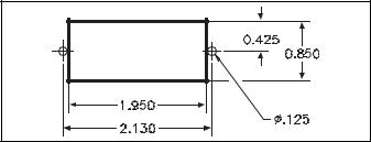
In this configuration the LCD readout is supplied with a three foot long extension wire, and no aluminum housing around the LCD. The LCD readout for panel mounting includes a bezel with two plastic screws which conveniently fit into a rectangular cut-out for panel mounting (see Figure 2-3).
FIGURE 2-3 CUTOUT DIMENSIONS FOR LCD PANEL MOUNTING
3.PRINCIPLE OF OPERATION
The stream of gas entering the Mass Flow transducer is split by shunting a small portion of the flow through a capillary stainless steel sensor tube. The remainder of the gas flows through the primary flow conduit. The geometry of the primary conduit and the sensor tube are designed to ensure laminar flow in each branch. According to principles of fluid dynamics flow rates of gas in two properly sized laminar flow conduits are related to one another. Therefore, the flow rates measured in the sensor tube are directly proportional to the total flow through the transducer.
In order to sense the flow in the sensor tube, heat flux is introduced at two sections of the sensor tube by means of precision wound heater-sensor coils. Heat is transferred through the thin wall of the sensor tube to the gas flowing inside. As gas flow takes place heat is carried by the gas stream from the upstream coil to the downstream coil windings. The resultant temperature dependent resistance differential is detected electronically. The measured gradient at the sensor windings is linearly proportional to the instantaneous rate of flow taking place.
An output signal is generated that is a function of the amount of heat carried by the gases to indicate mass-molecular based flow rates.
FMA 5400/5500 Mass Flow Controller Series Max. Flow 10, 50 and 100 L/min also incorporate a proportionating solenoid valve and Series Max. Flow 200, 500 and 1000 L/min a motorized valve. The closed loop control circuit of the FMA 5400/5500 continuously compares the mass flow output with the selected flow rate. Deviations from the setpoint are corrected by compensating valve adjustments, thus maintaining the desired flow parameters.
5
4.SPECIFICATIONS
FLOW MEDIUM: Please note that FMA 5400/5500 Mass Flow Controllers are designed to work with clean gases only. Never try to meter or control flow rates of liquids.
CALIBRATIONS: Supplied at Standard Conditions (14.7 psia and 70F F), or Normal Conditions (0 FC and 1.01 bar abs) unless otherwise requested or stated.
ENVIRONMENTAL (per IEC 664): Installation Level II; Pollution Degree II.
ACCURACY:
|
ACCURACY %FS |
|
OPTIONAL ENHANCED ACCURACY %FS |
|||||
|
FMA 5400 |
FMA 5400/5500 |
|
FMA 5400 |
FMA 5400/5500 |
|||
MODEL: |
/5500 15, 50 |
100, 200, 500, |
MODEL: |
/5500 15 |
50, 100, 200, 500, |
|||
|
L/min |
1000 L/min |
|
L/min |
1000 L/min |
|
||
FLOW |
2.5-100% |
20-100% |
0-20% |
FLOW |
2.5-100% |
20-100% |
0-20% |
|
RANGE: |
RANGE: |
|||||||
|
|
|
|
|
|
|
|
|
ACCURACY: |
±1.5% |
±1.5% |
±3% |
ACCURACY: |
±1% |
±1% |
|
REF DATA |
|
with ±1% |
|||||||
|
|
|
|
|
|
|
|
|
|
|
|
|
|
|
|
|
|
REPEATABILITY: ±0.5% of full scale.
TEMPERATURE COEFFICIENT: 0.15% of full scale/ FC.
PRESSURE COEFFICIENT: 0.01% of full scale/psi (0.07 bar).
RESPONSE TIME: FMA 5400/5500 Series Max. Flow 10 L/min: 300ms time constant; approximately 1 second to within ±2% of set flow rate for 25% to 100% of full scale flow.
FMA 5400/5500 Series Max. Flow 50 & 100 L/min: 600ms time constant; approximately 2 seconds to within ±2% of set flow rate for 25% to 100% of full scale flow.
FMA 5400/5500 Series Max. Flow 200, 500 & 1000 L/min: 1800ms time constant; approximately 5 seconds to within ± 2% of set flow rate for 25% to 100% of full scale flow.
MAX GAS PRESSURE: 1000 psig (69 bars) 10, 50 and 100 L/min; 500 psig (34.5 bars) optimum pressure is 20 psig (1.4 bars).
TURNDOWN RATIO: 40:1.
MAX DIFFERENTIAL PRESSURE: 50 psid (345 kPa).
GAS TEMPERATURE: 32 FF to 122 FF (0 FC to 50 FC).
AMBIENT TEMPERATURE: 14 FF to 122 FF (-10 FC to 50 FC).
6
GAS RELATIVE HUMIDITY: Up to 70%.
MAXIMUM INTERNAL LEAK: 0.5% FS.
LEAK INTEGRITY: 1 x 10⁻⁷ sccs He max to the outside environment.
ATTITUDE SENSITIVITY: No greater than ±15 degree rotation from horizontal to vertical; standard calibration is in horizontal position.
OUTPUT SIGNALS: Linear 0 to 5 VDC (1000 Ω minimum load impedance) and 4 to 20 mA (0 to 500 Ω loop resistance); 20 mV peak to peak max noise for FMA 10, 50 and 100 L/min and 100 mV peak to peak max noise for FMA 200, 500 and 1000 L/min.
COMMAND SIGNAL: Analog 0 to 5 VDC (100 KΩ input impedance) or 4 to 20 mA (0 to 250 Ω input impedance).
Contact OMEGA® for optional RS232 or IEEE488 interfaces.
TRANSDUCER INPUT POWER: +12 VDC, 800 mA maximum; FMA Series Max. Flow 10, 50 and 100 L/min have an OPTION of +24 VDC, 650 mA maximum - IF SPECIFIED AT
TIME OF ORDERING AND CONFIGURED ACCORDINGLY. WETTED MATERIALS:
FMA 5400/5500 Series Max. Flow 10, 50, 100, 200, 500 and 1000 L/min:
Anodized aluminum, brass, 416 Stainless Steel and 316 stainless steel with FKM O-rings seals; BUNA, EPR or Perflouroelastomer O-rings are optional.
FMA 5400ST/5500ST Series Max. Flow 10, 50, 100, 200, 500 and 1000 L/min:
416 Stainless Steel and 316 stainless steel with FKM O-rings seals; BUNA, EPR or Perflouroelastomer O-rings are optional.
OMEGA® makes no expressed or implied guarantees of corrosion resistance of mass flow meters as pertains to different flow media reacting with components of meters. It is the customers sole responsibility to select the model suitable for a particular gas based on the fluid contacting (wetted) materials offered in the different models.
INLET AND OUTLET CONNECTIONS: |
|
FMA Series Max. Flow 10 and 50 L/min: |
1/4" compression fittings. |
Optional: 6mm compression, 1/4" VCR ®, 3/8" or 1/8" compression fittings. |
|
FMA Series Max. Flow 100 and 200 L/min: |
3/8"compression fittings. |
FMA Series Max. Flow 500 L/min: |
1/2" compression fittings. |
FMA Series Max. Flow 1000 L/min: |
3/4" FNPT ports. |
Optional: 3/4" compression fittings. |
|
LCD DISPLAY: 3½ digit LCD (maximum viewable digits “1999”, 0.5 inch high characters. On FMA 5400/5500 aluminum or stainless steel models the LCD display is built into the upper block element and may be tilted over 90 degrees for optimal viewing comfort. Remote or panel mounting remote reading is optional.
7
Standard readings are in direct engineering units for the given gas and flow rate (i.e. liters/minute [slpm], standard cubic centimeters/minute [sccm], standard cubic
feet/hour [scfh], etc.). 0 to 100% LCD calibration scaling is available upon request at time of order. Contact OMEGA® when non-standard display settings are desired.
TRANSDUCER INTERFACE CABLE: Optional shielded cable is available mating to the FMA 5400/5500 transducer 15-pin “D” connector.
4.1CE Compliance
FMA 5400/5500 Mass Flow Controllers are in compliance with CE test standards stated below:
EMC Compliance with 89/336/EEC as amended; Emission Standard: EN 55011:1991, Group 1, Class B Immunity Standard: EN 55082-1:1992.
4.2Flow Capacities
Table I
Low Flow
Mass Flow Controller*
CODE |
mL/min [N2] |
CODE |
liters/min [N2] |
||
02 |
0 to |
10 |
14 |
0 to |
1 |
|
|
|
|
|
|
04 |
0 to |
20 |
16 |
0 to |
2 |
|
|
|
|
|
|
06 |
0 to |
50 |
18 |
0 to |
5 |
|
|
|
|
||
08 |
0 to 100 |
20 |
0 to 10 |
||
10 |
0 to 200 |
|
|
|
|
|
|
|
|
|
|
12 |
0 to 500 |
|
|
|
|
|
|
|
|
|
|
Table II
Medium Flow
Mass Flow Controller*
CODE |
liters/min [N2] |
23 |
15 |
24 |
20 |
26 |
30 |
27 |
40 |
28 |
50 |
Table III
High Flow
Mass Flow Controller*
CODE |
liters/min [N2] |
40 |
60 |
41 |
80 |
42 |
100 |
43 |
200 |
44 |
500 |
45 |
1000 |
*Flow rates are stated for Nitrogen at STP conditions [i.e. 70 FF (21.1 FC) at 1 atm]. For other gases use the K factor as a multiplier from APPENDIX 2.
8
 Loading...