


CL3515R K/J/T/E/R/S/N/L/U/B/C Calibrator Thermometer
GENERAL SPECIFICATIONS
Displays:
There are three different display areas, Main Second and Third. The Main and Second display panels are 4 1/2 digit liquid crystal display (LCD) with maximum reading of 19999. The main is used for displaying the value of T1, T2 or output setting. The second displays T1 or T2 readings and the third T1-T2 and groups settings.
Battery:
Standard 9V battery (NEDA 1604, IEC 6F22 006P). Battery life is about 17.5 hours when used with a carbon zinc battery.
Low battery indication:
The " " is displayed when the battery voltage drops below the operating level. Dimensions: 192mm(H) x 91mm(W) x 52.5mm(D).
Weight: 320g.
EMC:
Through the RS radiation interference test the frequency of 80MHz to1000MHz, the measurement number producing the unsteady flutter, it immediately recover after stop the test.
Accessories:
Two type “K” thermocouple bead wires. Two type “K” thermocouple calibration bead wires. Maximum insulation temperature 260°C (500°F). Wire accuracy ±2.2°C or ±0.75% of reading (whichever is greater) from 0°C to 800°C.
A 9 volts battery.
An instruction manual. Pc connection software. Pc interface cable.
ENVIRONMENTAL
Ambient Operating Ranges:
0°C to 50°C (32°F to 122°F) <80% R.H.
Storage Temperature:
-20°C to 60°C (-4°F to 140°F) <70% R.H.
Input Connector:
Accepts standard miniature thermocouple connectors (flat blades spaced 7.9mm, center to center).
CL3515R K/J/T/E/R/S/N/L/U/B/C Calibrator Thermometer
Type
K, J, T, E, R, S, N, L, U, B, C, mV
Step Item
Step 1 to Step 10
Edit
Default
CL3515R setting values.
Clear
Clear the current group.
Clear All
Clear all group’s value.
7.File Load
From PC load the stored value.
Save
Save the setting value into PC. Setup
2 |
15 |

CL3515R K/J/T/E/R/S/N/L/U/B/C Calibrator Thermometer
THERMOCOUPLE SIMULATE RANGE
Resolution: 0.1° (1° for R/S/B/C-TYPE) Accuracy: ±(0.3°C + 10uV)
Accuracy: Specified for operating temperatures over the range of 18°C to 28°C (64°F to 82°F), for 1 year, not including thermocouple error.
mV Range:
Range: -25.00mV to 75.00mV Resolution: 10uV
Accuracy: ±(0.025% + 1 digit)
Temperature Coefficient:
0.1 times the applicable accuracy specification per °C from 0°C to 18 and 28°C to 50°C (32°F to 64°F and 82°F to
122°F). |
3 |
4 |
|
Top Side: |
|
|
|
1. |
Output 1. |
1 |
2 |
2. |
Output 2. |
||
3. |
Input T1. |
|
5 |
4. |
Input T2. |
|
|
5. |
RS232 optical interface. |
|
|
OPERATING INSTRUCTIONS
CL3515R
4
CL3515R K/J/T/E/R/S/N/L/U/B/C Calibrator Thermometer
4. Record
Export
Both
Display drawing T1 and T2.
T1
Display drawing T1.
T2
Display drawing T2.
State Value
Setting Interval.
Start
Log
File type *.txt or *.xls
Quit
Exit
13
CL3515R K/J/T/E/R/S/N/L/U/B/C Calibrator Thermometer
7.“T1/T2 SOURCE” button
Pressing T1/T2 SOURCE to cycle through T1, T2 and SOURCE. In the main display
the blinking digit is the one to be adjusted, you can push the “ ” button to make right or left shifts to the desired position. When incrementing to the utmost range of the selected thermocouples, the LIMIT will show on the display.
SOURCE is to provide the output parameter settings. There are ten individual temperature setting points in group 0, which can be set at your desired output point. Use “ ” to shift the desired digit to be adjusted and rotate the knob to increase or decrease the values you want to set. Press the T/C OFFSET to save the settings.
8.“OFFSET” button (Thermocouple offset adjust)
When the main display input is T1 or T2, and socket thermocouple is connected. Press T/C OFFSET over two seconds the SET annouciator will appear on the right side of display and enter the offset adjustment mode. And the blinking digit is the one to be adjusted. Rotate the knob to the right increasing the values, to the left side decreasing the values. The maximum range of the knob is ±5 centigrade. When turning to the utmost range, it will appear LIMIT symbol on the left side of the display and means that there is no further incrementing of the offset. Press the T/C OFFSET over two seconds to save the settings.
9.“MIN/MAX” button
Press MIN/MAX button to enter the MIN/MAX recording mode and REC shows on the display. The beeper emits a tone when a new minimum or maximum measurement is recorded. Press the MIN/MAX button again to rotate through the current readings: MAX: The highest measurement recorded.
MIN: The lowest measurement recorded.
MAX-MIN: The difference of the highest and the lowest measurement. AVG: The average values of the measurements.
Press MIN/MAX button over two seconds to exit the function.
10.Knob usages in the settings
In the TYPE mode, it is used for thermocouples selection to make right or left shifts to choose selectors. In the SOURCE mode, it is used to increase or decrease the values of the output function.
11.PWM Group
Group 0 set
In the OUT mode, press T/C OFFSET over two seconds to set.
LCD display Set CLEAr press T1/T2 SOURCE button to clear data, display SEt 0-0. In the main display the blinking digit is the one to be adjusted, you can push the
“ ” button to make right or left shifts to the desired position. Rotary knob to increase or decrease the values. Press T1/T2 SOURCE to save the one step setting. CL3515R can set 10 step, (Group 1 to 9 use software setting) press T/C OFFSET exit group set mode.
6
CL3515R K/J/T/E/R/S/N/L/U/B/C Calibrator Thermometer
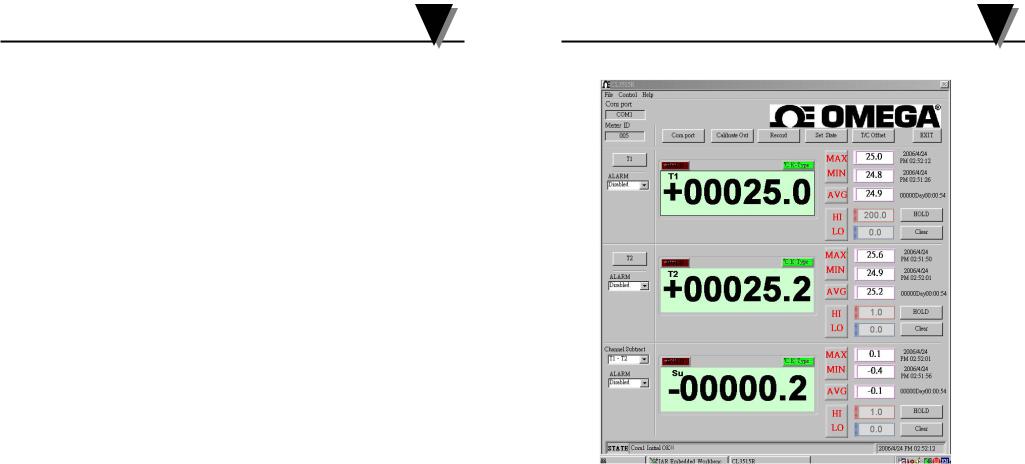
IV Measurement
1.T1, T2, Channel Subtract (NONE, T1-T2, T2-T1) ALARM function
Disable Hi enable
Enables alarm Hi function, and it will become red flashing, when it is over Hi setting value.
Lo enable
Enables alarm Lo function, and it will become blue flashing, when it is below Lo setting value.
Both enable
To enable both Hi and Lo, and it will become red flashing, when it is over Hi setting value, and it will become blue flashing when it is below Lo setting value.
HOLD
Hold the present reading.
Clear
Clear MAX, MIN, AVG recorded.
11
 Loading...