

Page 1
OTEB-CO-B EDFA WITHOUT SNMP
INSTRUCTION MANUAL
E-Mail: salessupport@olsontech.com
OTEB-CO-B (No SNMP) Rev. X7
Phone: (209) 586-1022
(800) 545-1022
Fax: (209) 586-1026
www.olsontech.com
11/17/2010
Page 2

SAFETY WARNINGS
LASER RADIATION
The OTEA-CO-B EDFA emits invisible radiation that can cause permanent eye damage.
DIRECT EXPOSURE TO BEAM.
the optical connector. Power to the OTEA-CO-B EDFA should be turned off or preferably,
disconnected whenever the optical connector cover is opened and there is no installed fiber (as
when the fiber connector is being installed or removed from the optical connector). When the
amplifier isworking in normal state, theoutput power of lightwith wavelengths in theinvisible range
(
infrared light) may exceed +26dBm (400mW). Therefore, to avoid damaging your eyes, do not
look into the outputport oftheEDFAdirectly.
NEVER
look at the end of the fiber to see if light is coming out Most fiber optic laser
wavelengths (1310nm and 1550nm) are totally invisible to the unaided eye and will cause
permanent damage.Always useinstruments, such asanoptical power meter,to verify lightoutput.
Use extreme carewith ,
NEVER
look intothe output ofthe EDFA or afiber connected toan EDFA
NEVER
clean an optical connectorwith opticalpowerpresent.
NEVER
look into or use any optical instrument to view the distant end of a fiber that may be
connected directly or via an optical splitter, to a transmitter or EDFA that may be operating. This
specifically applies to fibers that are to be connected to receivers (such as the OTPN-2000C) or
other devices at anydistance fromthelasertransmitter or EDFA.
ALWAYS
read the product data sheet and the laser safety label before powering the product
Note theoperation wavelength, optical outputpower and safetyclassifications. If safetygoggles or
other eye protection are used, becertain that the protection is effective at the wavelength emitted
by the device undertest applying power.
ALWAYS
connect a fiber to the output of the device power is applied. Power should
never be appliedwithout an attached fiber.Ifthe device has aconnector output, a connector should
be attached that is connected to a fiber. This will ensure that all light is confined within the fiber
waveguide, virtually eliminating allpotential hazard.
The OTEA-CO-B EDFA contains no user serviceable parts. There is exposed high voltage inside
this unit. Only authorizedfactory servicetechniciansshouldopen the unit with power applied.
The OTEA-CO-B EDFA is designed for indoor use only. Direct exposure to moisture must be
avoided. Ifyouhavequestions about laser safety procedures,please call Olson Technology before
powering your product. The fiber amplifier is sensitive equipment. Do not open the case of the
amplifier to avoid damaging the internal component devices. Opening the case of the amplifier
without the written permissionof OlsonTechnology,Inc., will void the warranty.
Operate the EDFAonly with the proper optical fiber installed in
NEVER
.
magnifying glasses microscopes,etc.
BEFORE
BEFORE
HIGH VOLTAGE
SHOCK HAZARD
.
!
AVOID
.
Page 3
INTRODUCTION
Olson Technology, Inc. provides a wide range of Erbium Doped Fiber Amplifiers
(EDFA’s), for 1550nm HFC networks that feature low noise figure, stable output power
and excellentenvironmental stability. EDFA’s are comprised of two main parts:the gain
module andthe externalcontrol system.The gainmodule amplifies the optical signal in
1550nm wavelength band (1540-1560nm typically). It is made of high quality optical
components, and carefully designed to maximize overall performance. Low power
'
EDFA s may only have a single pump, while high power units can have up to three
pumps. Theexternal control system allows the operator toensure that the gain module
is working optimally Controlled by microprocessor it monitors the states of the gain
module and adjusts all the parameters to ensure a stabilized output power of the gain
module. This system also provides warnings via the front panel indicator LED and a
digital display The LCD on the front panel shows the detailed working parameters of
the EDFA This information can also be accessed via the standard RS 232 interface
via an externalcomputer.
.-
.,
.
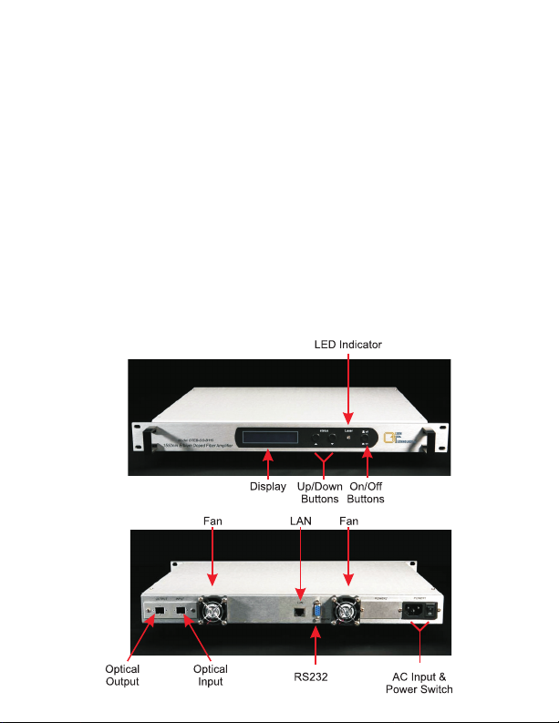
OPERATION PANEL DESCRIPTION
Page 4

STATUS DISPLAY PANEL OPERATION
The microprocessor software monitors the function of a numberof systemparameters.
Press the ▼and▲buttons to displaykey working parameters sequentially.
Optical Input Power
- Input power: INPUT = display input power (dBm)
• Input power = +10dBm = >alarm
• Input power = -10dBm => display NO INPUT =>shut down the power supply of
the laser.
• Input power = 0dBm => reach fixed output power.
Optical Output Power
- Output: OUTPUT = display output power (dBm)
• Tolerance = ±0.2dBm
• No input = power supply of the laser will be shut down automatically => display
NO INPUT => NO OUTPUT
Laser Temperature
- Laser temperature: TEMP = laser temp is set to operate in the
range of 20-30°C
• if exceeded => LCD will display “READY” => red LED indicator will light, and the
power supply of the laser will shut down automatically.
Laser Bias
- Bias: BIAS = Bias is the key index of the laser, if it exceeds the fixed
range power supply of the laser, the power supply will be shut down automatically to
protect the laser.
Laser Heating/Cooling
- Cooling/heating: COOLING/HEATING = standard
temperature for laser 25°C
- Thermoelectric cooler 25°C
TEC
• At high ambient temperatures, the LCD will display => COOLING
• At low ambient temperatures, the LCD will display =>HEATING
Voltage
+5V Voltage: +5V READS… => ±0.5V alarm
-5V Voltage: -5V READS… => ±0.5V alarm
Serial Number
IP Address for RS-232 Connector
- Displays the serial number of the EDFA.
- The IP address code can be set by the
operator via the RS-232 connector on the rear panel.
Page 5

DESCRIPTION OF STATUS ALARM
The front panelindicatorLED indicator maybered, green, oroff. Whenthe LED isgreen
the EDFA is operating properly. Whenthe LED is off, the unit is off. A red LED indicates
an alarm condition.The alarmcondition will be displayedon thedisplay panel.
With proper power supply, if the EDFAis functioning normally and the LED indicator is
red, the digital panel will display “READY KEY OFF. Turn on with the key. The display
shows KEY OFF for10 seconds,then the LEDindicator changesto green.
Pressing the STATUSbutton displays the followingparameters:
• Input power -10 dBm, display => NO INPUT; the EDFA cannot be turned on and
<
the LED isred.
• If any faultlisted above hasoccurred, there willbean alarm. Themicroprocessor will
shut down the laser automatically, and the digital panel will display the cause of the
fault.
• In order to protect the laser, there is a time-delay function. After turning the laser on
with the key, thelaserwillstart to workafter 10seconds.
NOTES ON OPERATION
The EDFAshould have good grounding and grounding resistance to 4 . According to
Ω
the international standard, on an AC three-wire plug, the middle wire is the grounding
wire.
The EDFAincorporatesa high performance, highreliability, switching powersupply with
over-voltage protection. Themicroprocessor monitors theoutputDC voltage. Ifthe fuse
blows, the unitshould bereturned to Olson forservice.
In order to keep the reflection loss to <-55dB, the EDFA uses SC/APC optical
connectors. Other connector types, such as FC/PC, cannot be used with the EDFA.
Keep the connectorclean wheninstalling the opticalcables. Clean itwith lint-free tissue
with anhydrous alcohol after several rounds of connection/disconnection from the unit.
NEVER clean theoptical connectorswith the unit powered!
Page 6

Input
Optical
Splitter
Optical
Isolator
EDFA BLOCK DIAGRAM
Erbium-Doped Fiber
WDM
1550/980
1550/980-1490
WDM
Optical
Isolator
Optical
Splitter
Output
3.5
3.0
2.5
2.0
1.5
1.0
0.5
0.0
Input
Power
Detector
PD
Thermoelectric Cooler
Front Panel
Status Monitor
RS-232
Pump Laser
980nm
Average Power Control
Micro-Processor
CPU Control Unit
Pump Laser
980/1480nm
Thermoelectric Cooler
Status Alarm
Display
LCD/VFD
Typical Catv CNR Degradation
0
1234 5678910
EDFA Optical Input (dBm)
PD
Output
Power
Detector
Page 7

MODELS AND OUTPUTS
Typical Models
# of Outputs
Output Power (dBm)
115
15
116
117
118
119
120
1
1
16
17
1
18
19
1
20
1
SPECIFICATIONS
Optical Characteristics (with SM 9/125µm Fiber)
Min Typ Max Units
Operating Wavelength 1540 1560 nm
Input Power Range -10 +10 dBm
Max. Alarm 10 dBm
Min. Alarm -10 dBm
Output Stability -0.3 +0.3 dB
Noise Figure (0dBm In) 4.5 5.0 5.3 dB
Noise Figure (6dBm In) 5.5 6.0 6.5 dB
<<<
<<<
Polarization 0.2 dB
PMD 0.5 ps
Reflection Loss 40 dB
Optical Connector SC/APC
Network Interface RS-232/RJ45
Electrical & Environmental Characteristics
Min Typ Max Units
Operating Temp. Range +5 +45 °C
Storage Temp. Range 0 +55 °C
Relative Humidity 10 90 %
1
P. S. Voltage +85 +264 V
P. S. Voltage -48 V
Power Consumption 50 W
121
122
1
1
21
22
NOTES:
1) Non-condensing.
AC
DC
123
124
221
419
1
1
23
1
24
21
4
2
19
Page 8

[BLANK PAGE]
 Loading...