

Page 1
BCL-S BFL
(Lowboy Model)
BCL
(High Capacity Lowboy Model)
Oil Fired Warm Air Furnaces
INSTALLATION, OPERATION &
MAINTENANCE MANUAL
An ISO 9001-2008 Certified Company
ECR International
2210 Dwyer Avenue, Utica NY 13501
web site: www.ecrinternational.com
P/N# 28141, Rev. H [03/2014]
Page 2
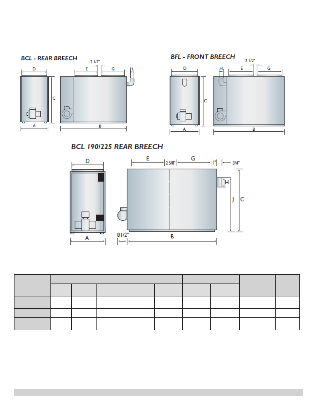
Dimensions
Furnace
Model
BCL-S 22 51½ 41 20½ x 18⅝ 20½ x 18⅝ 6 37¼ 20 x 25 x 1 280
BFL
BCL
High Capacity
WidthALengthBHeight
22
26 49 56 24 x 22 24 X 22 7 47
Cabinet Plenum Openings Flue
C
51½ 41 20½ x 18⅝ 20½ x 18⅝
Supply
D x E
Return
F x G
DiameterHHeight
6
Filter
(Permanent)
J
38¼ 20 x 25 x 1
20 x 25 x 1
(2)
2
Shipping
Weight
(LB)
250
390
Page 3

Contents
Dimensions ................................................................................................................................. 2
1. General .................................................................................................................................. 4
2. Safety Symbols ....................................................................................................................... 4
3. Introduction ............................................................................................................................ 4
4. Heat Loss ............................................................................................................................... 4
5. Locating the Unit - [See Table 1] ................................................................................................ 5
6. Furnace Used In Conjunction With Air Conditioning ....................................................................... 5
7. Combustion Air ........................................................................................................................ 6
8. Chimney Venting ..................................................................................................................... 6
9. Barometric Damper Control ...................................................................................................... 7
10. Optional Side Wall Venting ...................................................................................................... 7
11a. Models with Electronic Fan Timer control and Snap-Disc Limit Control (See Figure 3) .................... 7
11b. Models with Mechanical Fan And Limit Control ......................................................................... 8
12. Electrical Connections ............................................................................................................ 8
13. Humidier ............................................................................................................................ 9
14. Piping Installation ................................................................................................................. 9
15. Oil Filter .............................................................................................................................. 9
16. Oil Burner Nozzles ................................................................................................................. 9
17. Oil Burner Adjustment ........................................................................................................... 9
18. Burner Electrodes.................................................................................................................. 9
19. Burner Primary (Safety) Control .............................................................................................. 9
20. Combustion Chamber ............................................................................................................ 9
21. Circulating Air Blower ...........................................................................................................10
22. Maintenance And Service ......................................................................................................11
23. Operating Instructions ..........................................................................................................12
Appendix A - Check Out and Adjustments ............................................................................... 13
A.1 Oil Burner Air Adjustment ...................................................................................................14
A.2 Burner Electrodes ..............................................................................................................15
A.3 Start Up ...........................................................................................................................15
A.4 Special Instructions For Units Equipped With Riello Burners .....................................................16
A.5 Final Check Out ................................................................................................................16
Blower Setup Tables ................................................................................................................ 17
Airow Characteristics Tables ................................................................................................. 19
Appendix B - Wiring Diagrams ................................................................................................. 21
Chimney Vent Direct Drive Furnace Wiring Diagram BCL-S & BFL With Fan and Limit Control .............21
Chimney Vent Belt Drive Furnace Wiring Diagram BCL-S & BFL & BCL High Capacity with Fan and Limit Control .......22
Direct Vent Direct Drive Furnace Wiring Diagram BCL-S & BFL with Fan and Limit Control .................23
Chimney Vent Furnace Wiring Diagram BCL-S & BFL with Fan Timer Control ....................................24
Direct Vent Furnace Wiring Diagram BCL-S & BFL with Fan Timer Control .......................................25
Appendix C - Sequence of Operation and Troubleshooting ...................................................... 26
C.1 Troubleshooting ................................................................................................................27
C.2 Preliminary Steps: .............................................................................................................27
C.3 Check Oil Primary Control ...................................................................................................27
Parts Listing ............................................................................................................................ 31
Model BCL High Capacity Diagram .............................................................................................31
Model BCL-S Diagram (Fan and Limit Control Shown) ...................................................................34
Model BFL Diagram (Fan and Limit Control Shown) ......................................................................39
Home Owners Reference Table ................................................................................................ 44
Check our website frequently for updates: www.ecrinternational.com
Information and specications outlined in this manual in effect at the
time of printing of this manual. Manufacturer reserves the right to
discontinue, change specications or system design at any time without
notice and without incurring any obligation, whatsoever.
3
Page 4
1. General
Furnace installation shall be completed by qualied agency.
See glossary for additional information.
WARNING
!
Fire, explosion, asphyxiation and electrical shock
hazard. Improper installation could result in death
or serious injury. Read this manual and understand
all requirements before beginning installation.
WARNING
!
Fire, burn, asphyxiation hazard. Do not use
gasoline, crank case oil, or any oil containing
gasoline. Failure to follow these instructions could
result in death or serious injury.
2. Safety Symbols
Become familiar with symbols identifying
potential hazards.
This is the safety alert symbol. Symbol alerts you to
potential personal injury hazards. Obey all safety messages
following this symbol to avoid possible injury or death.
3. Introduction
• Models BCL (90, 100, 120, 130, 145) S
BCL-S models are rear breech oil red forced air lowboy
furnaces with output capacity range of 90,000 to 141,000
Btu/hr.
• Models BFL (90, 100, 120, 130, 145)
BFL models are front breech oil red forced air lowboy
furnaces with output capacity range of 88,000 to 139,000
Btu/hr.
• Models BCL (170-2, 190, 200, 225)
BCL models are rear breech high capacity oil red
forced air lowboy furnaces with output capacity
range of 177,000 to 237,000 Btu/hr. Shipped in two
pieces; furnace section and blower section, which are
assembled together at the installation site.
Furnace models are either factory equipped for chimney
venting or factory equipped for direct venting.
Chimney vent models and direct vent models are not
eld convertible. Direct vent installation instructions are
included with the direct vent models.
Installation shall conform to requirements of
authority having jurisdiction or in absence of such
requirements:
• Canada - CAN/CSA - B139, Installation Code for OilBurning Equipment.
!
DANGER
Indicates a hazardous situation which, if not avoided,
WILL result in death or serious injury
!
WARNING
Indicates a hazardous situation which, if not avoided,
could result in death or serious injury.
!
CAUTION
Indicates a hazardous situation which, if not avoided,
could result in minor or moderate injury.
NOTICE
Used to address practices not related to personal
injury.
• United States - National Electrical Code, NFPA31,
Standard for the Installation of Oil-Burning Equipment.
Models are CSA listed, (NRTL/C) for use with No. 1
(Stove) and No. 2 (Furnace) Oil.
Refer to tables in Appendix A for performance data.
4. Heat Loss
Maximum hourly heat loss for each heated space shall be
calculated in accordance with the procedures described in
the manuals of:
• Canada - The Heating, Refrigeration and Air
Conditioning Institute of Canada (HRAI), or by other
means prescribed, or approved by the local authority
having jurisdiction.
• United States - Manual J. titled, "Load Calculation"
published by the Air Conditioning Contractors of
America, describes a suitable procedure for calculating
maximum hourly heat loss.
4
Page 5

5. Locating the Unit - [See Table 1]
• Locate furnace so ue connection to chimney is short,
direct and consists of as few elbows as possible.
• Centralize furnace location with respect to supply and
return air ductwork. Central location minimizes trunk
duct sizing.
• All models may be installed on combustible oors.
6. Furnace Used In Conjunction With Air
Conditioning
• Install furnace in parallel with or upstream from
evaporator coil to avoid condensation in heat
exchanger.
• When installed in parallel, prevent chilled air from
entering furnace by use of dampers or air controlling.
• Manually operated dampers must have a control to
prevent operation of either system unless dampers
are in full heat or full cool position.
• Air heated by the furnace shall not pass through
evaporator coil unless coil is specically approved for
such service.
Table 1: Minimum Installation Clearances
Location
Top 1 3
Bottom 0 0
S/A Plenum 1 3
Rear 6* 24
Side 1 6* 6***
Side 2 24 18
Front 24 24
Flue Pipe 9** 9**
Enclosure Standard Standard
* 24 Required Service Clearance
** 18 in USA
*** Required on one side only for service to rear
Clearance to Combustibles (Inches)
BCL-S and BFL BCL High Capacity
• Check and adjust blower speed to compensate for
pressure drop caused by evaporator coil.
5
Page 6
7. Combustion Air
• Furnace installed in a closet or utility room, provide
two openings connecting to well-ventilated space (full
basement, living room or other room opening, not a
bedroom or bathroom).
A. One opening shall be located above level of upper
vent opening.
B. One opening below combustion air inlet opening
in front of furnace.
Each opening shall have a minimum free area of 1½
square inches per 1,000 Btu/h of total input rating of
all appliances installed in the room.
• For furnaces located in buildings of unusually tight
construction, such as those with high quality weather
stripping, caulking, windows and doors, or storm
sashed windows, or where basement windows are
well sealed, a permanent opening communicating
with a well ventilated attic or with the outdoors shall
be provided, using a duct if necessary. The duct
opening shall have a free area of 1½ square inches
per 1,000 Btu/h of total input rating of all appliances
to be installed.
WARNING
!
Asphyxiation hazard. Chimney vented versions of furnace
must be connected to ue having sufcient draft at all
times. Failure to follow these instructions could result in
death or serious injury.
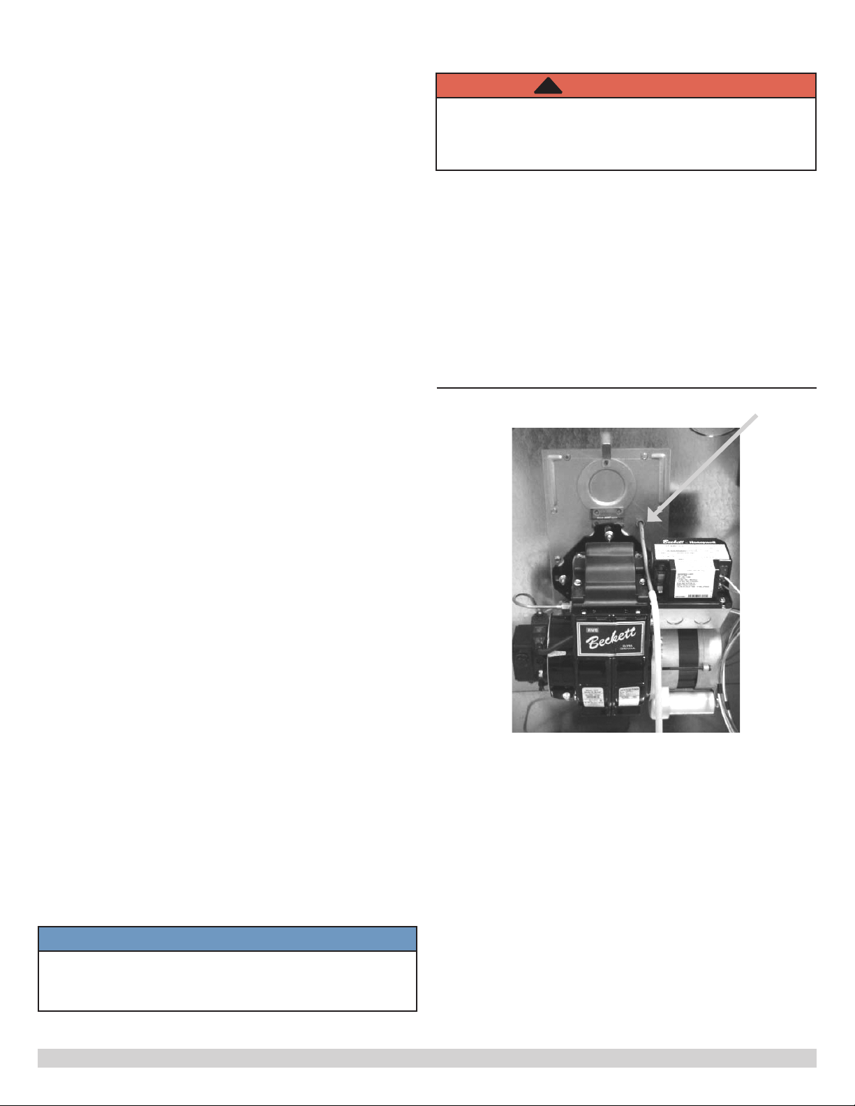
Manufacturer recommends over re draft of -0.02 in. w.c.
See Figure 2.
Flue pipe must not pass through any oor or ceiling,
may pass through a wall where suitable re protection
provisions have been installed.
• Refer to CAN/CSA B-139 for rules governing the
installation of oil burning equipment.
• United States, refer to NFPA 31 for regulations
governing the installation of oil burning equipment.
See Appendix A for burner set-up.
Figure 2 - Check Over-Fire Draft
• Furnace installed in a full basement, inltration is
normally adequate to provide air for combustion and
draft operation.
• Furnace rooms under 65m³ (700 ft³) should
automatically be treated as conned space.
8. Chimney Venting
• Flue pipe should be as short as possible with
horizontal pipes sloping upward toward the chimney
at a rate of one-quarter inch per foot.
• Flue pipe should not be smaller in cross sectional
area than ue collar on the furnace.
• Flue pipe should connect to chimney so the ue pipe
extends into, and terminates ush with the inside
surface of chimney liner. Seal the joint between pipe
and lining.
• Chimney outlet should be at least two feet above
highest point of peaked roof.
• All unused chimney openings should be closed.
• Chimneys must conform to local, provincial or state
codes, or in the absence of local regulations, to the
requirements of the National Building Code.
Over-re draft access port.
NOTICE
This furnace is approved for use with Type L vent or
equivalent. Maximum vent temperature for Type L
vent is 575°F (300°C).
6
Page 7
9. Barometric Damper Control
Barometric damper control, also known as draft regulator,
is used on conventional chimney venting only. Control
automatically maintains constant negative pressure.
Ensures proper pressures are not exceeded. If chimney
does not develop sufcient draft, draft control does not
function properly.
• Install draft regulator in same room or enclosure as
furnace. Draft regulator should not interfere with
combustion air supplied to the burner.
• Locate control near furnace ue outlet.
• Install per instructions supplied with regulator.
• Set over re draft, measured at oil burner mounting
plate over-re draft access port, to -0.02 in. w.c. See
Figure 2 page 6.
10. Optional Side Wall Venting
Certain BCL-S and BFL furnace models are manufactured
as sidewall vented units. Refer to Direct Venting Instructions,
P/N 240006979 included with Vent Kit for details.
Sidewall Venting (Direct Venting) requires use of specic oil
burners; Beckett AFII.
Refer to Appendix A, Table A2.
11a. Models with Electronic Fan Timer Control
and Snap-Disc Limit Control (See Figure 3)
Electronic Fan Timer integrates control of burner and
circulator fan operations. Control is central wiring point for
most of furnace electrical components.
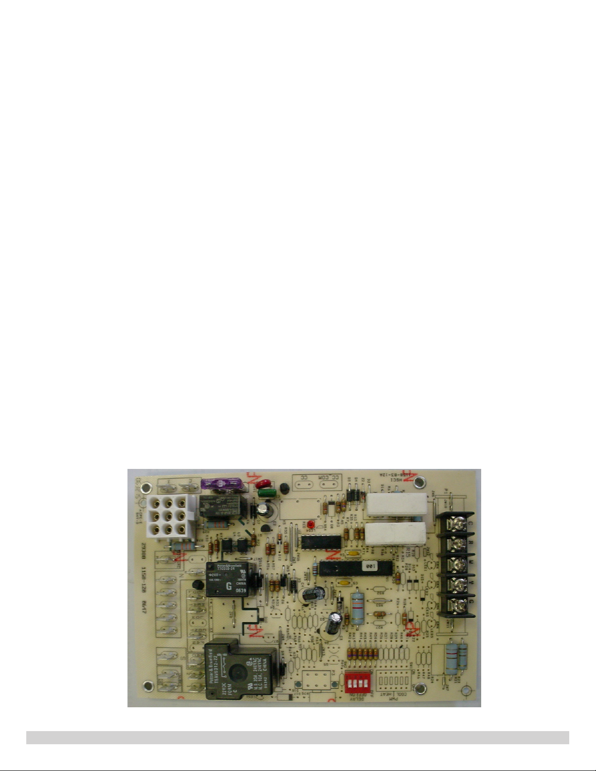
• United Technologies 1158-120 has an adjustable
fan on time set by selecting dipswitch combination
displayed in Chart 1. Fan on delay can be set at 30,
60, 90 or 120 seconds. Provides a delay between
burner ignition and blower start-up to eliminate
excessive ow of cold air when blower comes on.
• United Technologies 1158-120 has an adjustable fan
off time of 2, 3, 4 or 6 minutes as displayed in Chart
1. Fan off delay time starts when burner motor is deenergized at end of call for heat. Blower shutdown
is delayed to remove any residual heat from heat
exchanger.
• Electronic fan timer board works in conjunction with
snap disc limit controls, performing a safety function,
and breaks power to oil burner primary control,
shutting off burner if furnace over-heats.
• Limit control is thermally operated and automatically
resets. Limit control is factory installed, pre-set and
is not adjustable.
• If limit control opens with United Technologies
1158-120 electronic fan control, circulating fan will
energize. When limit closes, fan off timer begins.
At the end of fan off time cycle burner is energized,
initiating normal burner cycle.
FIGURE 3: UNITED TECHNOLOGIES 1158-120 FAN TIMER BOARD
7
Page 8
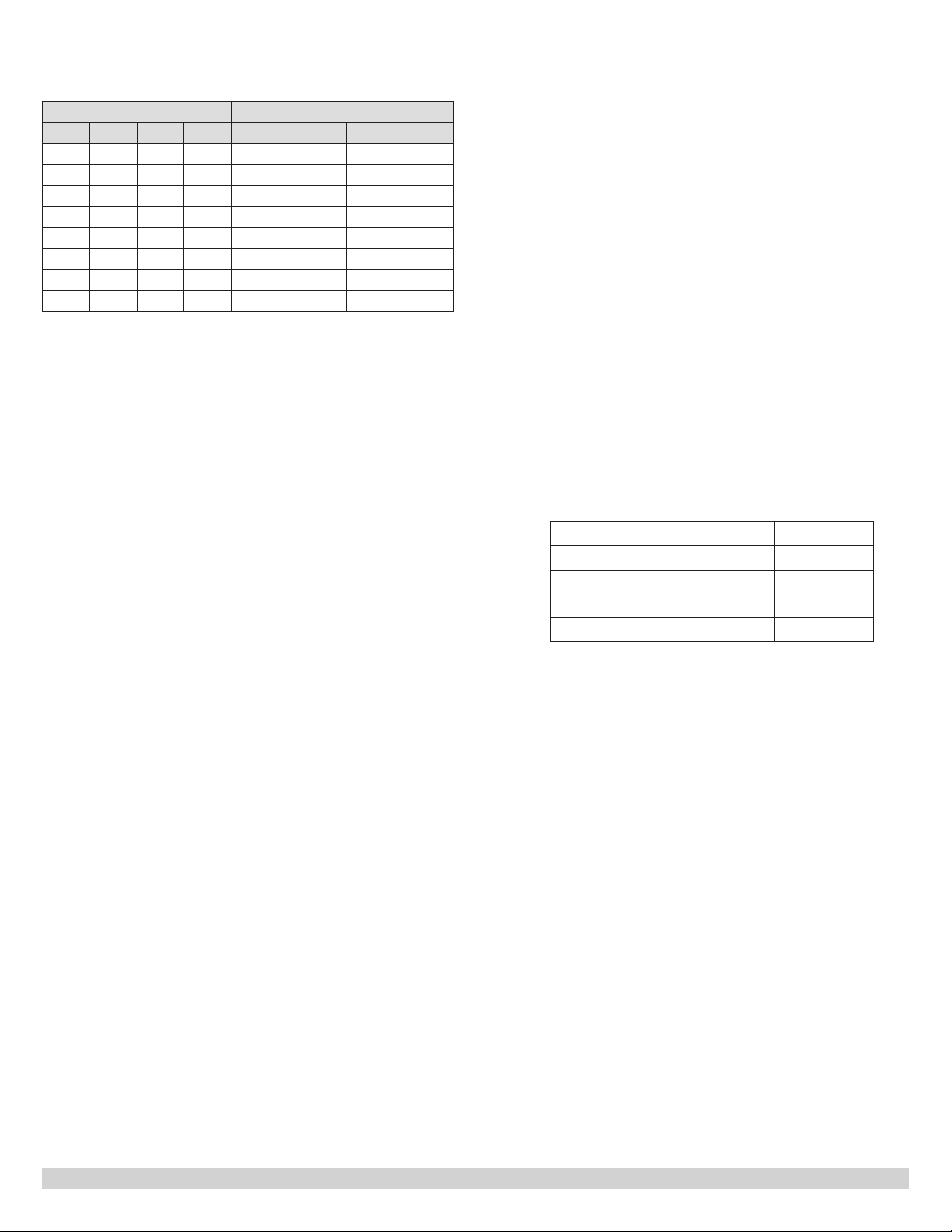
Chart 1- United Technologies 1158-120
Dip Switch Position Blower Delay Times
1 2 3 4 On Seconds Off Minutes
Off Off 30
On Off 60
Off On 90
On On 120
Off Off 2
On Off 3
Off On 4
On On 6
12. Electrical Connections
11b. Models with Mechanical Fan And Limit
Control
Furnace may be equipped with either Honeywell L4064B
or White Rodgers 5D51 fan and limit control. Temperature
sensitive fan switch is actuated by a helical bi-metal
sensing element enclosed in a metal guard, and controls
the circulating air blower. This provides a delay between
burner ignition and blower start up to eliminate excessive
ow of cold air when blower comes on.
Blower shutdown is also delayed to remove any residual
heat from heat exchanger and improve annual efciency
of the furnace. Fan on settings of 110º F to 130º F (43º C
to 55º C) and fan off settings of 90º F to 100º F (32º C to
37ºC) will usually be satisfactory.
Limit switch performs safety function and breaks power
to oil burner primary control, which shuts off the burner if
furnace over-heats. Limit control is thermally operated and
automatically resets.
Limit control is factory installed, pre-set. Limit control
incorporates a limit stop which prevents the limit switch
from being set above the factory setting. Do not tamper
with or attempt to adjust limit stop. The limit control should
be set at or below the factory setting. DO NOT SET LIMIT
CONTROL ABOVE FACTORY SETTINGS.
Model Factory Limit Control Setting
BCL-S 230°F
BFL 190°F
BCL High Capacity 200°F
Limit control and fan control are incorporated in same
housing and are operated by the same thermal element.
• Furnace is listed by Canadian Standards Association
under NRTL (North American) Standard.
• All eld wiring shall conform to CAN/CSA C22.1
Canadian Electrical Code, Part 1, and by local codes,
where they prevail.
• United States, wiring shall conform to National Fire
Protection Association NFPA-70, National Electrical
Code, and with local codes and regulations.
• Wire furnace to separate dedicated circuit in main
electrical panel.
• Suitably located circuit breaker can be used as
service switch, separate service switch is advisable.
• Service switch is necessary if circuit breaker is close
to the furnace, or furnace is located between circuit
breaker and entry to furnace room.
• Clearly mark service switch. Install in accessible area
between furnace and furnace room entry. Locate so
as to reduce possibility it can be mistaken as light
switch or similar device.
• Power requirement is: 120 VAC, 1 Ø, 60 Hz.
Factory Equipped Blower
Amps
1/3 and 1/2 HP 12
3/4 HP Belt Drive
and 1 HP Direct Drive
15
1 HP Belt Drive 20
• Accessories requiring 120 VAC power sources such
as electronic air cleaners and humidier transformers
may be powered from furnace circuit, or from
electronic fan timer board where provisions have
been made for such connections, but should have
their own controls.
• Do not use direct drive motor connections as a power
source, there is risk of damaging accessories.
• Thermostat wiring connections are shown in wiring
diagrams in Appendix B. Some micro-electronic
thermostats require additional controls and wiring.
Refer to thermostat manufacturer's instructions.
• Locate thermostat approximately 5 feet above oor,
on inside wall, and where thermostat is exposed to
average room temperatures. Avoid locations where
thermostat is exposed to cold drafts, heat from
nearby lamps and appliances, exposure to sunlight,
heat from inside wall stacks, etc.
• Adjust thermostat heat anticipator to amperage
draw of heating control circuit as measured at "R"
and "W" terminals of thermostat. Do not measure
current with thermostat connected to the circuit.
Measure amperage by connecting ammeter between
two wires which connect to thermostat "R" and "W"
terminals.
8
Page 9

13. Humidier
• Humidier is optional accessory available through
most heating supplies outlets.
• Follow humidier manufacturer's installation
instructions
• Protect furnace heat exchanger from water or water
droplets from humidier.
• Do not use direct drive motor connections as source
of power for 120 VAC humidiers and humidier
transformers.
14. Piping Installation
• Install fuel system in accordance with requirements
of CAN/CSA B-139, and local regulations.
• United States installation shall conform to NFPA No.
31 and local codes and authorities.
• Use only approved fuel oil tanks, piping, ttings and
oil lter.
• Install oil lter as close to burner as possible.
• Refer to instructions and illustrations in oil burner and
oil pump instructions shipped with the furnace.
15. Oil Filter
Install oil lter between fuel oil storage tank and oil burner.
When using oil burner nozzle smaller than 0.65 U.S.
Gallons Per Hour, install additional 7 to 10 micron lter as
close as possible to oil burner.
16. Oil Burner Nozzles
Furnaces are certied for multiple ring rates. Furnace
may be red at ideal rate for wide range of structures by
manipulating oil burner, nozzle, ame retention head, and
temperature rise. Refer to Table A-1 thru A-3, and furnace
rating plate to determine proper combinations.
NOTICE
Set up sidewall vented models to deliver zero (0)
smoke.
NOTICE
Before operating furnace check burner alignment
with combustion chamber. End cone of air tube must
be centred to accommodating ring of combustion
chamber. Adjust as necessary.
18. Burner Electrodes
Correct positioning of electrode tips with respect to each
other, fuel oil nozzle, and burners is essential for smooth
light ups and proper operation.
Refer to oil burner instructions provided with furnace and
Appendix A Section A.2 for electrode specications.
NOTICE
Do not tamper with furnace controls they are
sensitive. If problems persist, call your service
contractor.
19. Burner Primary (Safety) Control
Furnace is equipped with primary combustion control, also
referred to as burner relay or burner protector relay, which
uses a cad cell located in burner housing, to monitor and
control combustion.
Dust or combustion residuals can build up on lens of
cad cell impairing its response to ame. Check cad cell
for cleanliness and proper alignment if primary control
frequently shuts down combustion.
17. Oil Burner Adjustment
• Adjust burner air supply to maintain fuel to air ratio
to obtain ideal combustion conditions.
• Lack of air causes "soft" and "sooty" ames, resulting
in soot build-up throughout heat exchanger passages.
• Excess combustion air causes bright roaring re and high
stack temperatures resulting in poor fuel efciency.
• Furnaces operate most efciently with No. 1 smoke
spot on Bacharach Scale. Dust will eventually build
up on air moving components of oil burner assembly
resulting in decreased air supply with potential soot
build up in ue gas passageways of heat exchanger.
Soot behaves as insulator and impairs good heat
transfer. Stack temperature increases, and efciency
decreases. To avoid this problem, adjust the air
supply to provide no more than trace smoke spot on
Bacharach Scale.
• See Venting Instructions included in Vent Kits for setup details for sidewall vented furnaces.
20. Combustion Chamber
Furnace is equipped with cerafelt combustion chamber, held
in place by a retaining bracket.
Check the alignment of the combustion chamber
and oil burner before ring. It is possible for the
combustion chamber to shift if subjected to rough
handling during transit.
Inspect combustion chamber for damage or carbon build
up whenever oil burner is removed for repairs or routine
maintenance.
9
Page 10
WARNING
!
Fire, burn, asphyxiation hazard. Do not start the
burner unless blower access door is secured in
place. Failure to follow these instructions could
result in death or serious injury.
21. Circulating Air Blower
• BCL-S and BFL furnace models may be equipped with
either direct drive or belt drive blower systems.
• BCL high capacity furnace models are equipped with
belt drive blower systems.
• All models are equipped with PSC blower motors.
Direct Drive Blower Systems
• Direct drive blower speed adjustments are not
normally required in properly sized extended plenum
duct systems. Motor RPM and air CFM delivery will
vary automatically to accommodate conditions within
usual range of external static pressures typical of
residential duct systems.
• Under-sized duct systems may require higher blower
speed to obtain system temperature rise.
• Some older duct systems were not designed to provide
static pressure. They typically feature special reducing
ttings at each branch run and lack block ends on the
trunk ducts. These systems may require modication
to provide some resistance to the airow to prevent
over-amping of direct drive blower motor. Selecting a
lower blower speed may correct this problem.
• Direct drive blower speeds are adjusted by changing
"hot" wires to motor winding connections. Refer to
wiring diagrams in Appendix B or wiring diagram label
afxed to furnace.
• Do not move neutral wire (normally white wire)
to adjust blower speed.
• Single blower speed for both heating and cooling
modes may be used. Use a "piggy-back connector"
accommodating both wires on a single motor tap.
• It is also acceptable to connect selected motor speed
with a pigtail joined to both heating and cooling speed
wires with a wire nut.
• Safety precaution against accidental disconnection of
wires by vibration, secure wire nut and wires with few
wraps of electricians tape.
• Do not connect power leads between motor
speeds. Always connect neutral wire to motor's
designated neutral terminal.
• If joining blower speed wiring is done in furnace
junction box, tape off both ends of unused wire.
• Do not use blower speed wires as source of
power to accessories as electronic air cleaners
and humidier transformers. Unused motor
taps auto-generate sufciently high voltages to
damage accessory equipment.
Belt Drive Blower Systems
WARNING
!
Improper installation could result in death or serious
injury. Belt drive components operate at high speeds
and may snag loose clothing resulting in injury or
death. Have a trained service professional preform
the following instructions. Failure to follow these
instructions could result in death or serious injury.
Belt drive blower systems can be modied for speed and
air delivery by adjusting variable speed motor pulley and
changing blower pulley.
• Adjust variable speed motor pulley by loosening 5/32
allen set screw in outer sheave. Turn outer sheave
clockwise to increase blower speed, counter clockwise
to reduce speed.
• Verify setscrew is tightened at one of the at spots,
failure to do so will convert the variable speed pulley
to a xed speed pulley by ruining the threads.
• Modify blower speed by changing the blower pulley.
Smaller blower pulley will cause the blower to turn
faster. Large pulley reduces blower speed.
• Large increases in the blower speed may increase
power requirements.
• Check amperage draw of the blower motor after
making changes. If amperage draw is greater than
the value listed on the motor rating plate, replace
with motor of higher horsepower.
• Deection of 3/4 of an inch to 1 inch fan belt tension
is necessary. Less deection places a strain on the
blower bearings and increases start up amperage
draw.
• More deection allows excess slippage and causes
premature motor pulley wear.
• Automotive belt dressings are not recommended.
• Bar soap will work as belt dressing to reduce belt
squeaks, etc. If using soap apply to the sides of belt
only.
If operating belt drive blower at speeds above 1100
RPM, replace sintered bronze blower bearings with roller
bearings.
Blower assembly in BCL (170-2/190/200/225) models with
1 HP blower is equipped with roller bearings.
10
 Loading...