

Page 1
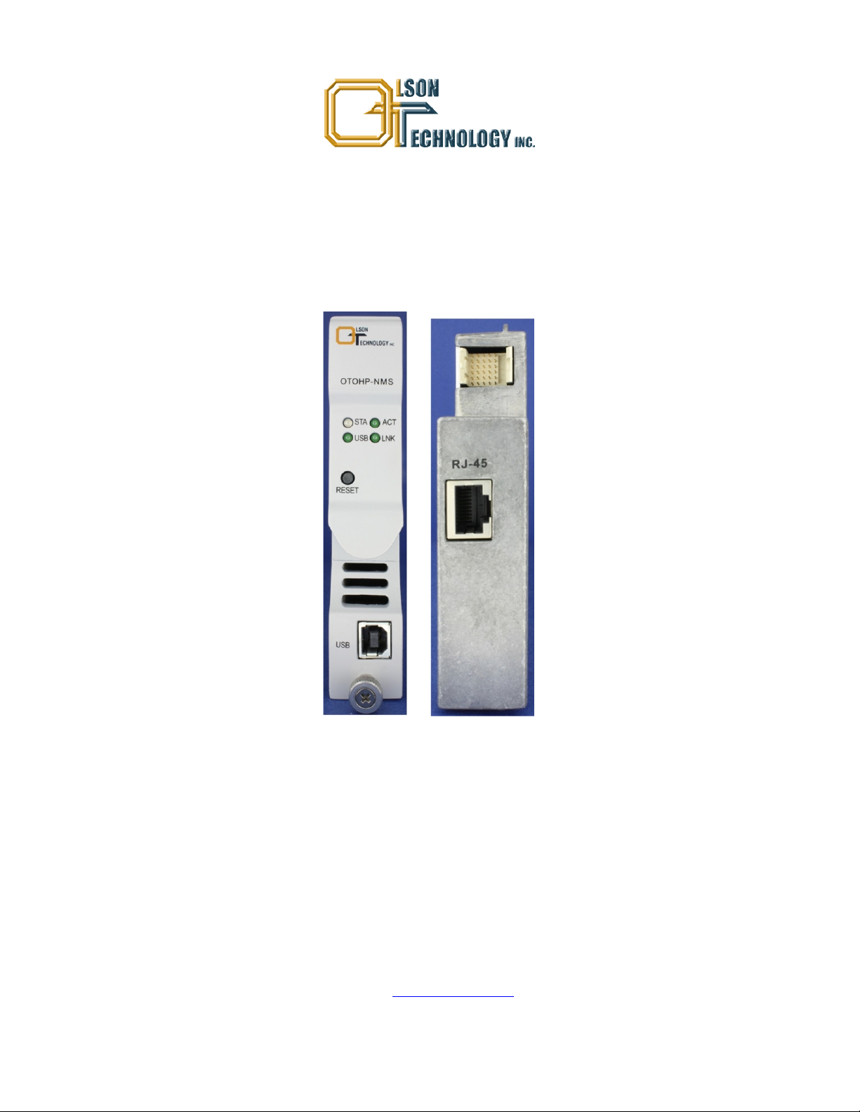
Model OTOHP-NMS Network Management System
Software User Guide
24926 Highway 108
Sierra Village, CA 95346
Phone: (800) 545-1022
Fax: (209 586-1022
Rev. X1 E-Mail: [email protected]
11/15/2010
Page 2

TABLE OF CONTENTS
INSTALLATION .........................................................................................................................................................4
System Requirements ............................................................................................................................................4
Installing the Software ............................................................................................................................................4
GETTING STARTED..................................................................................................................................................7
Start the Program ...................................................................................................................................................7
Language Selection................................................................................................................................................7
Adding a Device to the IP Manager........................................................................................................................8
MENUS AND WINDOWS...........................................................................................................................................9
View the MIB Browser ............................................................................................................................................9
Loading/Unloading MIB Files................................................................................................................................10
Setting SNMP Parameters....................................................................................................................................10
Google Map..........................................................................................................................................................11
Ping Tool...............................................................................................................................................................12
Log Viewer Tool....................................................................................................................................................13
Query Database Tool............................................................................................................................................14
Check for Updates Tool........................................................................................................................................16
Options Tools........................................................................................................................................................17
User Manager.......................................................................................................................................................19
Plug-in Manager ...................................................................................................................................................19
Personal Web Server............................................................................................................................................19
Firmware Update Wizard......................................................................................................................................20
DEVICE IP MANAGER ............................................................................................................................................21
SNMP Entities Setup............................................................................................................................................22
Polling Queue .......................................................................................................................................................22
Receive Trap ........................................................................................................................................................23
3RU SERIES DEVICE..............................................................................................................................................25
Adding Tool Tips...................................................................................................................................................25
OTOHP-NMS Network Management System Module .........................................................................................26
OTOHP-RRX-04 Quad Reverse Return Path Receiver Module..........................................................................27
OTOHP-RRX-02 Dual Reverse Return Path Receiver Module............................................................................28
OTOHP-FTX Forward Path CATV Transmitter Module .......................................................................................29
OTOHP-FRX Forward Path Receiver Module......................................................................................................30
OTOHP-EDFA Module .........................................................................................................................................31
OTOHP-RFG Quad RFoG Receiver Module........................................................................................................32
OTOHP-PS Power Supply Module.......................................................................................................................33
1RU SERIES DEVICE..............................................................................................................................................34
1RU Transmitter ...................................................................................................................................................34
Four-Port Optical Node.........................................................................................................................................35
EOC MEDIA CONVERTERS...................................................................................................................................36
NMC......................................................................................................................................................................36
1000EAS...............................................................................................................................................................36
Model OTOHP-NMS User Guide, Rev. X1 www.olsontech.com
2
Page 3

EOC SWITCH...........................................................................................................................................................37
Chassis.................................................................................................................................................................37
Ports......................................................................................................................................................................37
ATTACHING A DATABASE FILE TO SQL SERVER.............................................................................................38
SQL Server 2000..................................................................................................................................................38
SQL Server 2005..................................................................................................................................................38
Model OTOHP-NMS User Guide, Rev. X1 www.olsontech.com
3
Page 4
INSTALLATION
System Requirements
• Supported Operating Systems: Windows 7; Windows Server 2008; Windows Vista; Windows Server 2003;
Windows XP
• Processor: 400 MHz Pentium processor or equivalent (Minimum); 1GHz Pentium processor or equivalent
(Recommended)
• RAM:96Mb (Minimum); 256Mb (Recommended)
• Hard Disk: Up to 500Mb of available space may be required
• Display: 800 x 600, 256 colors (Minimum); 1024 x 768 high color, 32-bit (Recommended)
Installing the Software
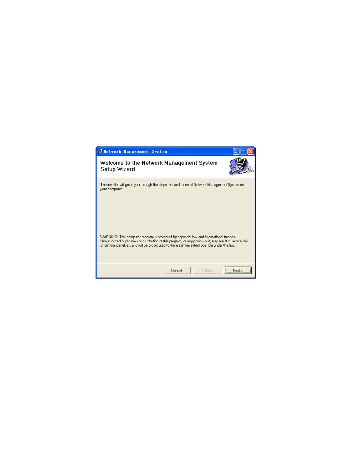
1) Launch “setup.exe” to begin the installation. Click “Next” to go to the next step.
2) Select the desired folder where the software will be installed. To install in default folder, click “Next.” To install to a
different folder, enter the name of the folder or click “Browse” and navigate to the desired folder.
Model OTOHP-NMS User Guide, Rev. X1 www.olsontech.com
4
Page 5

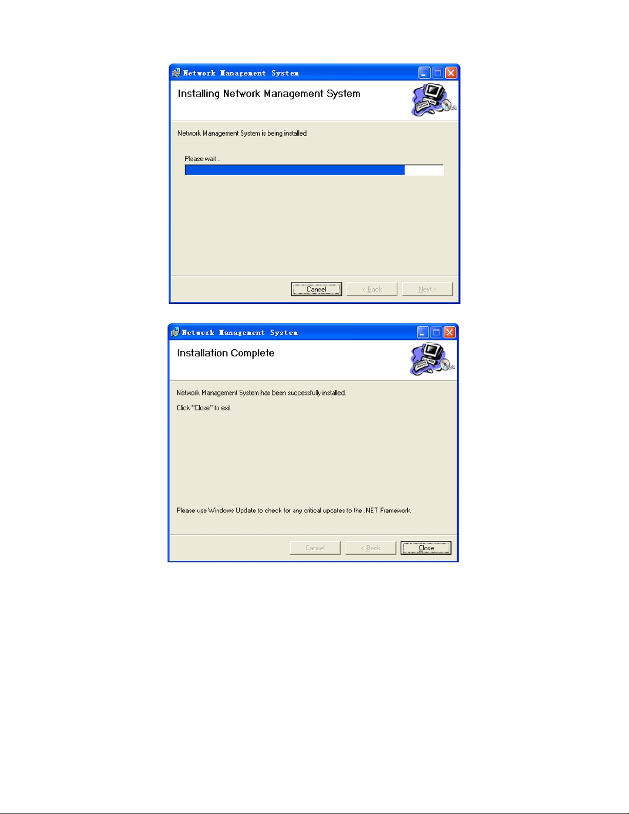
3) Click “Next” to confirm the installation settings. The software will begin to install.
4) When the “Installation Complete” screen appears, click close to exit the installation. The software is now ready to be
configured.
Model OTOHP-NMS User Guide, Rev. X1 www.olsontech.com
5
Page 6
Model OTOHP-NMS User Guide, Rev. X1 www.olsontech.com
6
Page 7
GETTING STARTED
Start the Program
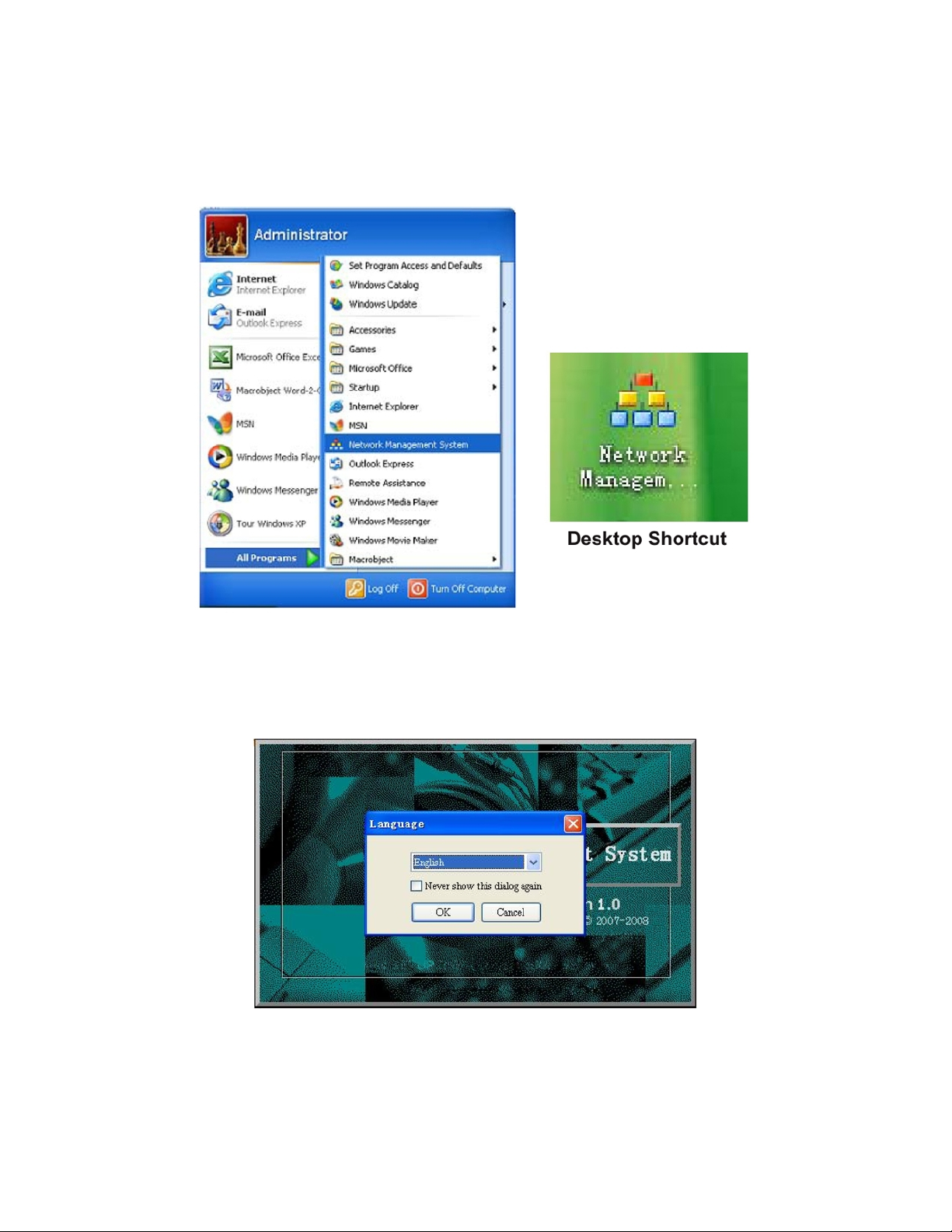
Select “start” -> “Programs” -> Network Management System, or click desktop shortcut.
Language Selection
Select the preferred language for the program. The default language is English. Select “Never show this dialog again” to
remember the selection. The software will launch using this language.
Model OTOHP-NMS User Guide, Rev. X1 www.olsontech.com
7
Page 8
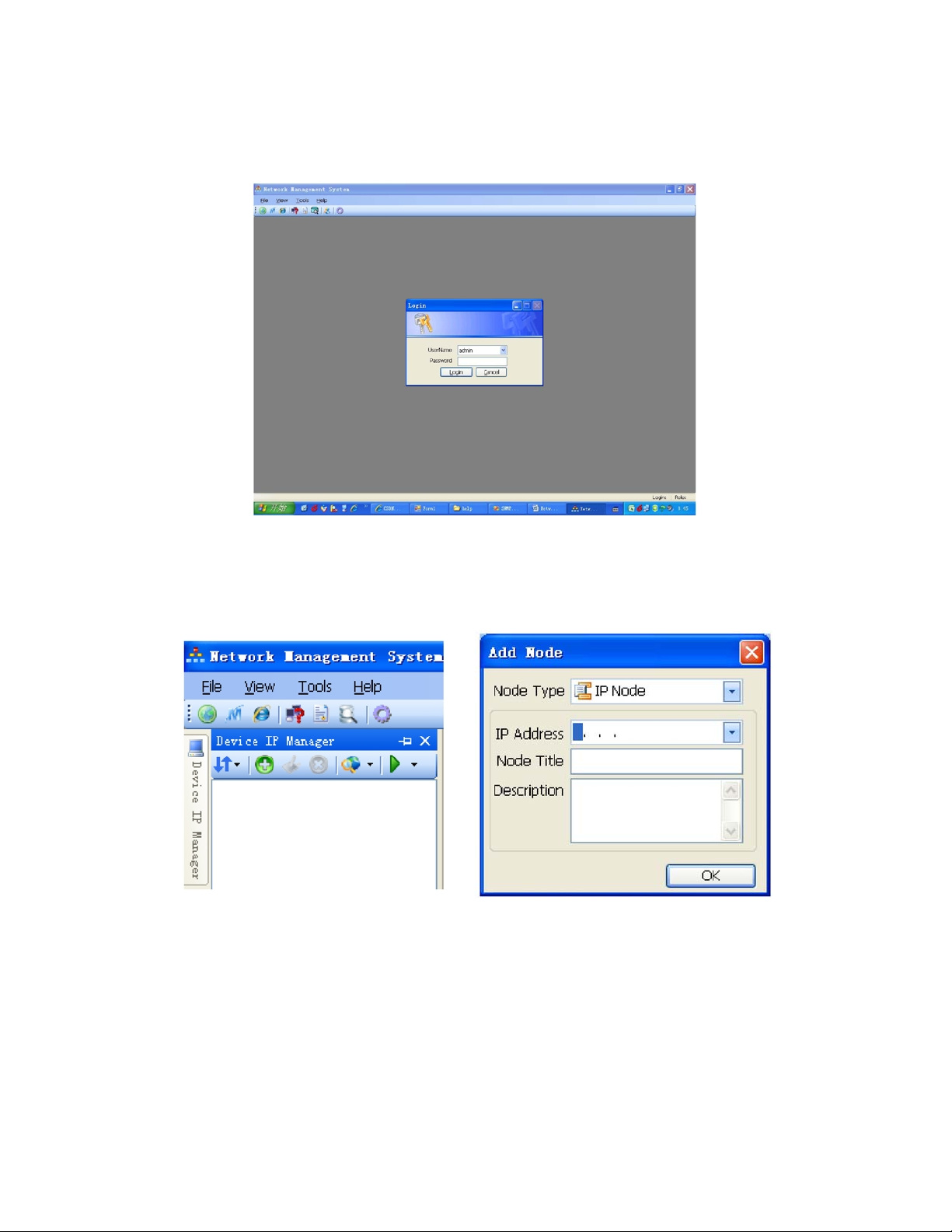
Setting the Login Information
The program requires a username and password to be used. By default, the username is “admin” and the password is also
“admin”.
Adding a Device to the IP Manager
Click the green “+” button on the tool bar to open the “Add A Node” window. Type in the IP address of the device to be
added as well as a title and brief description of the device. Click “OK” to continue
Click on the green arrow on the right side of the tool bar to poll the newly added device.
Model OTOHP-NMS User Guide, Rev. X1 www.olsontech.com
8
Page 9
MENUS AND WINDOWS
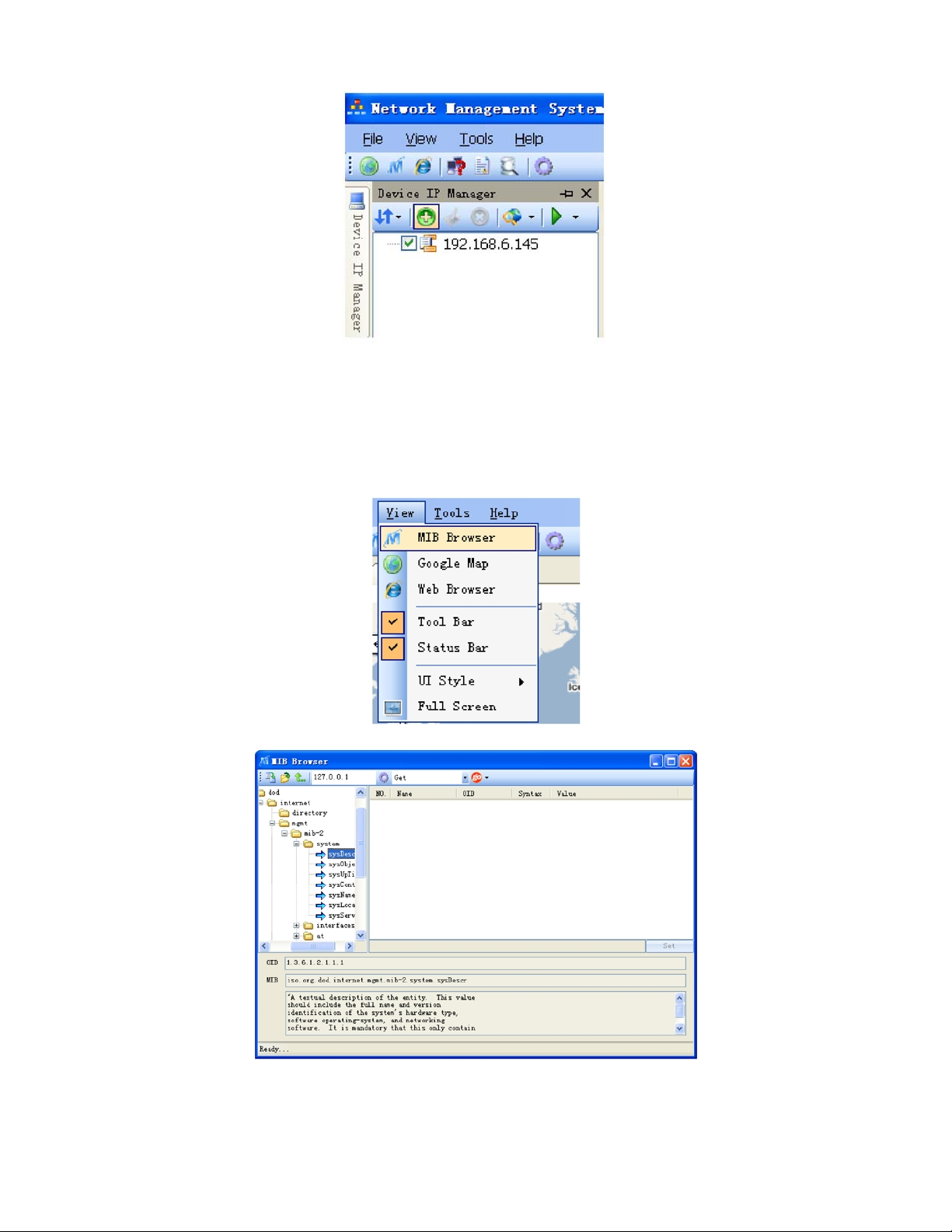
View the MIB Browser
The MIB browser allows the user to load or unl oad an MIB file . The soft ware sup ports SNM P v1, v2c and v3 protocols and
can send the following SNMP commands: get, getnext, set, walk, getbulk.
Model OTOHP-NMS User Guide, Rev. X1 www.olsontech.com
9
Page 10
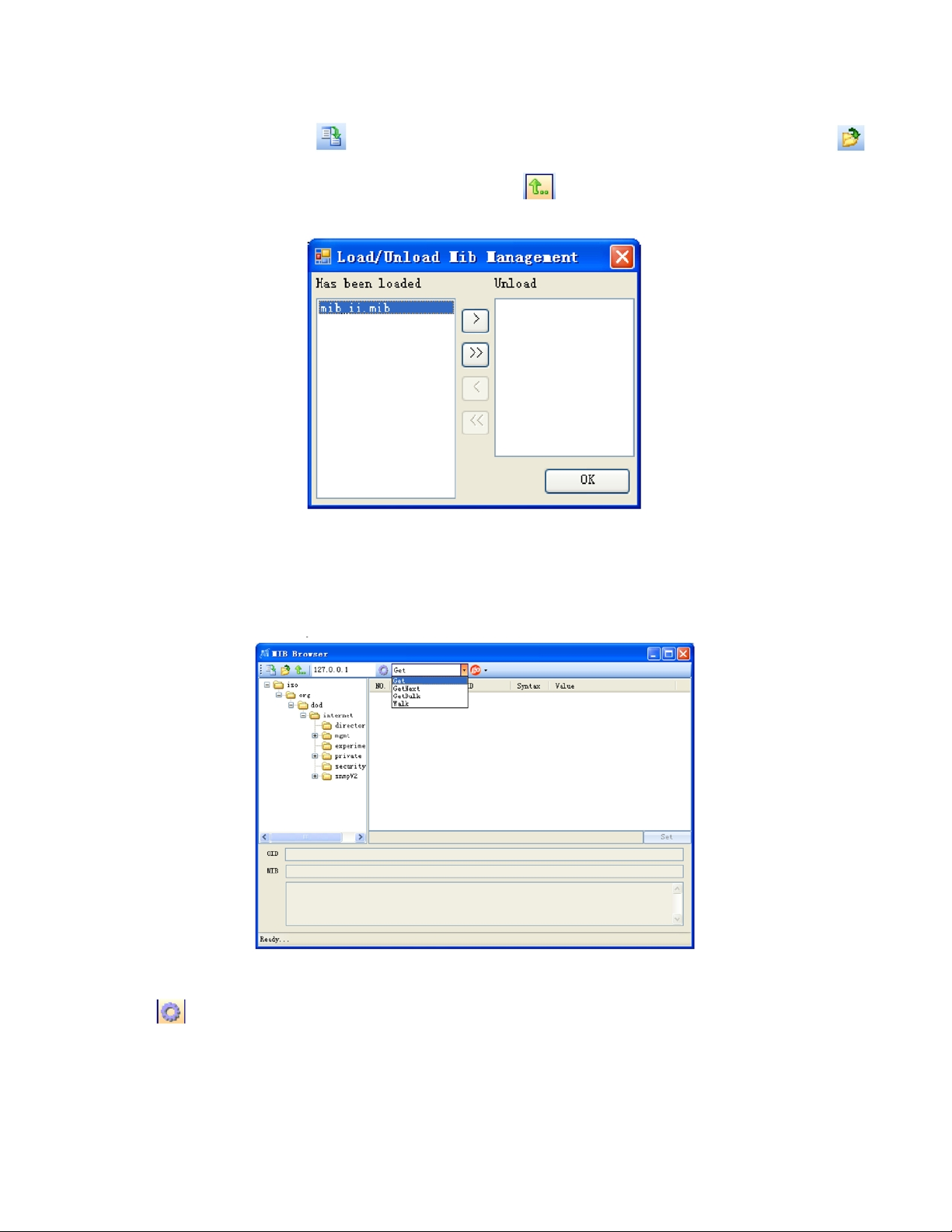
Loading/Unloading MIB Files
To load a single MI B f ile, us e th e
icon to browse to the directory that contains the MIB files. Use the
icon on the MIB browser window. To select more than one MIB file, use the
icon to unload MIB files from the system.
The list of files on the left shows the MIB files that have been uploaded. The list of files on the right side shows the files that
are not loaded. Use the left arrow and right arrow to select the file( s) you wish to load/unload. Press “O K” to confirm the
action. You m ay also select a node of the M IB tree. Use the dr op do wn menu t o select o ne of c ommands . Clic k “go” t o sen d
your command.
Setting SNMP Parameters
Use the
Model OTOHP-NMS User Guide, Rev. X1 www.olsontech.com
icon to access the screen that allows you to set the SNMP parameters.
10
Page 11
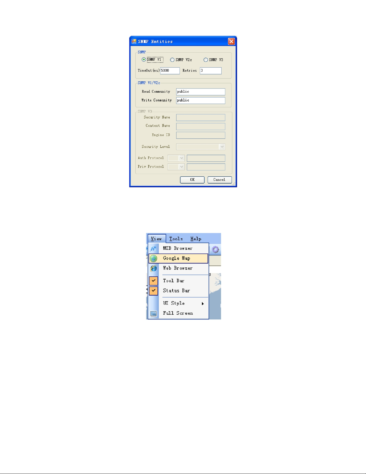
Google Map
The Google Map is available from the View drop down menu. This feature allows the user to view the location of all the
devices that have been added to the interface.
Model OTOHP-NMS User Guide, Rev. X1 www.olsontech.com
11
Page 12
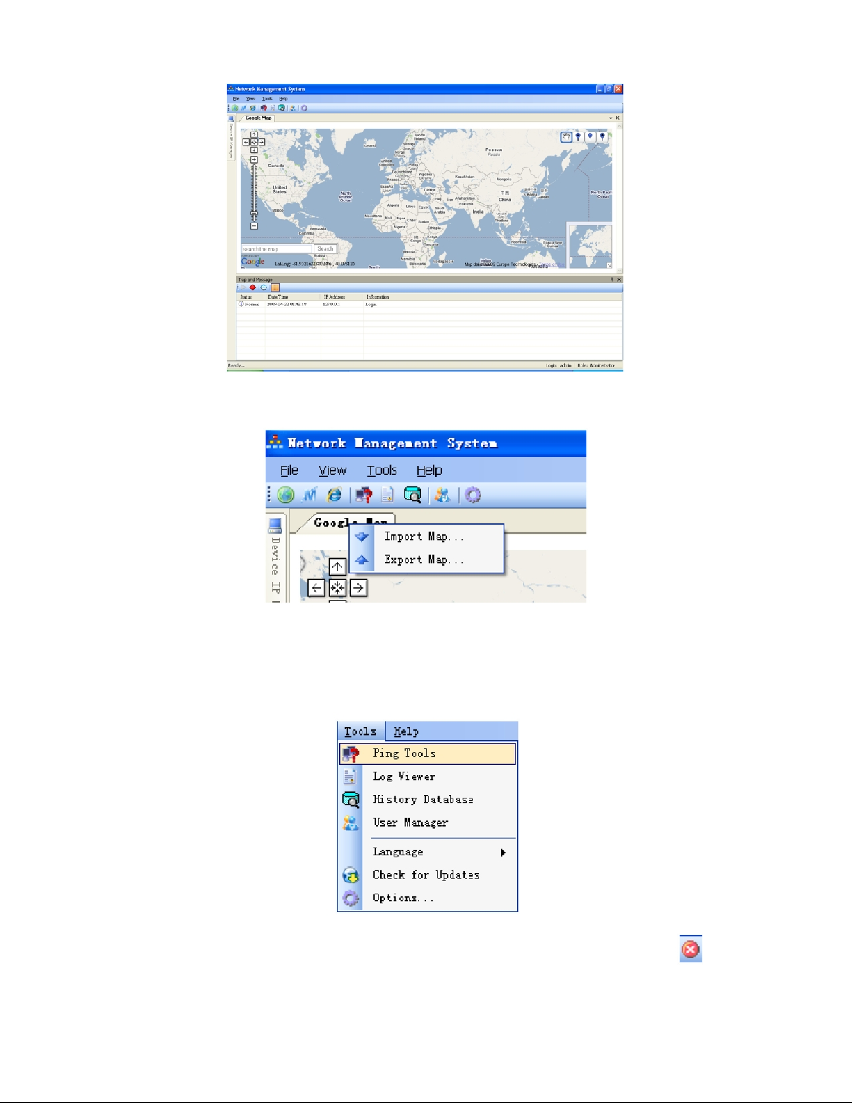
Use the Google Map Import/Export feature to import a new map or export the existing map.
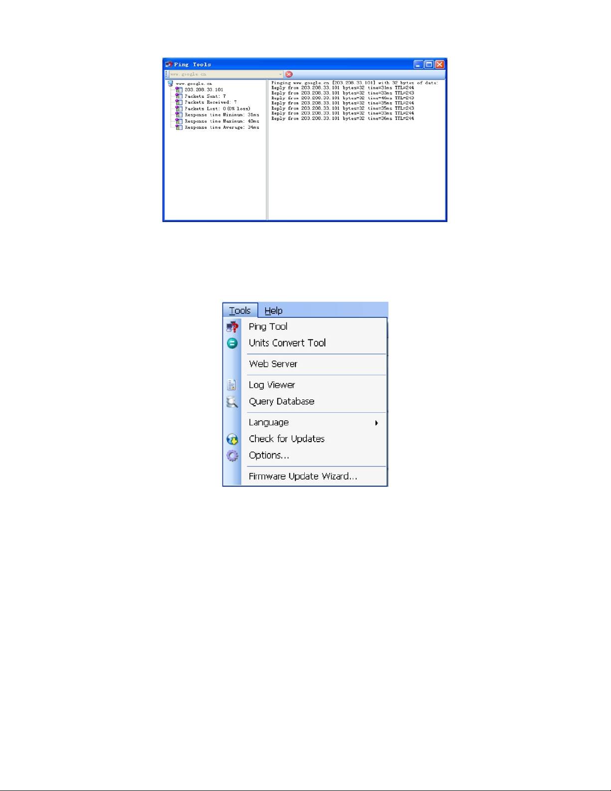
Ping Tool
The ping tool is accessed from the Tools menu. The Ping tool functions like a Windows “ping.exe” command. It is used to
verify that the computer can connect to other host devices.
Enter the IP address or domain of the device you wish to pint then click “go” to ping the device. Use the
the ping.
Model OTOHP-NMS User Guide, Rev. X1 www.olsontech.com
icon to stop
12
Page 13
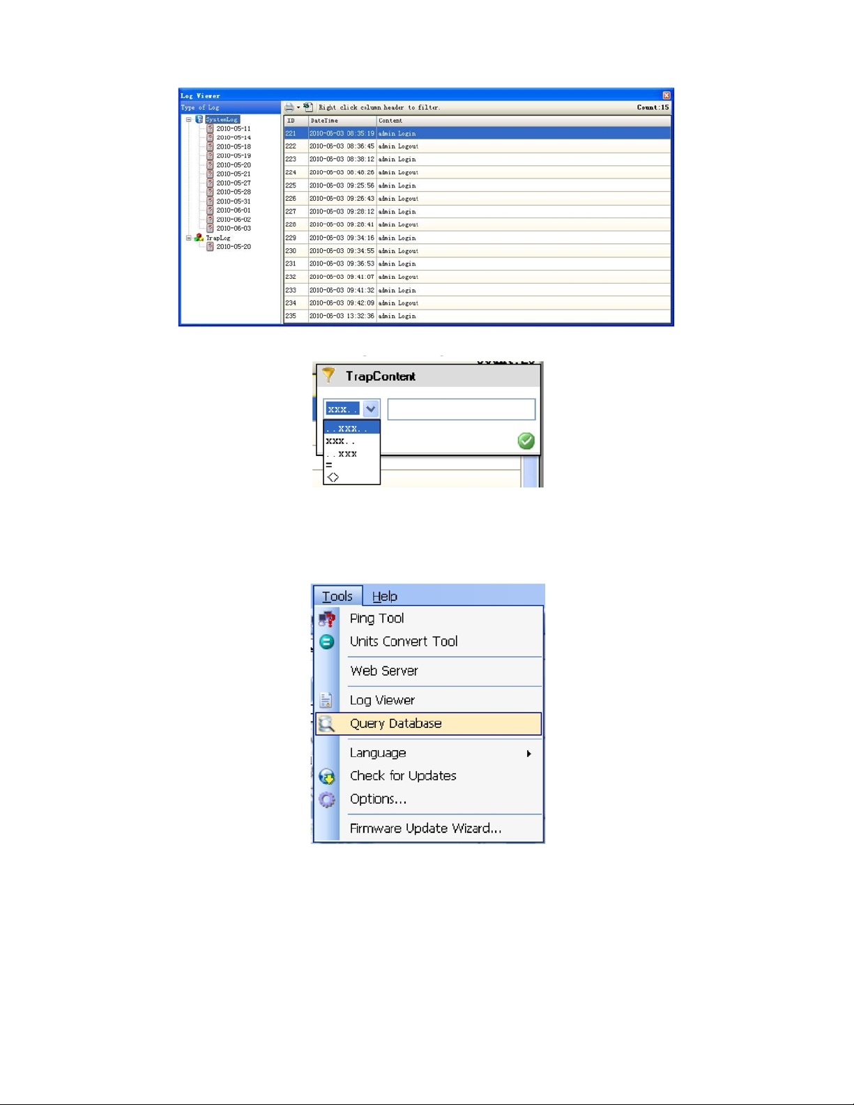
Log Viewer Tool
The Log View Tool allows the user to view log message while the program is running. Log entries are grouped by
date.
To view log content: double click the date node on the left side, the log content will be shown on the right side. To delete a
log: select the log content that you want to delete, then select delete from context menu command. To filter the log content,
right click on the column header.
Model OTOHP-NMS User Guide, Rev. X1 www.olsontech.com
13
Page 14
Query Database Tool
This tool allows the user to query data from the database. Data can then be exported an Excel spreadsheet or printed.
To perform a Simple Query, follow the steps below.
1) Select database type (Microsoft Access or Microsoft SQL Server);
2) Fill in the necessary database parameters, including the file path, SQL server name, login user name and password,
and select the catalog;
3) Select the name of the table that you wish to query;
4) Select “Field” to display;
5) Enter the desired conditions to query your data quickly.
Model OTOHP-NMS User Guide, Rev. X1 www.olsontech.com
14
Page 15
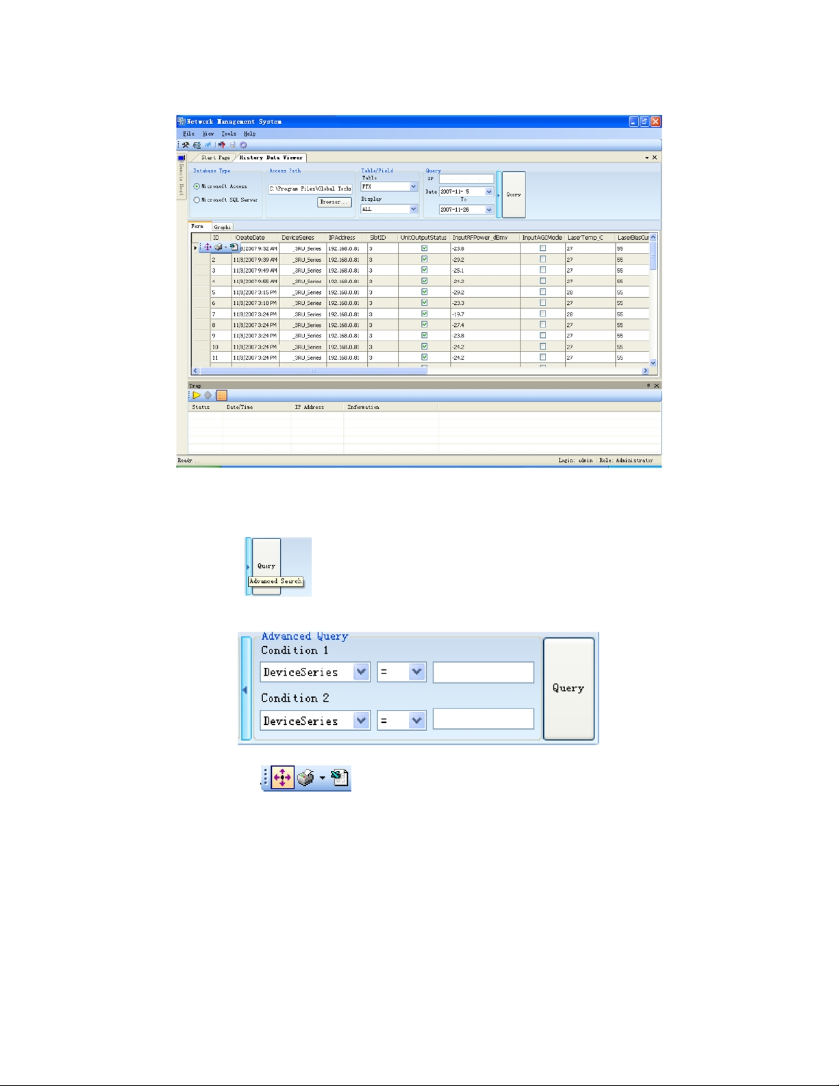
6) Click “Query”.
To perform an Advanced Query, follow the steps below.
1) Perform a Simple Query by following step1 to step5 above;
2) Click the split button
to get more conditions.
The Pint/Export: Float toolbar
can be used to print and export.
The “Graphic” tab on the “Query Database” screen can be used to view a graphical representation of the data.
Model OTOHP-NMS User Guide, Rev. X1 www.olsontech.com
15
Page 16
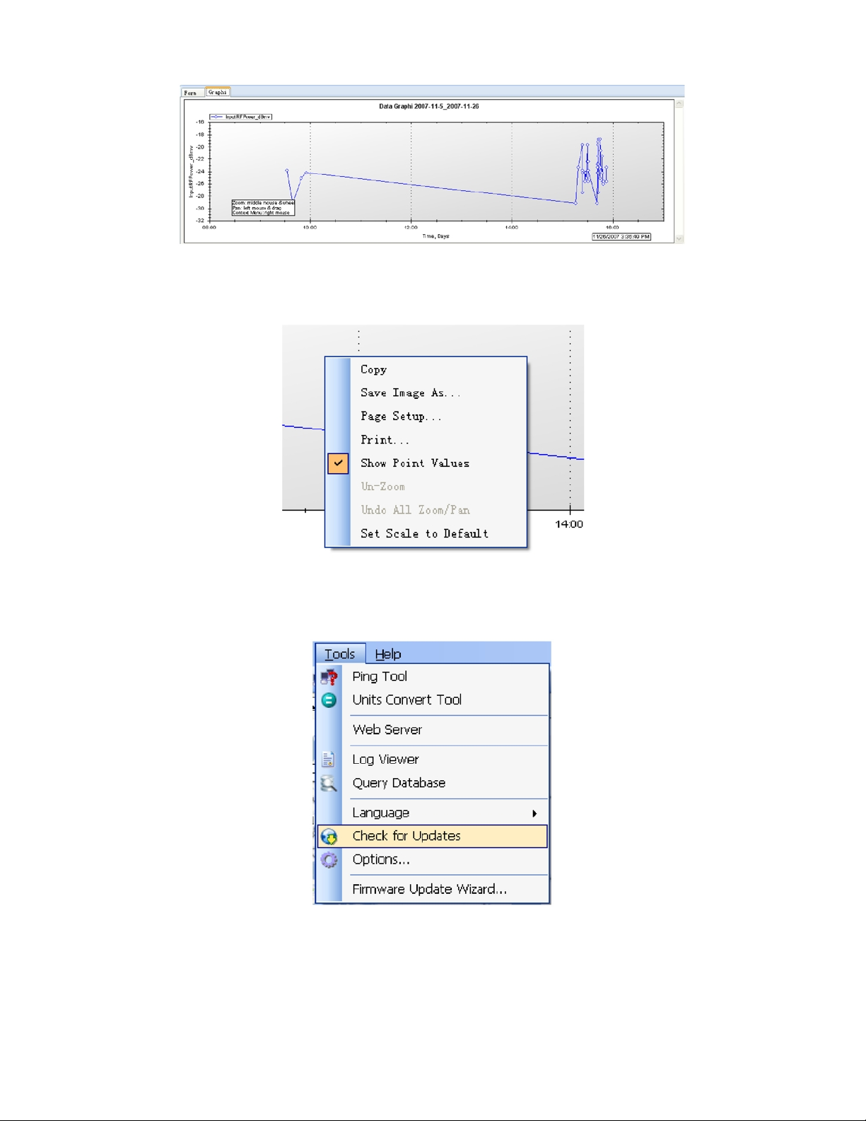
To view point values on the chart, move the mouse over the point you wish to view and right click to display the point
values.
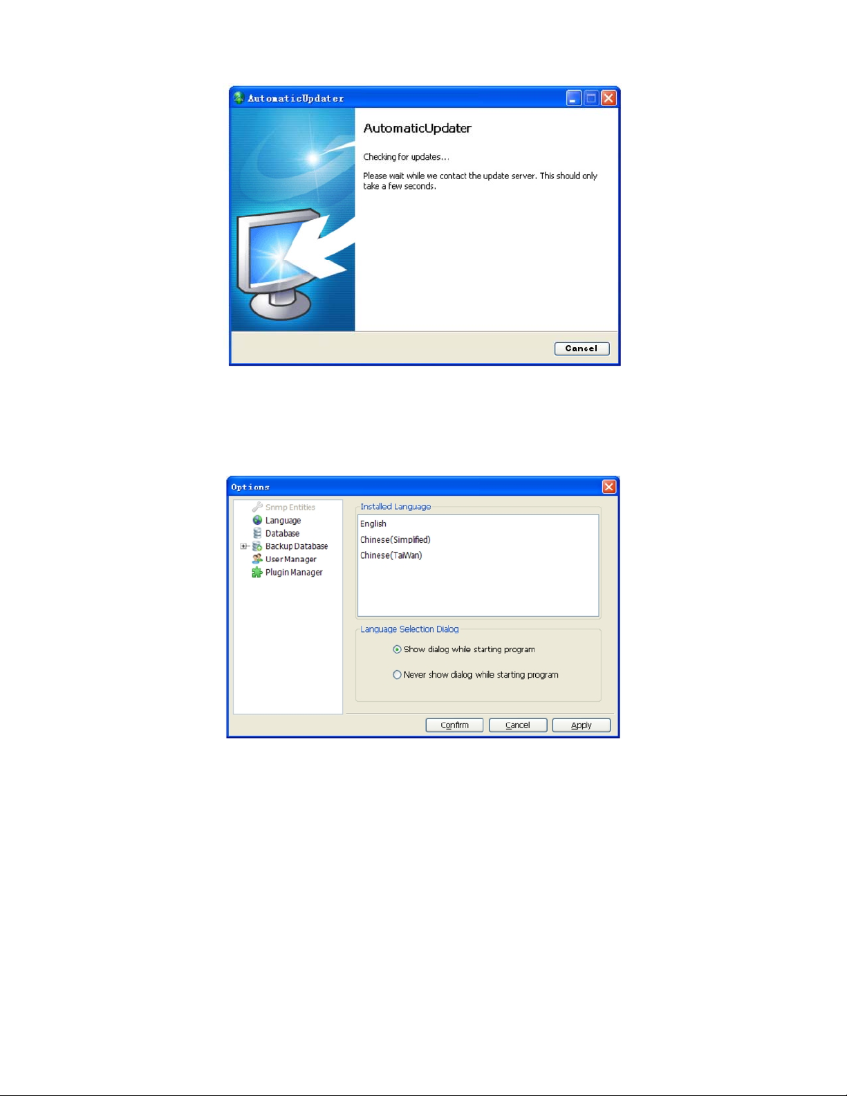
Check for Updates Tool
Use the Check for Updates to see if there is a new version of this program and to update your program to a new version.
The computer must be connected to the Internet in order to use the Check for Updates tool.
Model OTOHP-NMS User Guide, Rev. X1 www.olsontech.com
16
Page 17
Options Tools
The options menu allows the user to set a variety of system options, including SNMP entities, language, database settings,
backup database parameters, users, plug-ins, personal web server and firmware update wizard.
Model OTOHP-NMS User Guide, Rev. X1 www.olsontech.com
17
Page 18
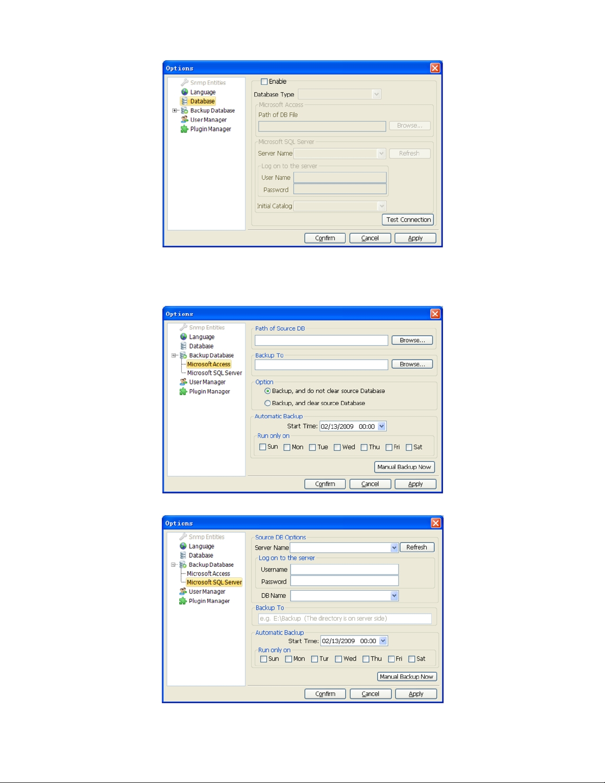
NOTE: When “Enable” is selected, the program will use the database to record data. When this box is unselected, the
program will not record data to the database.
Model OTOHP-NMS User Guide, Rev. X1 www.olsontech.com
18
Page 19
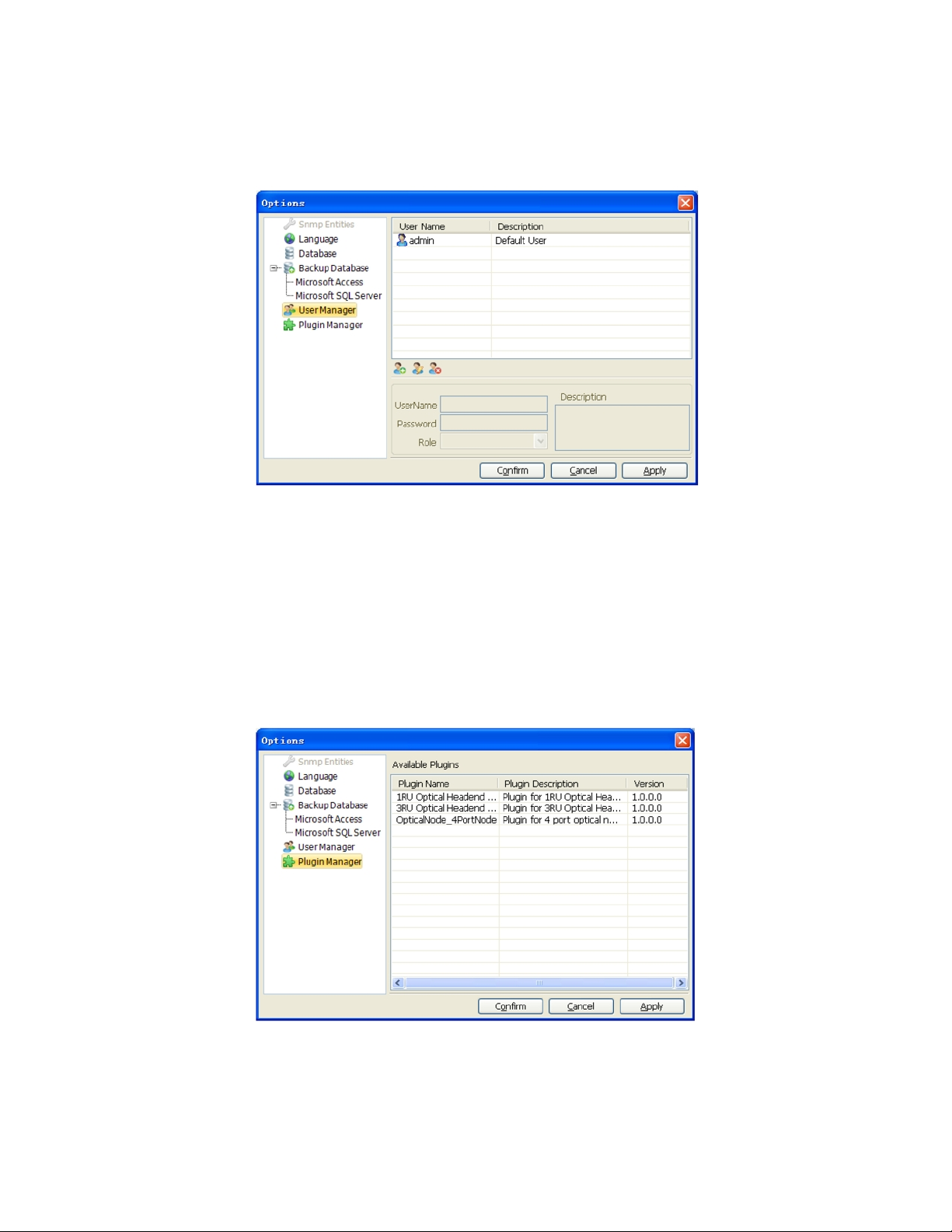
User Manager
The User Manager is available from the options menu. It allows the operator to add and remove authorized users to the
interface.
Two types of users may be specified, the Administrator and Constrained. The administrator users have full access to all of
the settings in the software. Constrained users have limited access to these features operation. Actions include:
• Add a new user: Enter a Username and Password that is between 5 and 20 characters (only administrator users can
perform this action).
• Edit a user: constrained users only can edit themselves while administrators can edit all users.
• Delete a user (only administrator users can do this action).
Plug-in Manager
Allows the user to manage plug-ins for the software.
Personal Web Server
The Personal Web Server tool allows the user to view the database and system log files from a remote location.
Model OTOHP-NMS User Guide, Rev. X1 www.olsontech.com
19
Page 20
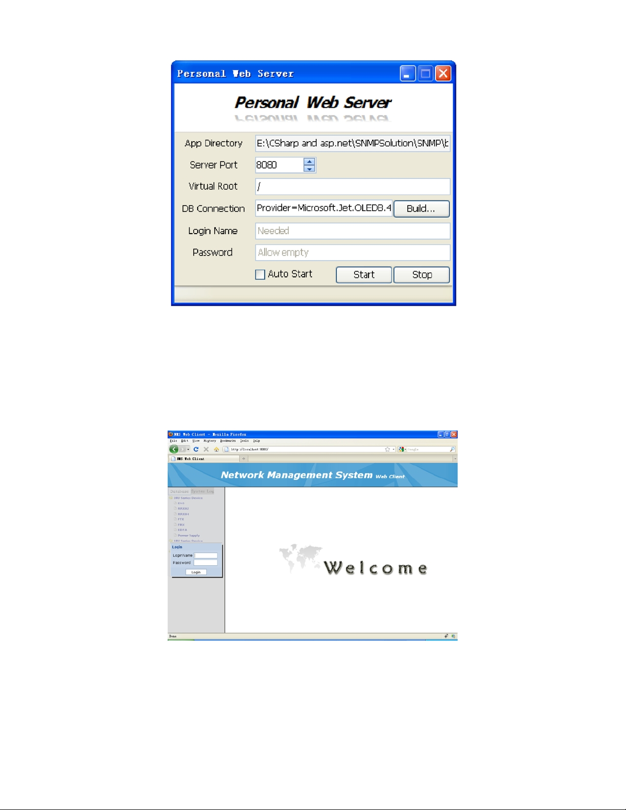
The web server settings are as follows:
1) Server Port, setup the port (>1024) which is unused.
2) Virtual Root, keep it by default.
3) DB Connection, determines which database will be viewed.
4) Login Name/Password, Authenticate the user for remote login.
5) Auto Start, if it is checked, the server will start automatically when the program starts.
Firmware Update Wizard
The Firmware Update Wizard guides the user through the firmware update process. Note that different devices may have
different wizards.
Model OTOHP-NMS User Guide, Rev. X1 www.olsontech.com
20
Page 21
DEVICE IP MANAGER
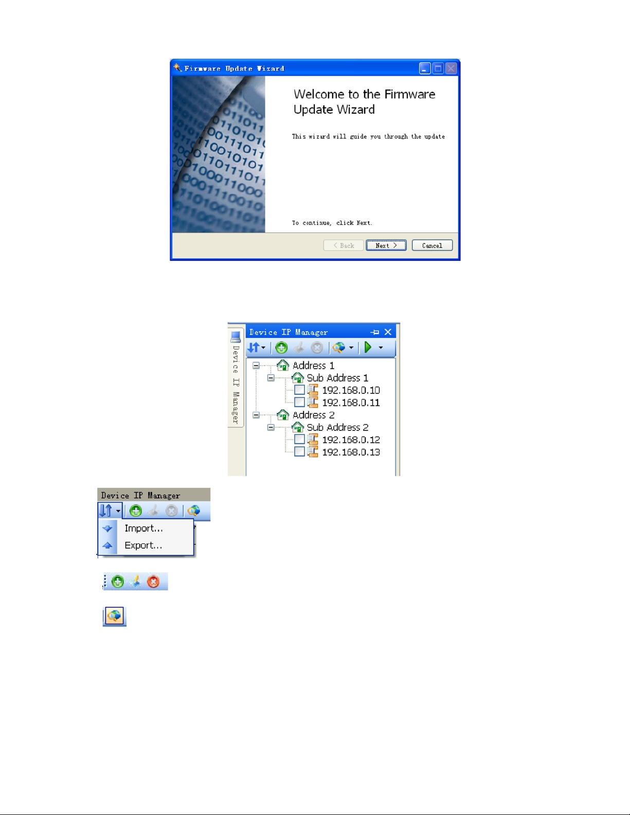
The Device IP Manager allows the user to manage the various IP addresses being monitored by the OTOHP-NMS.
Select
Use the
Use the
Model OTOHP-NMS User Guide, Rev. X1 www.olsontech.com
icon to search for a device that is within a specified range of IP addresses.
icons to add, edit, or delete IP addresses.
to import IP addresses into the system or export them to a new file format.
21
Page 22
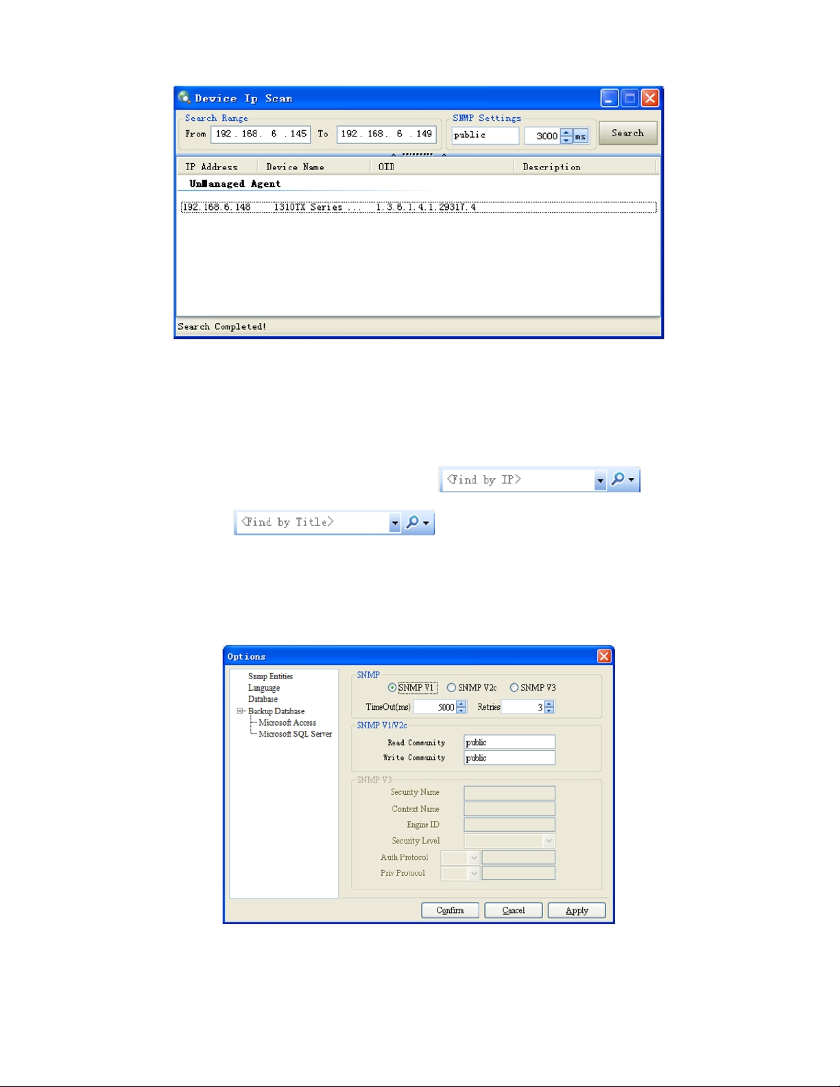
The result will be group by:
i. Managed Agent, means that devices are managing now.
ii. Unmanaged Agent means that devices are not managed yet.
iii. Unknown Agent means that the program cannot manage these devices.
The devices can also be searched for in the node tree view. Use
using the IP address. Use
to search for a device using the device node title.
to search for a device
SNMP Entities Setup
Right click the selected IP node, select “SNMP Entities” menu.(note that different IP addresses may have different
settings).
Polling Queue
Right click on device IP manager window and select “Polling Config” menu.
Model OTOHP-NMS User Guide, Rev. X1 www.olsontech.com
22
Page 23
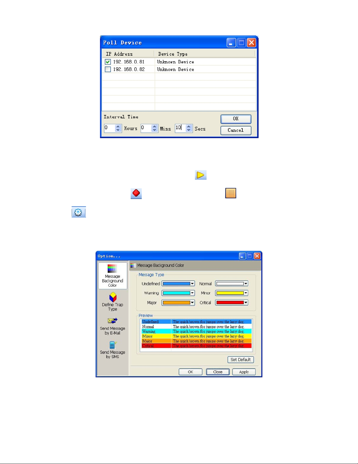
Select the IP(s) to add in polling queue. Set the polling in terval time. Click “OK” to confirm the operation.
Receive Trap
The program listens to port 162 to receive trap messages. Use the
programs are using port 162.) Use the
grid. Use the
icon to open the options window. This window allows the user to define message background colors
icon to stop the receive trap. The icon can be used to show or hide the
icon to start the receive trap. (Make sure no oth er
for different message types; define different message types; setup Email parameters; and setup SMS parameters. The
window below shows how to define message background colors.
The screen shot below shows the screen to define the trap type. (Make sure that there is different ID in the same node.)
Model OTOHP-NMS User Guide, Rev. X1 www.olsontech.com
23
Page 24
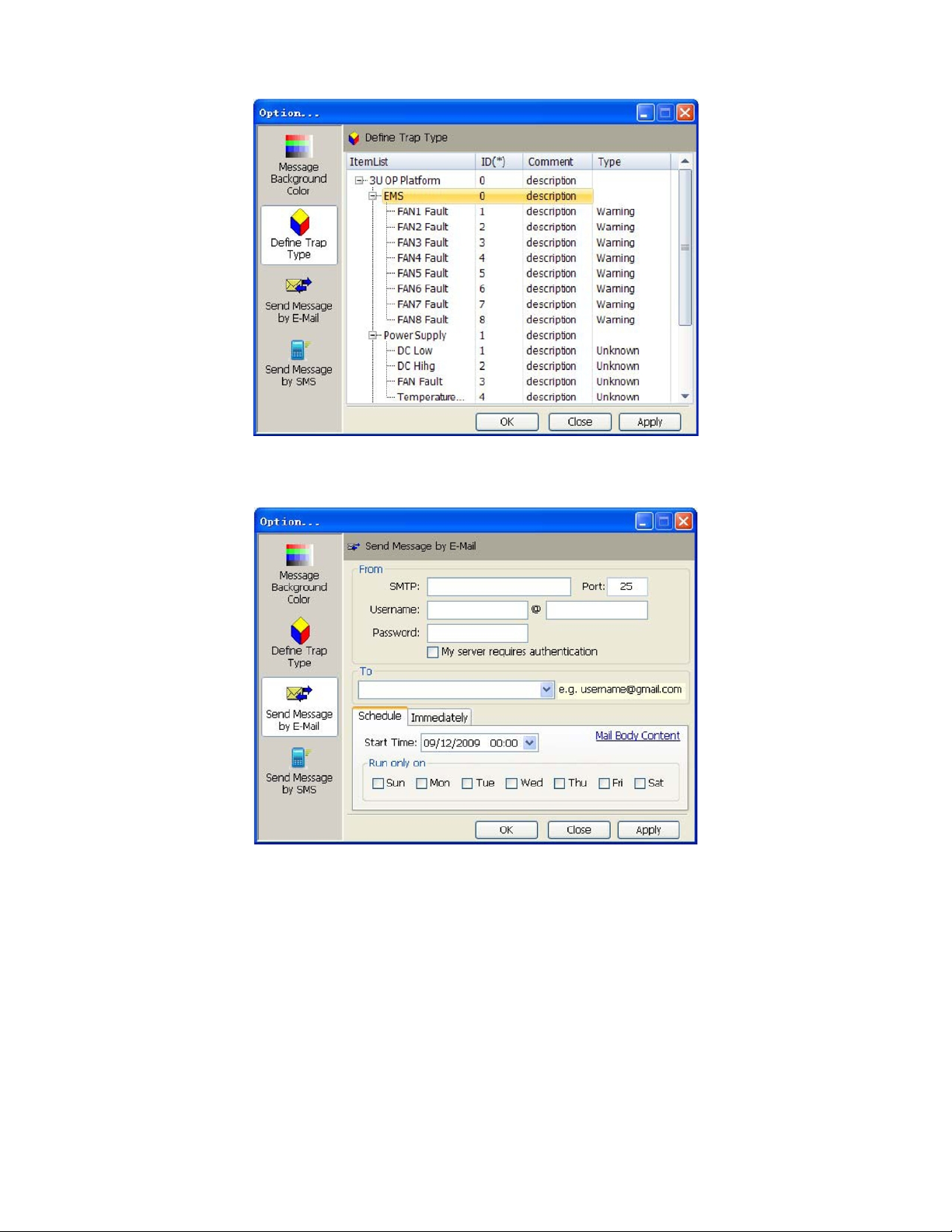
The screen below shows the parameters for setting up email messages from the system.
The screen below shows the parameters for setting up SMS messages from the system.
Model OTOHP-NMS User Guide, Rev. X1 www.olsontech.com
24
Page 25
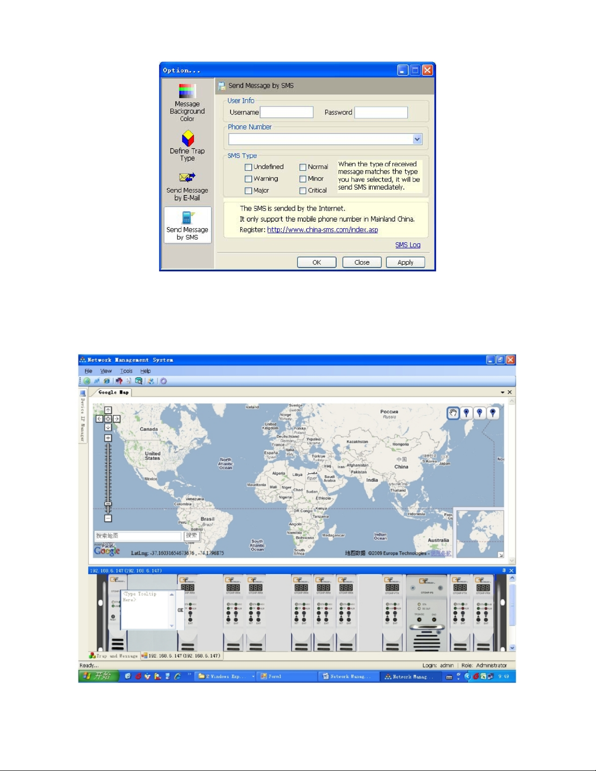
3RU SERIES DEVICE
Adding Tool Tips
Right click the device in any slot, and then add your tool tip.
Model OTOHP-NMS User Guide, Rev. X1 www.olsontech.com
25
Page 26
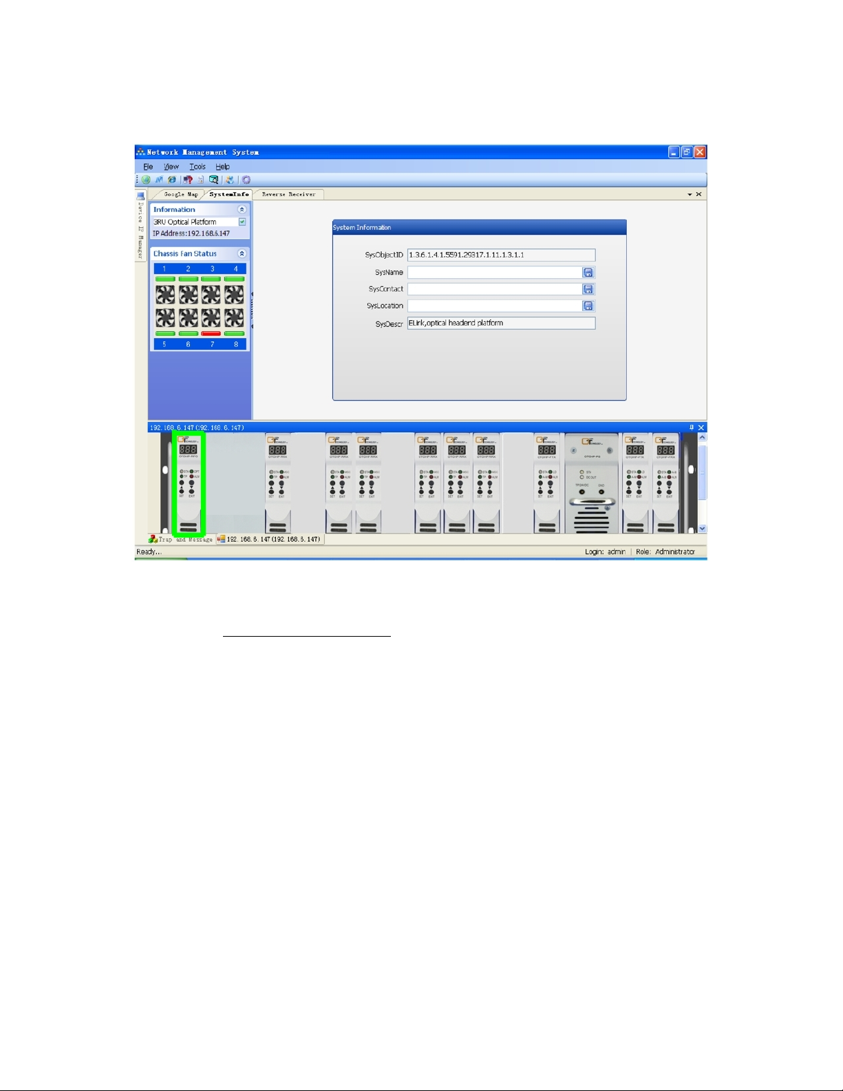
OTOHP-NMS Network Management System Module
This screen displays 3RU device information and chassis fan state.
Alarm codes are displayed in trap and message form as shown below. Administrator access is required in order to change
the system name, system contact, and system location.
Code Description
001 Fan 1 Failure
002 Fan 2 Failure
003 Fan 3 Failure
004 Fan 4 Failure
005 Fan 5 Failure
006 Fan 6 Failure
007 Fan 7 Failure
008 Fan 8 Failure
Model OTOHP-NMS User Guide, Rev. X1 www.olsontech.com
26
Page 27
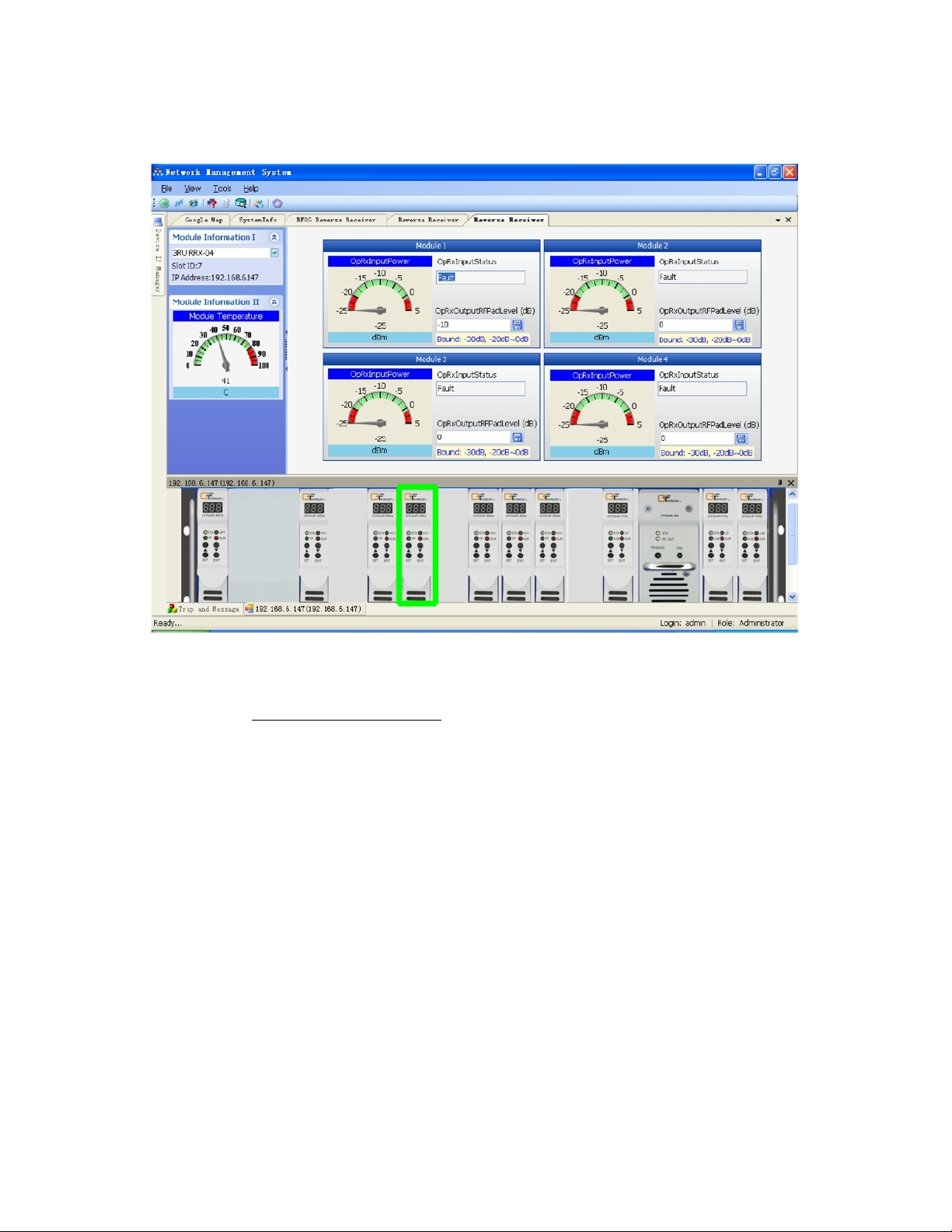
OTOHP-RRX-04 Quad Reverse Return Path Receiver Module
This screen displays the status of the OTOHP-RRX-04 module(s).
Alarm codes are displayed in trap and message form as shown below. Administrator access is required in order to change
the RF pad level.
Code Description
001 Module 1 Input Optical Power Low (less than -20dBm)
002 Module 1 Input Optical Power High (greater than 1dBm)
003 Module 2 Input Optical Power Low (less than -20dBm)
004 Module 2 Input Optical Power High (greater than 1dBm)
005 Module 3 Input Optical Power Low (less than -20dBm)
006 Module 3 Input Optical Power High (greater than 1dBm)
007 Module 4 Input Optical Power Low (less than -20dBm)
008 Module 4 Input Optical Power High (greater than 1dBm)
009 Module Temperature High (greater than 80°C)
When the value is out the range of meter, double click the meter to change scale. When the window is closed, the system
will save the new scale settings as the default.
Model OTOHP-NMS User Guide, Rev. X1 www.olsontech.com
27
Page 28
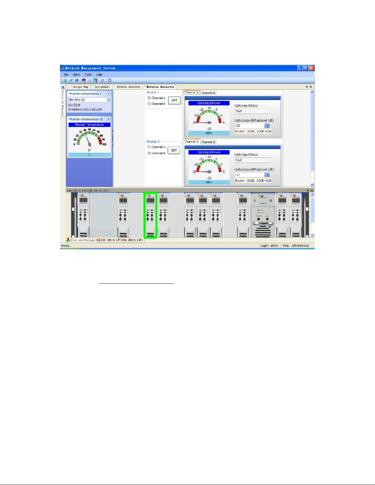
OTOHP-RRX-02 Dual Reverse Return Path Receiver Module
This screen displays the status of the OTOHP-RRX-02 module(s).
Alarm codes are displayed in trap and message form as shown below. Administrator access is required in order to change
the RF pad level.
Code Description
001 Module 1 Input Optical Power Low (less than -20dBm)
002 Module 1 Input Optical Power High (greater than 1dBm)
003 Module 2 Input Optical Power Low (less than -20dBm)
004 Module 2 Input Optical Power High (greater than 1dBm)
005 Module 3 Input Optical Power Low (less than -20dBm)
006 Module 3 Input Optical Power High (greater than 1dBm)
007 Module 4 Input Optical Power Low (less than -20dBm)
008 Module 4 Input Optical Power High (greater than 1dBm)
009 Module Temperature High (greater than 80°C)
When the value is out the range of meter, double click the meter to change scale. When the window is closed, the system
will save the new scale settings as the default.
Model OTOHP-NMS User Guide, Rev. X1 www.olsontech.com
28
Page 29
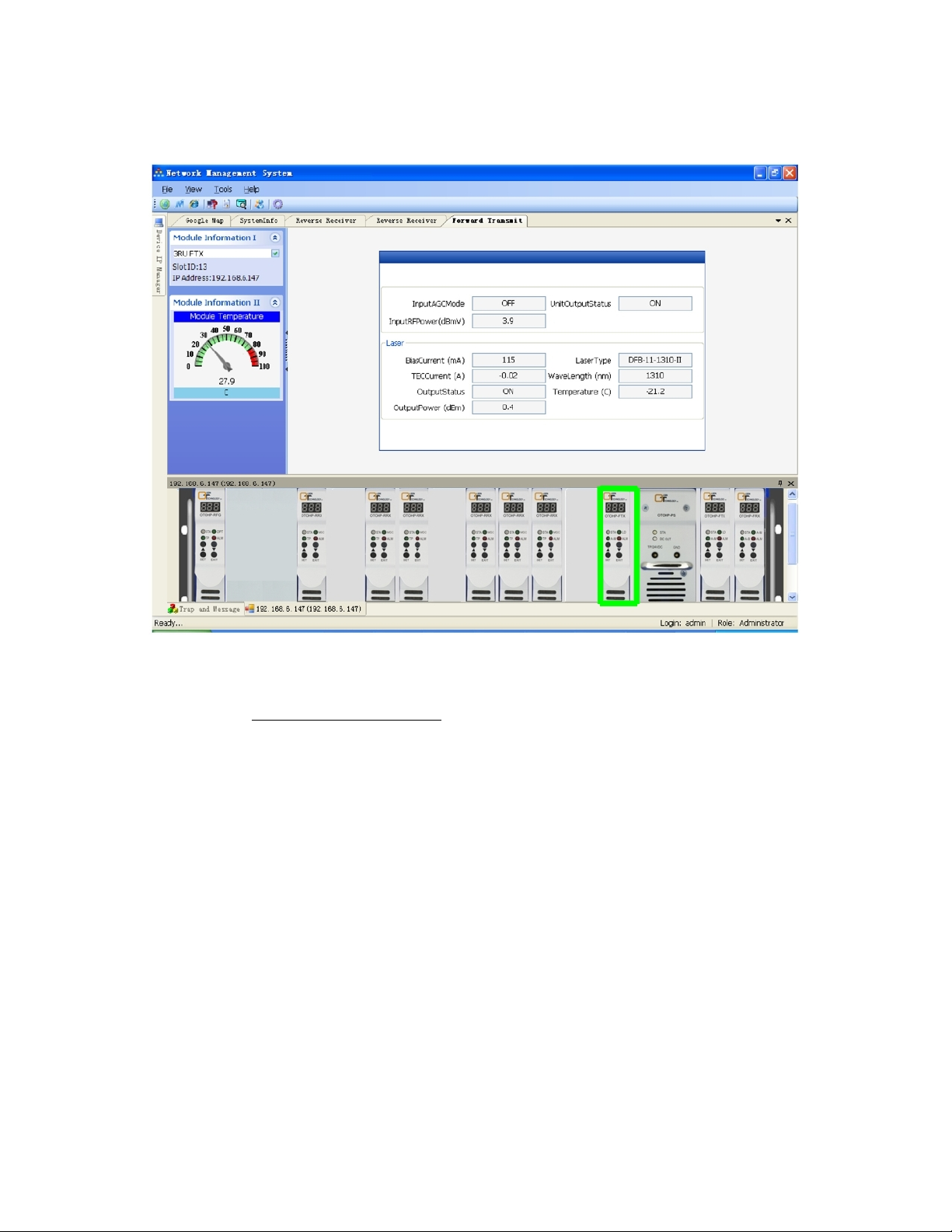
OTOHP-FTX Forward Path CATV Transmitter Module
This screen displays the status of the OTOHP-FTX module(s).
Alarm codes are displayed in trap and message form as shown below. The user is not allowed to change any of these
parameters remotely.
Code Description
001 Output Optical Power Low (less than 30% of normal)
002 Output Optical Power High (greater than 30% of normal)
003 LD Bias Current High (greater than 100mA)
004 LD Temperature High (greater than 30°C)
005 RF Input Low (less than 7dBm)
006 Module Temperature High (greater than 80°C)
007 TEC Current High (greater than 1A)
008 RF Input High (greater than 7dBm)
When the value is out the range of meter, double click the meter to change scale. When the window is closed, the system
will save the new scale settings as the default.
Model OTOHP-NMS User Guide, Rev. X1 www.olsontech.com
29
Page 30
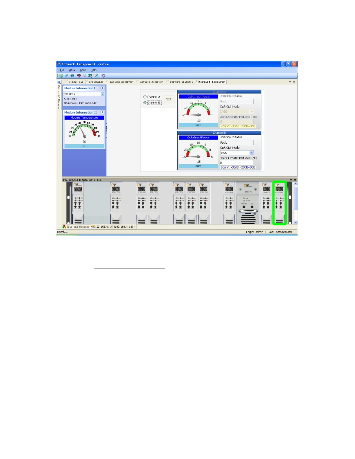
OTOHP-FRX Forward Path Receiver Module
This screen displays the status of the OTOHP-FRX module(s).
Alarm codes are displayed in trap and message form as shown below. Administrator access is required to switch channels or
change the Gain mode.
Code Description
001 Module 1 Input Optical Power Low
002 Module 1 Input Optical Power High
003 Module 2 Input Optical Power Low
004 Module 2 Input Optical Power High
005 Module Temperature High
When the value is out the range of meter, double click the meter to change scale. When the window is closed, the system
will save the new scale settings as the default.
Model OTOHP-NMS User Guide, Rev. X1 www.olsontech.com
30
Page 31
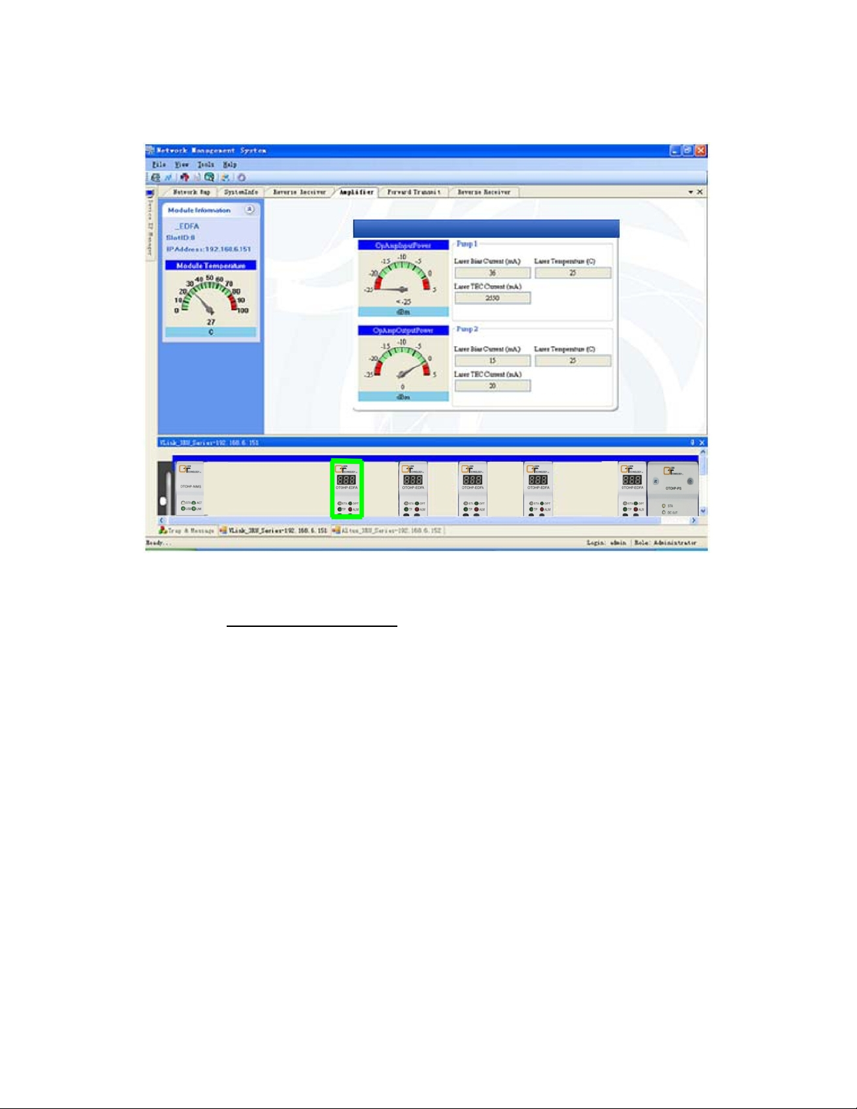
OTOHP-EDFA Module
This screen displays the status of the OTOHP-EDFA module(s).
Alarm codes are displayed in trap and message form as shown below. The user is not allowed to change any of these
parameters remotely.
Code Description
001 Input Optical Power Low
002 Input Optical Power High
003 Output Optical Power Low
004 Output Optical Power High
005 Pump-1 Drive Current High
006 Pump-2 Drive Current High
007 Pump-1 TEC Current High
008 Pump-2 TEC Current High
009 Pump-1 Temperature High
010 Pump-2 Temperature High
011 Module Temperature High
012 Communication Error
When the value is out the range of meter, double click the meter to change scale. When the window is closed, the system
will save the new scale settings as the default.
Model OTOHP-NMS User Guide, Rev. X1 www.olsontech.com
31
Page 32
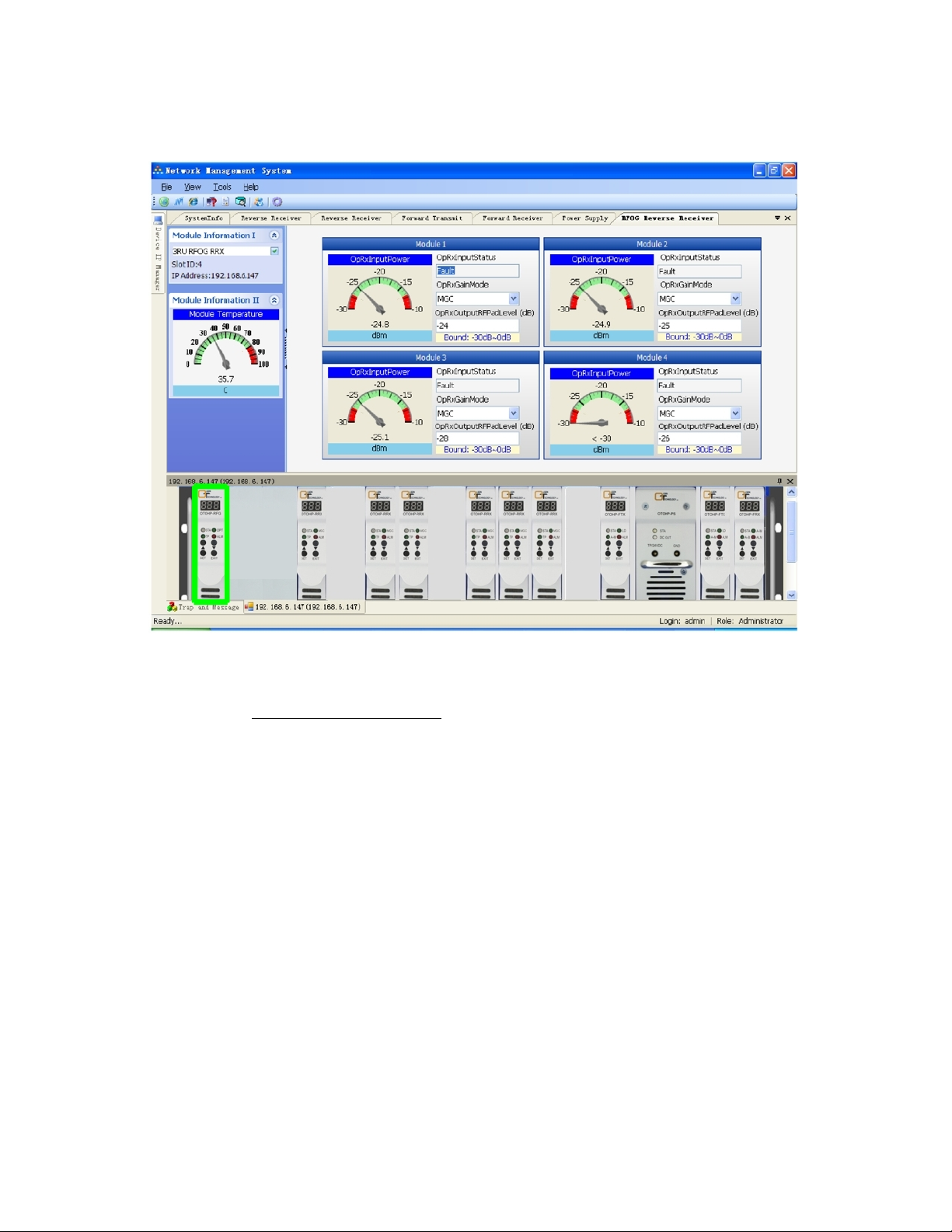
OTOHP-RFG Quad RFoG Receiver Module
This screen displays the status of the OTOHP-RFG module(s).
Alarm codes are displayed in trap and message form as shown below. Administrator access is required in order to change
the RF pad level and the Gain type (AGC/MGC).
Code Description
001 Module 1 Input Optical Power Low
002 Module 1 Input Optical Power High
003 Module 2 Input Optical Power Low
004 Module 2 Input Optical Power High
005 Module 3 Input Optical Power Low
006 Module 3 Input Optical Power High
007 Module 4 Input Optical Power Low
008 Module 4 Input Optical Power High
009 Module Temperature High
When the value is out the range of meter, double click the meter to change scale. When the window is closed, the system
will save the new scale settings as the default.
Model OTOHP-NMS User Guide, Rev. X1 www.olsontech.com
32
Page 33
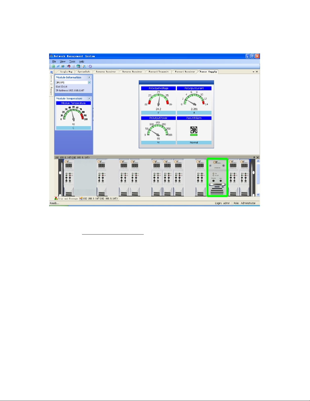
OTOHP-PS Power Supply Module
This screen displays the status of the OTOHP-PS power supply module(s).
Alarm codes are displayed in trap and message form as shown below. The user is not allowed to change any of these
parameters remotely.
Code Description
001 DC Out Low (less than 22.8V)
002 DC Out High (great than 25.2V)
003 Fan Alarm
004 Module Temperature High (great than 85°C)
When the value is out the range of meter, double click the meter to change scale. When the window is closed, the system
will save the new scale settings as the default.
Model OTOHP-NMS User Guide, Rev. X1 www.olsontech.com
33
Page 34
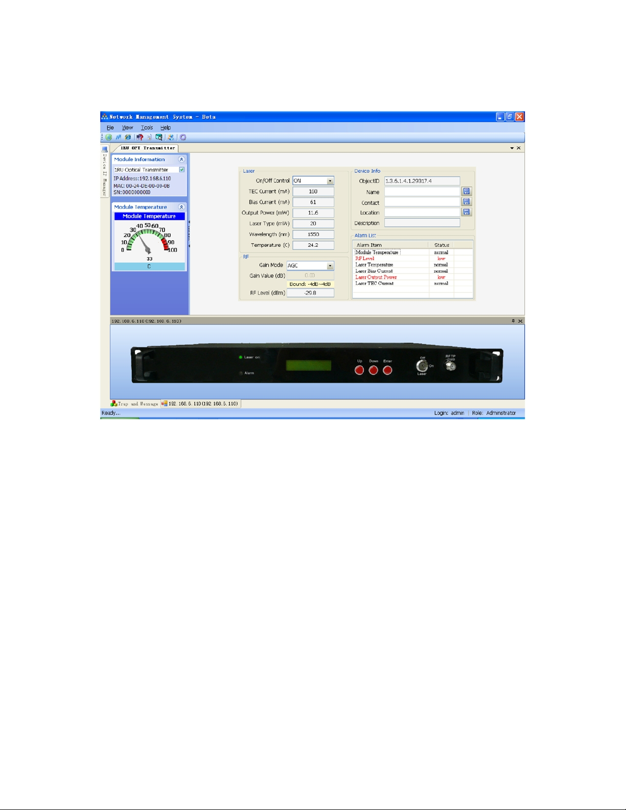
1RU Transmitter
1RU SERIES DEVICE
The laser region displays the laser parame ters ( on/off control). The RF region allows the user to set AGC/MGC control and
sets/displays the gain value. The alarm list display the list of active alarms for the device. The user may also set the device
name, contact, and device location.
Model OTOHP-NMS User Guide, Rev. X1 www.olsontech.com
34
Page 35
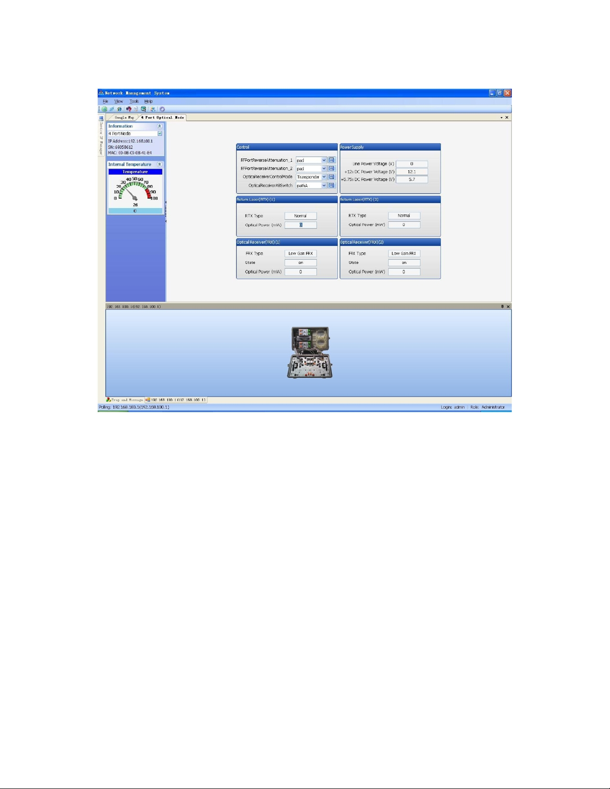
Four-Port Optical Node
Note: When the state of RTX and FRX changes to disabled, there is no 4-port optical node installed.
Model OTOHP-NMS User Guide, Rev. X1 www.olsontech.com
35
Page 36
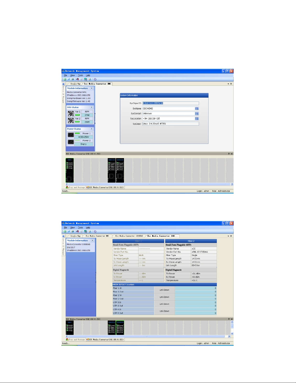
EOC MEDIA CONVERTERS
NMC
Displays the device IP address, hardware version, firmware version, fan status and RPM (revolutions per minute), and
power status.
1000EAS
Display the SFP (Small Form Pluggable) module parameters and ports RMON IN/OUT counters.
Model OTOHP-NMS User Guide, Rev. X1 www.olsontech.com
36
Page 37
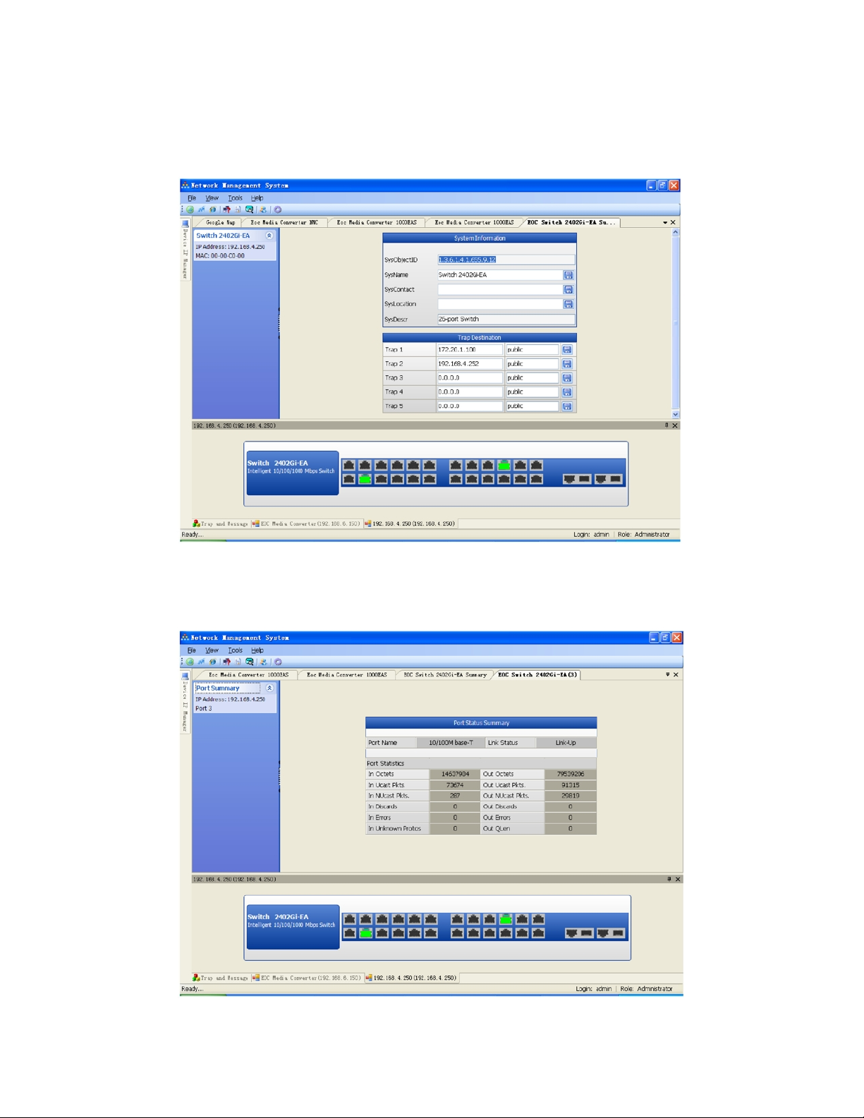
Chassis
Displays the device MAC and trap destination.
EOC SWITCH
Ports
Displays the selected port status.
Model OTOHP-NMS User Guide, Rev. X1 www.olsontech.com
37
Page 38
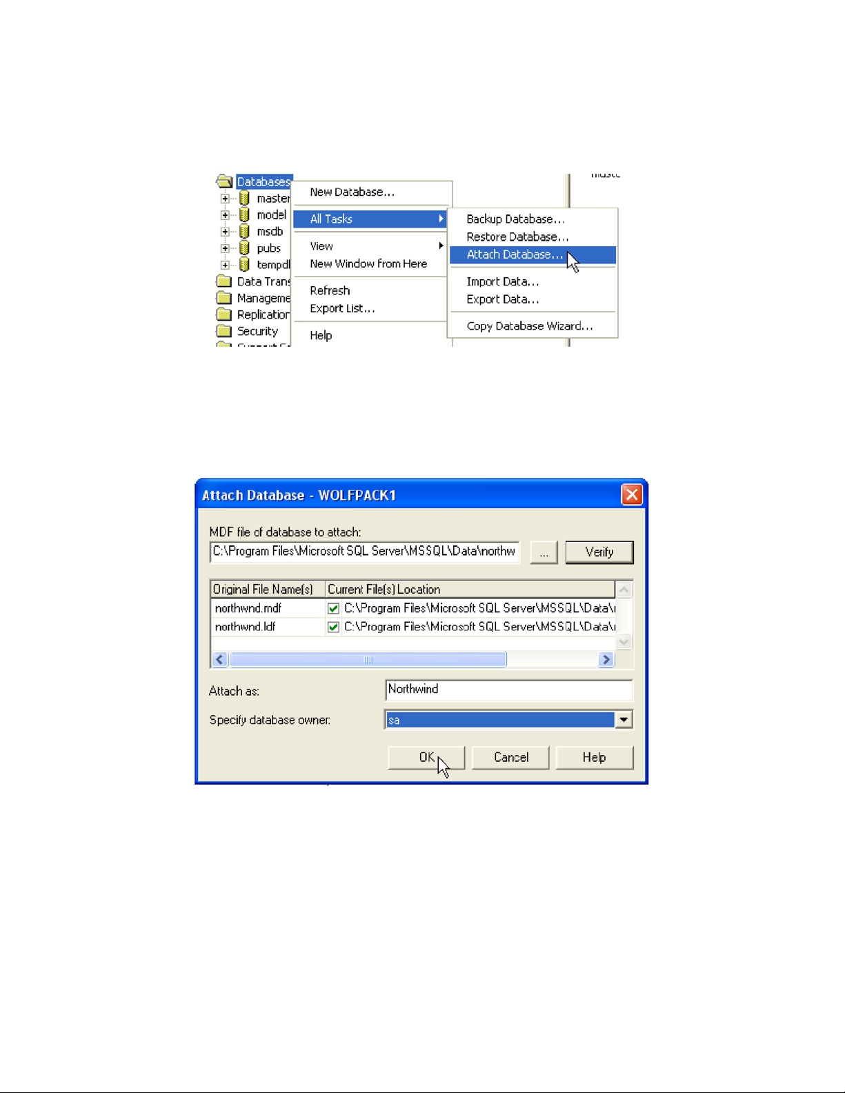
ATTACHING A DATABASE FILE TO SQL SERVER
SQL Server 2000
1) In Enterprise Manager. Right click on the database and select “All Tasks” – “Attach database.”
2) The “Attach Database” screen pops up. Hit the ellipses button to search for the .mdf (primary data file) of the
database to attach. Once selected, all files belonging to the database will appear. Choose the name of the database to
attach as, specify the database owner then click the “OK” button. You will receive a notification that the database has
been attached successfully. Click “OK” to continue.
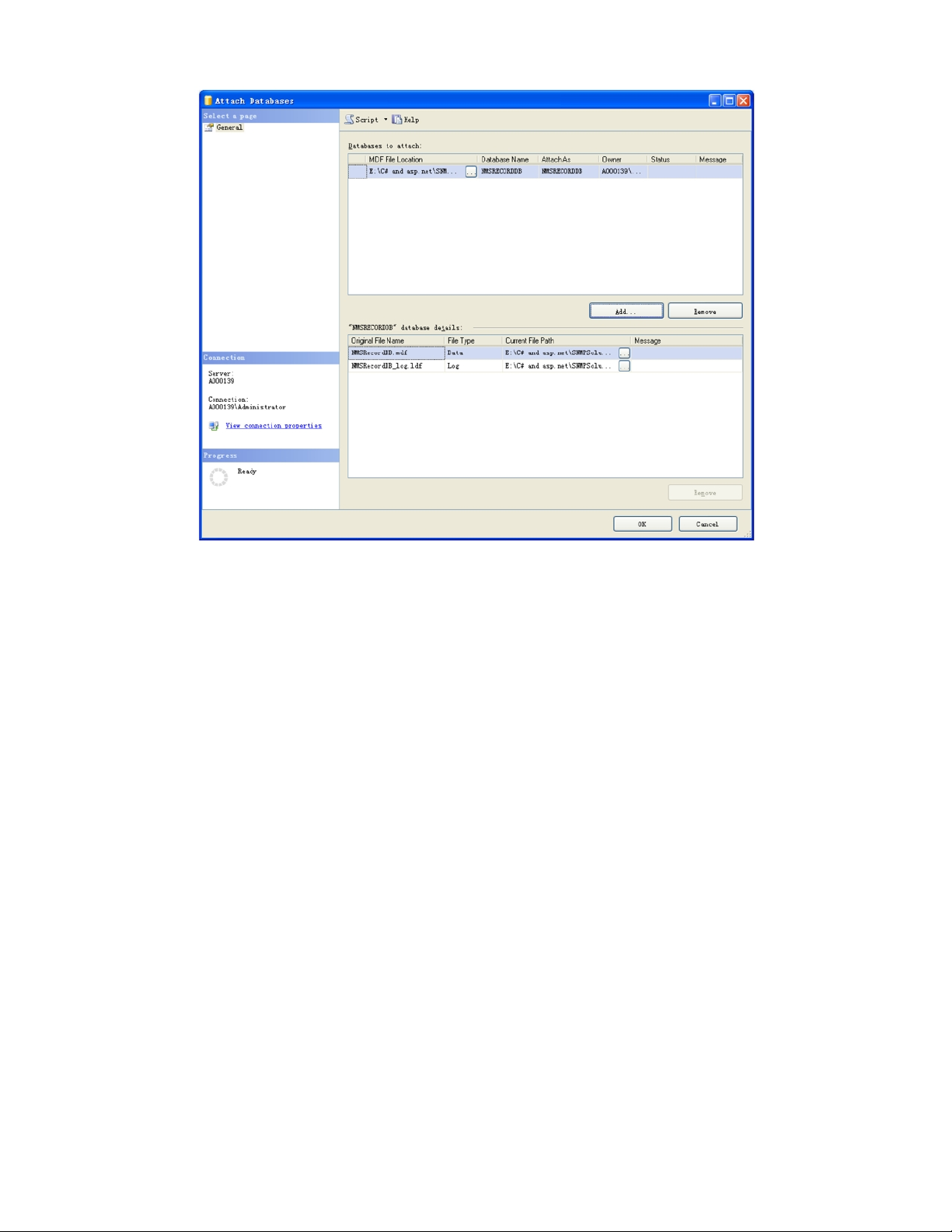
SQL Server 2005
1) Open the SQL Server Management Studio and connect to the desired server.
2) Right-click on “Databases” and select “Attach.”
3) Click the “Add” button and select the database file to be attached.
4) Click “Ok.”
Model OTOHP-NMS User Guide, Rev. X1 www.olsontech.com
38
Page 39
Model OTOHP-NMS User Guide, Rev. X1 www.olsontech.com
39
 Loading...