

Page 1
025-000643 Rev X1
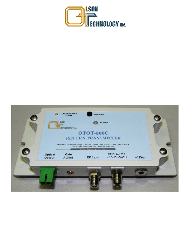
OTOT-300C
OLSON TECHNOLOGY, INC.
GENERAL PURPOSE
RETURN PATH TRANSMITTER
INSTRUCTION MANUAL
Phone: (209) 586-1022
(800) 545-1022
Fax: (209) 586-1026
E-Mail: [email protected]
www.olsontech.com
07/20/11
Page 2

SAFETY WARNINGS
LASER RADIATION
A laser transmitter emits invisible radiation that can cause permanent eye
damage. . Operate the transmitter only
with theproper opticalfiber installedin thetransmitter opticalconnector. Power to
the OTOT-300C should be turned-off or preferably, disconnected whenever the
optical connectorcover isopened and there is no installed fiber (as whenthe fiber
connector is beinginstalled orremoved from thetransmitterconnector).
The OTOT-300Cis designed forindoor use only.Directexposure to moisturemust
be avoided. Connect the AC Adapter into the OTOT-300C before plugging the
adapter into thewall.
AVOID DIRECT EXPOSURE TO BEAM
NEVER
USE ANY OPTICAL INSTRUMENT TO VIEW THE OUTPUT OF THE
LASER TRANSMITTER. “OPTICAL INSTRUMENT” INCLUDES MAGNIFYING
GLASSES, ETC.
NEVER
LOOK INTO THE OUTPUT OF THE LASER TRANSMITTER
NEVER
LOOK INTO THE OUTPUT OF A FIBER CONNECTED TO A LASER
TRANSMITTER.
NEVER
LOOK INTO OR USE ANY OPTICAL INSTRUMENT TO VIEW THE
DISTANT END OF AFIBER THAT MAY BE CONNECTED DIRECTLY OR VIA AN
OPTICAL SPLITTER, TO A TRANSMITTER THAT MAY BE OPERATING. THIS
SPECIFICALLY APPLIES TO FIBERS THAT ARE TO BE CONNECTED TO
RECEIVERS OR OTHER DEVICES AT ANY DISTANCE FROM THE LASER
TRANSMITTER.
SHOCK HAZARD
Page 3

INTRODUCTION
The Olson Technology, Inc. Model OTOT-300C is a General Purpose CATV
Return Path Transmitter. It offers wide analog RF bandwidth of 5-300MHz. It is
available with a variety of laser options including 1310nm DFB, 1550nm DFB and
CWDM wavelengths at optical output powers ranging from1mW (0dBm) to 3mW
(+5dBm).
The OTOT-300C offers a low-cost alternative to digital return path
hardware. It is compatible with most analog RF return path optical receivers.The
Olson Technology, Inc. OTOR-300TripleReturn Path Receiver is anideal mate to
the OTOT-300C.
The OTOT-300C is built in a rugged castAluminum housingand
is powered from+12 Voltsto +16VoltsDC. (Power supply orderedseparately.)
The OTOT-300C features an RF Drive test point that will yield +10dBmV per
channel with a standard 5-42MHz CATV returnload. Theunit alsohas a 20dB RF
gain adjustment, which allows the unit to deal with non-standard CATV return
loads. The unit has a green LED to provide a positive indication that the unit is
powered and aDC testpoint that indicatesthe optical output power (1Volt/mW).
INSTALLATION/ ENVIRONMENTALCONSIDERATIONS
The OTOT-300C is specified to operate from -10°C to +55°C. It usually will not
require an air-conditioned environment. It should be mounted in an adequately
ventilated area.Like any other electronic equipment, it willprobably have a longer
life spanif it isnot operated atthe upper limitof the temperature range. Installation
in wetareas or areas of extremely high humidity should be avoided. Dirty or dusty
areas should be avoided if possible. The OTOT-300C should not be installed in
areas that areaccessible tochildren.
The OTOT-300C may be installed and operated in any position on a flat surface.
The unit has two slots in the bottom flange to accommodate mounting hardware.
The unit should be mounted by sliding under one screw and then installing and
tightening the other screw. If mounting requires a wood screw, use #6 or #8
(maximum) pan-head sheet metal screws. These are commonly available at
hardware stores. If mounting with a machine screw (to tapped holes), use 6-32
pan-head screws.
Figure 1 showsthe keydimensions of theOTOT-300C.
Page 4
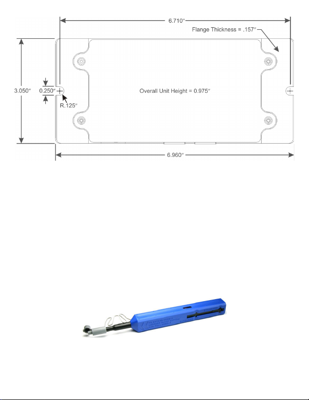
Figure 1 - OTOT-300C Key Dimensions
OPTICAL CONNECTORS AND CLEANING
The standard optical connector is an SC/APC. In order to use an FC/APC
connectors, you must order a conversion kit, OTLL-SCFCKIT. The standard
optical connectorlocation is onthe same side as theRF connector. The fiberends
can be damaged by the insertion of contaminated connectors. Some types of
customer damage to connectors are not covered under warranty. Fiber
connectors should never be left uncovered. Pre-packaged alcohol wipes are a
convenient means of cleaning optical connectors. Clean alcohol and lint free
wipes, such asKim-Wipe type34155, or swabsmayalso be used.
More sophisticated fiber optic connector cleaners, such as the Senko
SmartCleaner (SCK-SC-250) are very effective for cleaning external and internal
fiber optic connectors.
Figure 2 - Senko SmartCleaner
Page 5

OPERATIONAL SETUP – RETURN PATH TRANSMITTER
First mount theOTOT-300C in asuitablelocation.
Next, be certain that electrical power is NOT applied to the transmitter. The green
Power LED should be dark. Then clean and attach the optical fiber. Electrical
power may nowbe applied.
The OTOT-300C transmitter is a key component in a CATV Return Path optical
link. Proper RF input level to the OTOT-300C is critical to good performance. The
RF input level to any optical transmitter is dependent on the number of channels
being transmitted. As the numberofcarried channels islowered,the RF inputlevel
to thetransmitter canbe raised. This results in increased RF levels atthe receiver
and improves NPR. Links should be designed and transmitters should be set up
using values thatrepresent themaximum number ofchannelslikely to be carried.
For a normal 5-42MHz return path load, the RF Input Levelshould be adjusted so
that the signalat theRF Test Point is+10dBmVper channel.
Page 6
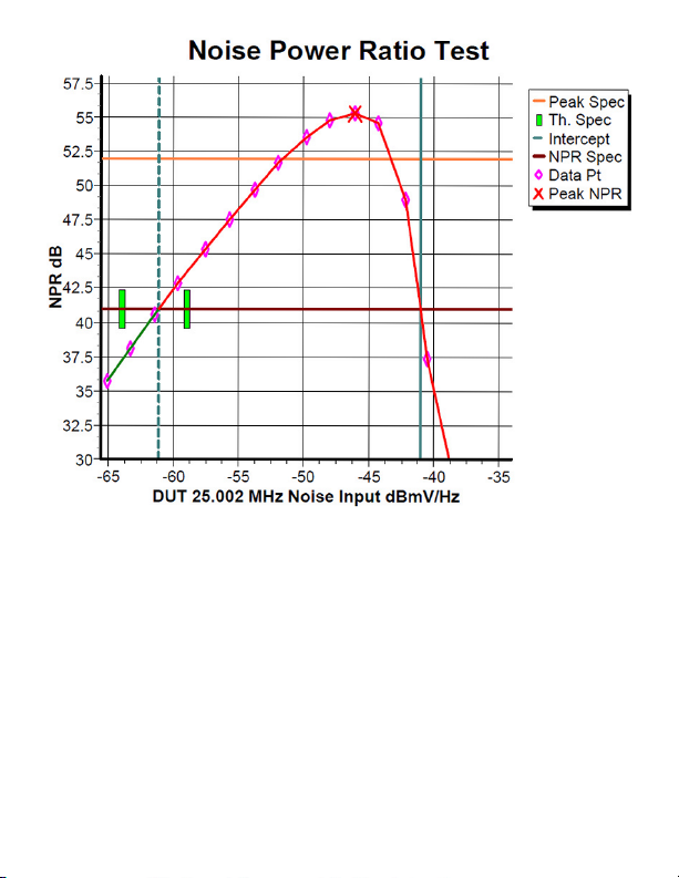
Figure 3 - Typical NPR Performance
TEST POINTS and ADJUSTMENTS
The OTOT-300C features an RF Drive test point that will yield +10dBmV per
channel when theRFinput level isoptimumwith a standard5-42MHzCATVreturn
load. Connect the RF input to the transmitter and adjust the level until +10dBmV
per channel is measured on the test point. Figure 2 shows typical NPR
performance with greaterthan 18dBof usable dynamicrangeabove 41dB NPR.
The unit also has a 20dB RF gain adjustment, which allows the unit to deal with
non-standard CATV return loads. The unit has a green LED to provide a positive
indication that the unit is powered and a DC test point that indicates the optical
output power (1Volt/mW).
Page 7
RF Output & Performance Characteristics
Min Typ Max Units
Frequency Range 5 300 MHz
Pass Band Flatness -1 +1 dB
RF Test Point (35MHz Load) +10 dBmV/Ch
RF Test Point Flatness -1 +1 dB
Impedance (F Connector) 75 Ohms
RF Adjustment Range 20 dB
Return Loss 15 dB
DFB 41dB NPR Threshold * -60
DFB & CWDM NPR Range 15 18 dB
* RF Adjustment is centered.
Physical Characteristics
Min Typ Max Units
Weight 12 oz.
340 g
Dimensions (H x W x L) 3.05 x 6.96 x 0.975 in.
7.75 x 17.7 x 2.48 cm
dBmV/Hz
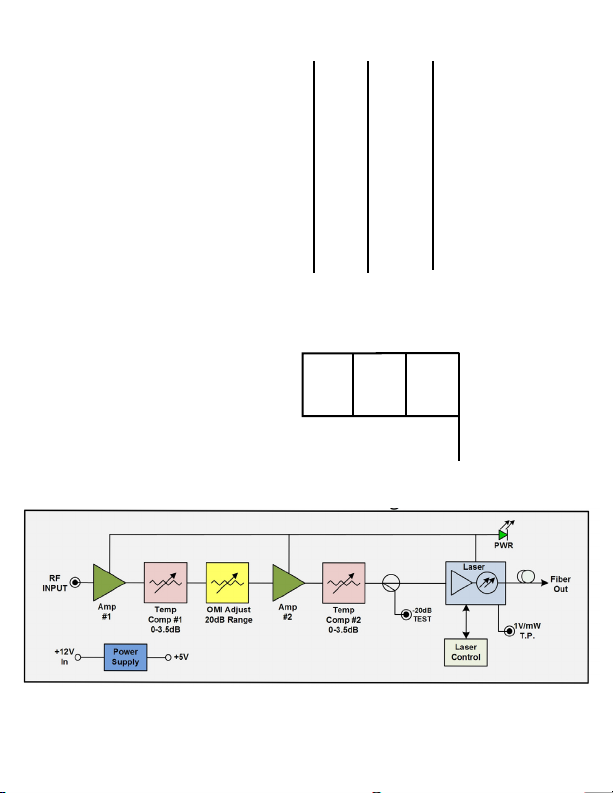
Figure 4 - OTOT-300C Block Diagram
Page 8

Optical Characteristics (with SM 9/125µm SM Fiber)
Min Typ Max Units
Operating Wavelength (1310) 1290 1310 1330 nm
Operating Wavelength (1550) 1530 1550 1570 nm
Operating Wavelength (CWDM) -3 ITU +3 nm
Optical Power -0.5 Rated +0.5 mW
Optical Return Loss 55 dB
Optical Connector (Std.) SC/APC
Optical Connector (Option) FC/APC
Notes: All measurements at +25°C
Ordering Information
Transmitter Options
Model OTOT-304C-SA/1 Tx, 1310nm DFB, 1mW, SC/APC
Model OTOT-304C-SA/2 Tx, 1310nm DFB, 2mW, SC/APC
Model OTOT-304C-SA/3 Tx, 1310nm DFB, 3mW, SC/APC
Model OTOT-305C-SA Tx, 1550nm DFB, 2mW, SC/APC
Model OTOT-347C-SA Tx, CWDM, 1470nm, 2mW, SC/APC
Model OTOT-349C-SA Tx, CWDM, 1490nm, 2mW, SC/APC
Model OTOT-351C-SA Tx, CWDM, 1510nm, 2mW, SC/APC
Model OTOT-353C-SA Tx, CWDM, 1530nm, 2mW, SC/APC
Model OTOT-355C-SA Tx, CWDM, 1550nm, 2mW, SC/APC
Model OTOT-357C-SA Tx, CWDM, 1570nm, 2mW, SC/APC
Model OTOT-359C-SA Tx, CWDM, 1590nm, 2mW, SC/APC
Model OTOT-361C-SA Tx, CWDM, 1610nm, 2mW, SC/APC
Power Supply
Model OTPS-12A Universal AC, +12V, 1.5A, 2.1mm/5.5mm DC plug
Accessories
Model OTLL-SCFCKIT Optical Connector Adapter Kit, SC/APC to FC/APC
 Loading...