

Page 1

MODEL OTM-4870-P AL-B/G
FREQUENCY AGILE 870MHz
P AL B/G TELEVISION MODULA T OR
USERS MANUAL
Phone:
E-Mail: [email protected]
025-000337 Rev . x1 10/30/02
(209) 586-1022
(800) 545-1022
Fax:
(209) 586-1026
www.olsontech.com
Page 2
RF
Frequency Range...................
RF Output Level....................
Accuracy/Stability................
Spurious Output....................
Out-of-Band C/N Ratio..........
Phase Noise...........................
Audio/Video Ratio.................
VIDEO
Baseband Input Level............
Video Performance................
Frequency Response..............
Video AGC............................
AUDIO
Baseband Input Level............
Intercarrier Stability...............
Audio Performance................
Frequency Response..............
Pre-Emphasis........................
Audio Subcarrier Input..........
48.25MHz to 865.25MHz
Selectable by front panel
touchbuttons by channel or
frequency in 12.5KHz increments.
+61dBmV typical
±5KHZ
>60dBc (typical)
>80dB
>90dBc @ 10KHz offset
-12dB to -21dB below video
carrier level
.5 to 1.5 volts p-p (75Ω)
1V p-p @ 87.5% modulation
Differential Gain <3%
Differential Phase <2°
+1dB, 30Hz to 4.8MHz
On/Off front panel control
-10 to +10dBm, 600 Ω
balanced, Hi Z unbalanced
+1KHz
2% maximum THD (1%
typical)
50Hz to 15KHz, ±1dB
75 ìs NTSC, 50 ì s P AL, defeated
by internal jumper for BTSC
and SAP compatibility
+25dBmV to +45dBmV
@75 Ω
AUX. IF INPUT
Four Modes of Control.............
EXTERNAL FEATURES
Front Panel Controls................
Front Panel LED’s...................
Rear Panel Connectors.............
GENERAL
Power Supply...........................
Physical Size............................
Weight......................................
Power Consumption.................
Operating Temperature............
Loss of video to modulator, rear
panel closure screws for EAS
compatibility
Video/Audio modulation levels,
Audio to Video carrier ratio, RF
output level, LCD contrast
control, Push button menu
controls
RF on, AUX IF in use, Synthesizer unlocked, Video/Audio
over modulation
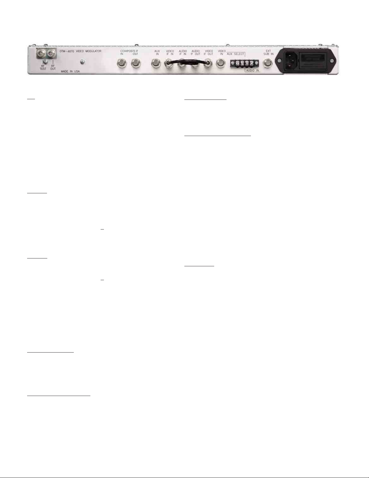
T ype “F” connectors for RF
output, RF test point, AUX IF
input, Video baseband input,
Video and Audio IF inputs/
outputs. Composite IF input/
output and Audio subcarrier.
Screw terminals for contact
closure/audio baseband
Universal 90 VAC to 240 VAC,
50 to 60Hz with IEC 320 power
connector
1.75” H x 19” W x 10” D
9 lbs.
24 Watts
0° C to 50° C
DUAL IF LOOPS
Video IF................................
Audio IF...............................
COMPOSITE IF LOOP
Video IF................................
Audio IF...............................
025-000337 Rev . x1
+36dBmV @ 38.9MHz
(typical)
Adjustable -12dB to -21dB
relative to video carrier
+18dBmV @ 38.9MHz
(typical)
Adjustable -12 to -21dB
relative to video carrier
Page 2
Page 3

OTM-4870-PAL-B/G
FREQUENCY AGILE 870MHz
P AL B/G TELEVISION MODULA T OR
1) INTRODUCTION
The Olson T echnology OTM-4870 is a frequency agile, P A L B/G television modulator . This microprocessor-controlled unit
is capable of operation on any frequency from 48MHz to 870MHz and output frequency selection is possible in 0.0125MHz
increments. Output frequencies may be selected in MHz or by channel designation.
An RF output level of +60dBmV (minimum) is possible over the operating frequency range of the OTM-4870.
SAW filtering and Olson Technology system design factors insure an out-of-band carrier-to-noise ratio greater than 80dB.
This allows unlimited numbers of these units to be combined.
The OTM-4870 has many advanced features including a menu/button control system, front panel display of channel and
channel ID text, a manual or loss-of-video controlled auxiliary I.F. input with AGC, selectable video AGC, external audio
subcarrier input, configurable audio input, dual IF loops, composite IF loop, BTSC compatibility and more.
The OTM-4870 up-converter section is a high performance tuner with excellent phase noise and frequency response that
exceeds DOCSIS and CMTS specifications.
2) CONTROL OF THE OTM-4870-P AL-B/G
A.) FRONT PANEL ADJUSTMENTS:
Video and audio modulation levels, video-to-audio carrier ratio, and the RF output level are adjustable by means
of slotted controls accessible through the front panel. There is also a control for the LCD panel contrast which
should be adjusted for proper viewing once the unit is installed.
See section 4 of this manual for more information on these adjustments.
B.) FRONT PANEL MENU ITEM CONTROLS:
Most features of the OTM-4870 are configurable from the front panel by means of the menu/button system which
includes an LCD panel and 5 buttons. The LCD panel displays the menu(s) and the currently-selected configuration or value.
The “UP”, “DOWN”, “LEFT”, and “RIGHT” buttons are used to move between menus, to select configurations,
and to change values. All items except tuning mode and channel number/frequency will instantly change to
match the display. A new tuning mode or channel/frequency takes effect only when you press the “ENTER”
button. To make other changes permanent, press the “ENTER” button.
Note that when changing the output frequency, the unit’s digital synthesizer may become unlocked momentarily
resulting in operation on an undesired frequency until it re-locks. The OTM-4870 will turn its RF output off
anytime the unit is in an unlocked state, thus preventing unwanted interference when changing channels.
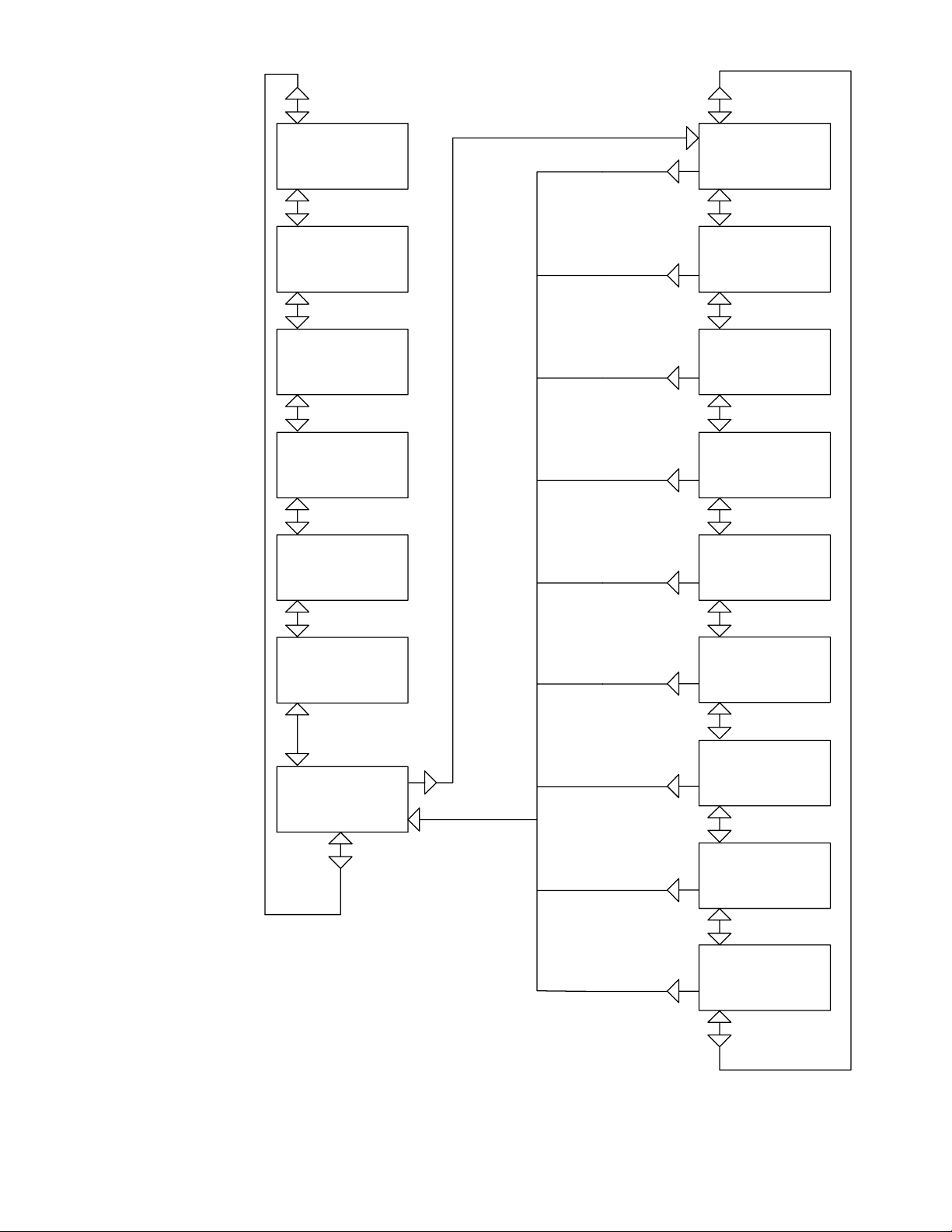
As illustrated on page 5 below, there are two menu trees; the main menu tree (on the left) and the sub-menu tree
(on the right). The arrows indicate which buttons to press to move around the menus. Review each menu and the
information below to become familiar with the various functions.
Note
DOCSIS = Data over cable service interface specification
CMTS = Cable modem termination system
025-000337 Rev . x1
Page 3
Page 4

C.) CHANGING MENU ITEMS:
T o change a function or value, select the menu containing the item to change using the “UP”, “DOWN”, “RIGHT”,
and “LEFT” buttons. After selecting the correct menu, press the “RIGHT” button to change a menu item. If part
or all of the bottom row starts flashing, you can change that item.
If the entire bottom row flashes (most items), press the “UP” or “DOWN” button to change it. These buttons have
auto-repeat. For tuning or channel ID (NAME) values, only one character in the bottom row will flash. The
“LEFT” and “RIGHT” buttons select the position to change and the “UP” and “DOWN” buttons change the
value.
When you are through with the change (or if there is no change), pressing the “ENTER” button will enable the
displayed parameter or value, the change mode is exited, and the display will stop flashing. If you do not press the
“ENTER” key, the parameter will return to the original value after a time-out of about 15 seconds.
3) SOME MENU-SPECIFIC INFORMATION
A.) Display of NAME and TUNING:
This is the normal (default) display and is the menu shown as the top left menu on page 5 of this manual. You can
not make any change from this menu. The NAME is programmable from the NAME menu and the tuning is
programmable from the TUNING menu. The display will return to this default after about 30 seconds of button
inactivity
If the programmed TUNING MODE is CHAN, the display will be the channel number. If the programmed
TUNING MODE is FREQ, the display will be the frequency in MHz.
Note that if the TUNING MODE is changed from CHAN to FREQ, the LCD will display the frequency of the
previously-selected channel.
B.) IF INPUT:
This indicates the preferred choice of the normal IF source. A rear panel input or an automatic transfer could
switch to the AUX IF input.
C.) CHANNEL PLAN:
The CHANNEL PLAN determines the OTM-4870 output frequency for a selected channel number. Tables at the
end of this manual list these values.
D.) NAME:
This menu allows you to program the NAME that appears at the top of the normal (default) display. Upper case
and lower case letters as well as numbers and various symbols are available for use.
E.) COMMAND MODE, BAUD RATE, and ADDRESS:
These functions are not used with the OTM-4870.
025-000337 Rev . x1
Page 4
Page 5
Default display of name
and tuning. Comes here
after 30 sec inactive. No
right arrow.
CSPAN
Ch 101
Display of tuning and
mode. Right arrow
changes tuning.
Tune Std.
Ch 101
or
Tune
743.2625
Display of RF output
status. Right arrow to
turn on/off.
Display of V ideo AGC
status. Right arrow to
change.
Display of IF input
preference. Right arrow
to change. Source will
stay at AUX if rear aux
input is grounded.
Display of automatic
transfer status. Right
arrow to change. If AUTO
then IF source will transfer to
AUX when video is absent.
Display of command mode. If
command mode is REMOTE,
must change it here to local
before making any local
changes. Right arrow to change.
If no remore is installed, mode is
always LOCAL.
Sub-menu entry point. Right
arrrow to enter sub-menu
RF Out
ON
OFF
VideoAGC
ON
OFF
IF In
INT
AUX
AUX Xfer
OFF
AUTO
Cmd Mode
LOCAL
REMOTE
Sub Menu
-->>
Display of tuning mode.
Right arrow to change.
Display of channel plan.
Right arrow to change.
Display of name. Right
arrow to change.
Display of Audio Subcarrier
source. Right arrow to change.
Display of Baud rate. Right
arrow to change.
Display of model name.
Read only.
TuneMode
FREQ
CHAN
ChanPlan
STD
HRC
IRC
EIA
Name
CSPAN
Audio Sub
INT
EXT
BaudRate
38,400 - 19,200 - 9,600
4,800 - 2,400 - 1,200 - 600
300
OTM-4870
NTSC
*
Revision.
Read only.
Rev ZZZZ
04/04/99
NOTE: Arrows indicate which keys to press
Display of OT 5 digit address.
Normally read only.
Address
9900
*
to move through menus.
* = Not used on OTM-4870-P AL-B/G
025-000337 Rev . x1 Page 5
Page 6
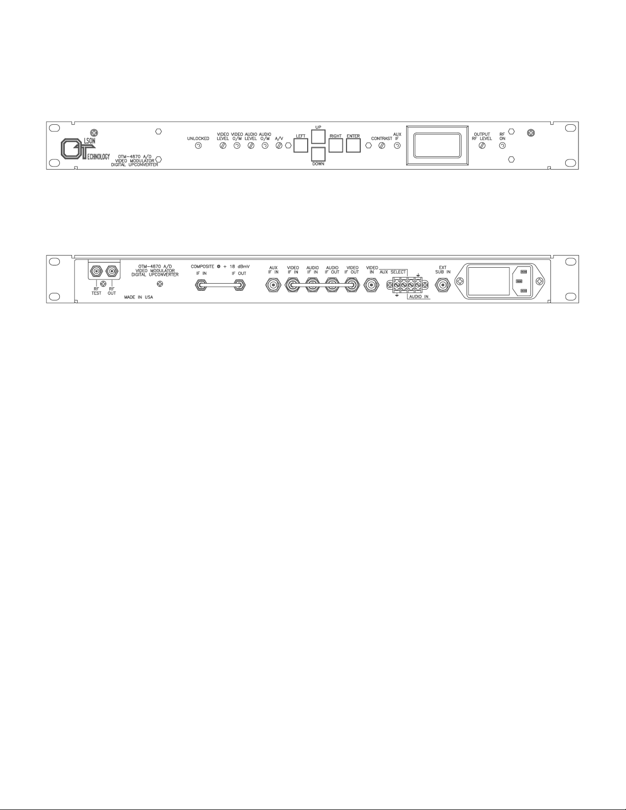
OTM-4870-P AL-B/G Front Panel
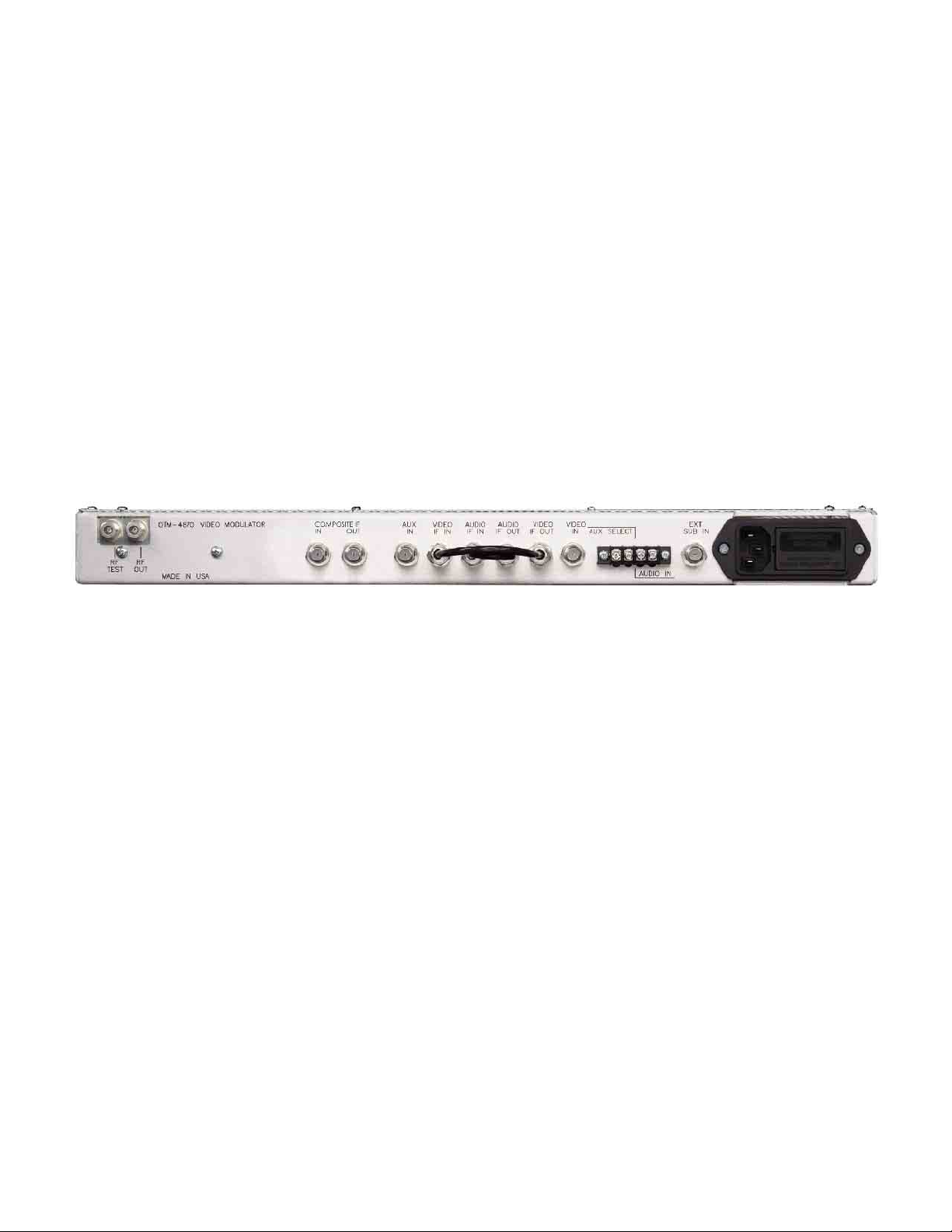
OTM-4870-P AL-B/G Rear Panel
025-000337 Rev . x1
Page 6
Page 7
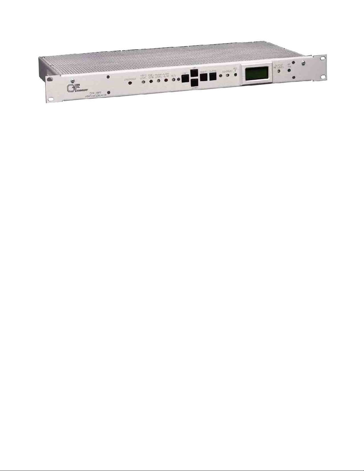
4) FRONT PANEL CONTROLS AND INDICATORS
OTM-4870-P AL-B/G FRONT P ANEL
REMOTE
The remote control feature is not available on the OTM-4870-P AL-B/G
UNLOCKED
This LED, when on, indicates that one of the digital synthesizers is not locked. This condition will result in
shutdown of the RF output as long as the condition exists. Note that this LED will usually flash on momentarily when changing a channel or frequency. This momentary shutdown of the output prevents undesired
interference to other channels if the OTM-4870-P AL-B/G is connected to a system or network when its channel is
changed.
VIDEO LEVEL
This control adjusts the video depth-of-modulation. Choose a bright scene (commercials are usually excellent)
and set it carefully while observing the VIDEO O/M LED. This control should be advanced to a point JUST
SHORT of where the VIDEO O/M LED flashes-on.
VIDEO O/M
This LED, when on, indicates a depth-of-modulation greater than 87-1/2%. It should never be on continuously
but might be on for short periods during bright scenes. See VIDEO LEVEL above.
This LED will stay on for several seconds when power is first applied to the OTM-4870-P AL-B/G.
AUDIO LEVEL
This control adjusts the audio deviation of the OTM-4870-P AL-B/G. Choose program material that is of high
average volume when setting this control and adjust it so the AUDIO O/M LED just blinks-on during program
audio level peaks.
AUDIO O/M
This LED, when on, indicates that the peak deviation of the OTM-4870-P AL-B/G is at ±50KHz. It should only
flash-on occasionally during normal operation. See AUDIO LEVEL, above.
A/V
This control adjusts the aural carrier level relative to the video carrier level. It is typically adjusted for an A/V
ratio of 15-17dB.
LEFT, RIGHT, UP, DOWN, ENTER
These buttons are used in selecting and changing menu items as displayed on the LCD panel.
CONTRAST
025-000337 Rev . x1
This control adjusts the LCD panel contrast. Adjust it for best display legibility when the OTM-4870-PAL-B/G is
placed in operation.
Page 7
Page 8
AUX IF
This LED, when on, indicates that the current IF source is the AUX input at the rear panel.
LCD DISPLAY PANEL
This displays menu and status information.
OUTPUT RF LEVEL
This control is used to set the RF output level. If the OTM-4870-P AL-B/G is feeding a system or network with
many channels, it is suggested that it be operated at an output level of +55dBmV minimum to prevent
degradation of the C/N ratio of that channel. If lower output levels are required, place an in-line attenuator at the
RF output.
Note that the OTM-4870-P AL-B/G may be capable of output levels greater than +60dBmV on some channels. The
specifications for spurious performance, etc. are based on a maximum operating level of +60dBmV. This unit may
not meet its full specification if operated at greater that +60dBmV out.
RF ON
This LED indicates the output RF status.
5) REAR PANEL CONNECTIONS
RF TEST
RF OUT
IF IN
IF OUT
AUX IN
OTM-4870-P AL-B/G REAR P ANEL
This output is approximately 20dB below the main RF output and may be used for monitoring or test.
This output is (typically) +61.0dBmV. Over the frequency range of 48.250 to 865.250MHz
This is composite IF input at approximately +18dBmV with 44MHz center frequency and 6MHz bandwidth
feeding the output tuner. In normally configured applications, this input is usually connected to composite IF
out. The OTM-4870 is shipped from the factory with this jumper in place.
This is the composite IF source for the analog TV modulator, after the saw filter, with video carrier at
+18dBmV at 38.9MHz. Audio is 33.4MHz and is 12 to 18dB lower than video. In normally configured
applications this output is usually connected to composite IF IN. The OTM-4870-PAL-B/G is shipped from the
factory with this jumper in place.
This is the AUX IF input. This input is before the SAW IF section and normally expects an IF input level of
+38 dBmV. It has AGC which will allow levels to vary as much as ±5dB while holding the RF output level
constant.
This input may be enabled by shorting the AUX SELECT terminals on the rear panel, by front panel control,
or by loss of video.
025-000337 Rev . x1
Page 8
Page 9

VIDEO IF IN
This is the video IF input to the SAW filter / output converter section. The AUX IF switch is AFTER this
input. The video IF level at this point should be +38 dBmV.
In normally-configured applications this input is usually connected to the VIDEO IF OUT connector. The
OTM-4870-P AL-B/G is shipped from the factory with this jumper in place.
AUDIO IF IN
This is the aural IF input to the SAW filter / output converter section. The AUX IF switch is AFTER this
input. The aural IF level at this point is relative to the video IF level at the RF output. IE: If the A/V
ratio at the output is 15dB, then the aural IF level at this point would be approximately 15 dB below the video
IF level at the VIDEO IF IN connector (approximately +23dBmV).
In normally-configured applications this input is usually connected to the AUDIO IF OUT connector. The
OTM-4870-P AL-B/G is shipped from the factory with this jumper in place.
AUDIO IF OUT
This is the aural IF output from the IF modulator section. The aural IF level here is relative to the video IF
level at the RF output. IE: If the A/V ratio at the output is 15dB, then the aural IF level at this point
would be approximately 15 dB below the video IF level at the VIDEO IF IN connector (approximately
+23dBmV).
In normally-configured applications this output is usually connected to the AUDIO IF IN connector. The
OTM-4870-P AL-B/G is shipped from the factory with this jumper in place.
VIDEO IF OUT
This is the video IF output from the IF modulator section. The video IF level here is +38dBmV.
In normally-configured applications this output is usually connected to the VIDEO IF IN connector. The
OTM-4870-P AL-B/G is shipped from the factory with this jumper in place.
VIDEO IN
1 Volt P-P baseband video input to the OTM-4870-P AL-B/G. When VIDEO AGC is enabled, the modulation will
remain constant for input level changes of ±3dB.
AUX SELECT
When these two terminals are connected together, the AUX IF IN is enabled. This is a “hard” control and will
override any other function that instructs the internal IF to be selected. The left terminal is chassis ground and
the right terminal is grounded to activate the function.
AUDIO IN
Baseband audio input to the OTM-4870-P AL-B/G.
This input is configurable for 600Ω balanced or high impedance unbalanced applications. When configured
for high impedance input, ground should be connected to the right-side terminal.
To change from 600Ω to high-impedance input, disconnect the unit from AC power, remove the top cover and
locate jumper “JMP1” near the front left corner of the circuit board. Move the jumper from the position
marked “BAL” to the position marked “UNBAL”.
025-000337 Rev . x1
If it is desired to defeat the audio pre-emphasis for baseband BTSC input or other applications, locate the
jumper marked “JMP2” and move it from the position marked “PRE-EMPH” to the position marked “BY
PASS”.
Page 9
Page 10

EXT SUB IN
External aural subcarrier input. This input is selectable from the front panel. The input level (at 5.5 MHz for PALB/G versions) should be +45dBmV (measured into 75Ω). The OTM-4870-PAL-B/G has limiter circuitry to keep the
aural carrier constant over this range in the external subcarrier signal level.
AC LINE POWER INPUT
The OTM-4870-P AL-B/G may be powered by 90 to 240 VAC and 47-63HZ and it draws about 30 W atts.
6) MISCELLANEOUS
A) When mounting the OTM-4870-P AL-B/G in an equipment rack, it is best to leave a blank space above and below
the unit to allow for adequate flow of cooling air.
B.) This unit is equipped with a 0.5A slo-blo fuse which is located at the IEC power input module at the rear
panel. For continued safety and to maintain proper performance of the unit, please replace only with an
equivalent fuse.
025-000337 Rev . x1
Page 10
Page 11

OTM-4870-P AL-B/G CHANNEL PLANS
PAL B, 7MHz spacing PAL G, 8 MHz spacing PAL G, 8 MHz spacing
Display CH. CCIR CH. Video Freq. Display CH. CCIR CH. Video Freq. Display CH. CCIR CH. Video Freq.
2 K2 48.25 38 S21 303.25 74 K36 591.25
3 K3 55.25 39 S22 311.25 75 K37 599.25
4 K4 62.25 40 S23 319.25 76 K38 607.25
5 X 69.25 41 S24 327.25 77 K39 615.25
6 Y 76.25 42 S25 335.25 78 K40 623.25
7 Z 83.25 43 S26 343.25 79 K41 631.25
8 Z+1 90.25 44 S27 351.25 80 K42 639.25
9 Z+2 97.25 45 S28 359.25 81 K43 647.25
10 S1 105.25 46 S29 367.25 82 K44 655.25
11 S2 112.25 47 S30 375.25 83 K45 663.25
12 S3 119.25 48 S31 383.25 84 K46 671.25
13 S4 126.25 49 S32 391.25 85 K47 679.25
14 S5 133.25 50 S33 399.25 86 K48 687.25
15 S6 140.25 51 S34 407.25 87 K49 695.25
16 S7 147.25 52 S35 415.25 88 K50 703.25
17 S8 154.25 53 S36 423.25 89 K51 711.25
18 S9 161.25 54 S37 431.25 90 K52 719.25
19 S10 168.25 55 S38 439.25 91 K53 727.25
20 K5 175.25 56 S39 447.25 92 K54 735.25
21 K6 182.25 57 S40 455.25 93 K55 743.25
22 K7 189.25 58 S41 463.25 94 K56 751.25
23 K8 196.25 59 K21 471.25 95 K57 759.25
24 K9 203.25 60 K22 479.25 96 K58 767.25
25 K10 210.25 61 K23 487.25 97 K59 775.25
26 K11 217.25 62 K24 495.25 98 K60 783.25
27 K12 224.25 63 K25 503.25 99 K61 791.25
28 S11 231.25 64 K26 511.25 100 K62 799.25
29 S12 238.25 65 K27 519.25 101 K63 807.25
30 S13 245.25 66 K28 527.25 102 K64 815.25
31 S14 252.25 67 K29 535.25 103 K65 823.25
32 S15 259.25 68 K30 543.25 104 K66 831.25
33 S16 266.25 69 K31 551.25 105 K67 839.25
34 S17 273.25 70 K32 559.25 106 K68 847.25
35 S18 280.25 71 K33 567.25 107 K69 855.25
36 S19 287.25 72 K34 575.25 108 K70 863.25
37 S20 294.25 73 K35 583.25
025-000337 Rev . x1 Page 11
 Loading...