

Page 1

OTD-3000
FREQUENCY AGILE
TELEVISION DEMODULATOR
INSTRUCTION MANUAL
Phone:
E-Mail: [email protected]
025-000053 REV G 6/22/01
(209) 586-1022
(800) 545-1022
Fax:
(209) 586-1026
www.olsontech.com
Page 2

OTD-3000
AGILE DEMODULA TOR
The OTD-3000 is a full feature agile demodulator that is available in four standards - NTSC, P AL B/G, P AL I and P AL
D. The OTD-3000 will demodulate NTSC frequencies from 55.25MHz (ch. 2) to 801.25MHz (UHF ch. 69), and
P AL carrier frequencies from 48.25MHz to 855.25MHz, including all cable channels. Frequency selection is by front
panel DIP switches. The unit features external subcarrier output, two video outputs, rear panel selectable composite
video outputs, and a 600 ohm balanced audio output. A multiplex audio output is also provided for stereo applications,
along with an i.f. output port which allows the unit to be utilized as a frequency agile input tuner for processor applications.
APPLICATIONS
* On line applications where a monitor feature is required.
* Microwave applications requiring composite video outputs.
* Standby input tuner for processor applications.
* Sub-carrier output for broadcast stereo applications.
* Use in conjunction with OTM-3000 or OTM-3000-CV for processor applications.
025-000053 REV G
Page 2
Page 3

OTD-3000
SPECIFICATIONS
RF Input................................................................................
RF Input Level.....................................................................
V ideo Outputs (two)...........................................................
Composite Video.................................................................
Audio Output......................................................................
MPX Audio Output (NTSC)..............................................
4.5MHz Output (NTSC).....................................................
5.5MHz Output (P AL B/G).................................................
6.0MHz Output (P AL I)......................................................
I.F . Output............................................................................
NTSC
55.25MHz to 801.25MHz in 0.25MHz increments.
All P AL Versions
48.25MHz to 855.25MHz in 1MHz increments.
Can select HRC channels with internal jumper plugs.
-10dBmV to +25dBmV off-air .
-10dBmV to +10dBmV off-cable.
1V p-p (75Ù).
Rear panel selectable by slide switch.
500mV p-p (600Ω balanced) min.
+40dBmV (75Ω unbalanced).
+40dBmV (75Ω).
+40dBmV (75Ω).
+40dBmV (75W).
75Ω, +20dBmV nominal @ 15dBmV input.
Front Panel Controls..........................................................
Rear Panel Connectors......................................................
Power Requirements...........................................................
Size........................................................................................
On/off switch, channel/band select DIP switches.
T ype F RF input, (2) video outputs, external subcarrier output, MPX audio
and I.F . audio outputs. Audio output screw terminals. 3-wire power cord U.S.A. plug.
NTSC 115 VAC @ 60Hz
10 watts maximum.
PAL B/G , P AL D 220 V AC @ 50Hz
10 watts maximum.
PAL I 240 V AC @ 50Hz
10 watts maximum.
1.75"H x 19"W x 8" D.
Standard rack mounting.
OPTIONAL
OTD-3000-S.........................................................................Same features and specifications as OTD-3000 but with sub-band
channel T -7 (7MHz) through channel YY (445.25MHz) input
capabilities.
025-000053 REV G
Page 3
Page 4
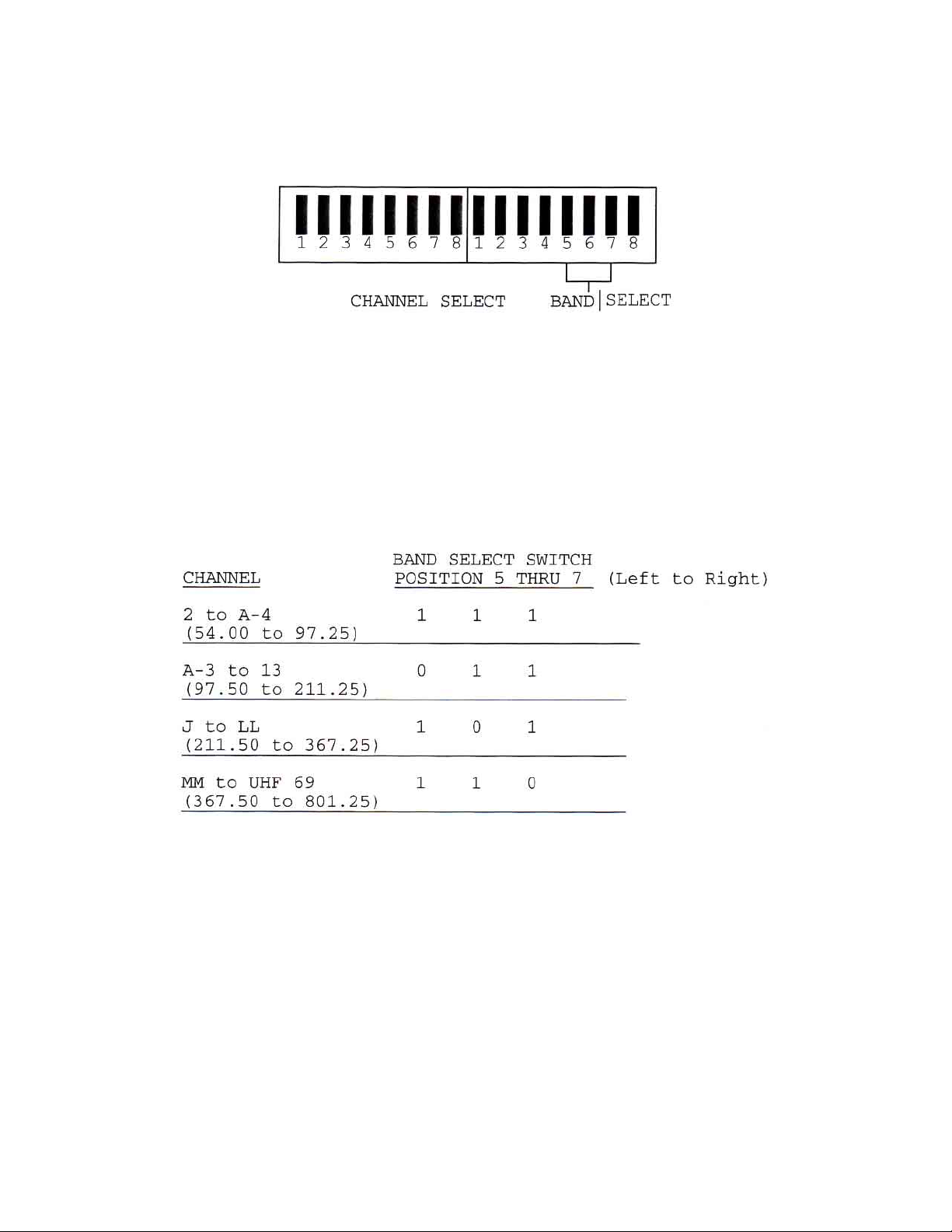
1) DEMODULA TOR OPERA TION
A) Input Channel selection - Remove the front panel plate on the “Input Channel Select” to expose the
channel select and band select DIP switches.
The channel select switch is the first 12 positions on the left side of the opening. The next 3 positions
are for band select and the last position is for AFC “On-Of f” selection. The channel select codes for
all standard input channels is attached to the DIP switch cover for operator’s convenience and also
appears on page 5 of this manual. To select an HRC input channel, utilize the HRC code page
attached to the manual. T o select a channel, follow the code sheet from left to right placing the DIP
switch in either the up or down position as indicated by the code sheet. (0 = DOWN, 1 = UP)
The band select switch for the channel selected is as follows:
B) AFC selection - Most off air TV stations are usually very close to the specified carrier frequency
C) Off cable processing should not require AFC but make sure the proper code sheet (standard
025-000053 REV G
This information is also included on the code cards attached to the cover plate.
such that the AFC function need not be used. However , some UHF stations have a tendency to
drift so it is best to utilize the AFC function. Simply put the AFC switch (last switch on the right) in
the down position for automatic frequency control.
channel or HRC) is utilized.
Page 4
Page 5

D) After an input channel has been selected, connect an antenna or cable source to the “VHF/UHF”
terminal. For optimum video quality , the input signal level should be -10dBmV to +25dBmV for offair and -10dBmV to +10dBmV for of f-cable signals. Although the unit will function with input signals
as low as -20dBmV, levels below -20dBmV will be squelched in the output video amplifier by the
internal squelch circuit. T wo baseband video output ports are provided - one of which can be utilized
for on-line application where a monitor feature is required. Baseband video will include composite
audio subcarrier
if the “composite switch” on the rear panel is in the ON position. Baseband audio will
appear at the audio output screw terminals. A multiplex (MPX) output terminal is provided for broadcast stereo applications along with an i.f. (45.75) output port which allows the unit to be used as a
frequency agile input tuner for processor application. The OTD-3000 also provides a 4.5MHz audio
output port which can be utilized when using a modulator with 4.5MHz audio carrier input capabilities,
such as the Olson Model OTM-3000-CV.
E) The baseband video output is internally set for lV p-p video output (±10%) with a 75 ohm termination.
The baseband audio output is internally set for 500mV p-p at standard broadcast deviation. The
Audio Output termination can be as low as 600 ohms.
The MPX Output is 75 ohms and need not be terminated.
F) The Demodulator Delayed AGC Adjustment is factory set and provides the best signal-to-noise
ratio for low-level off-air signals and for adjacent channel rejection with cable operation.
025-000053 REV G
Page 5
Page 6
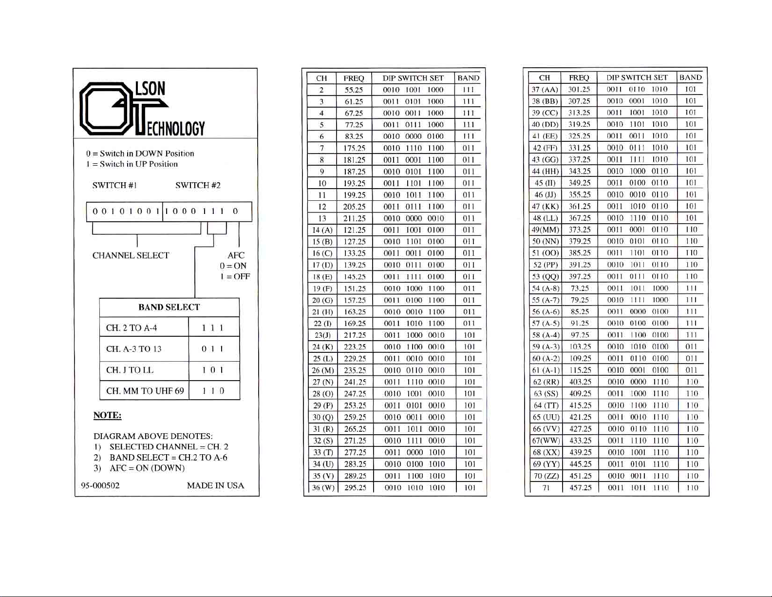
ST ANDARD CHANNEL CODES FOR OTD-3000
025-000053 REV G
Page 6
Page 7
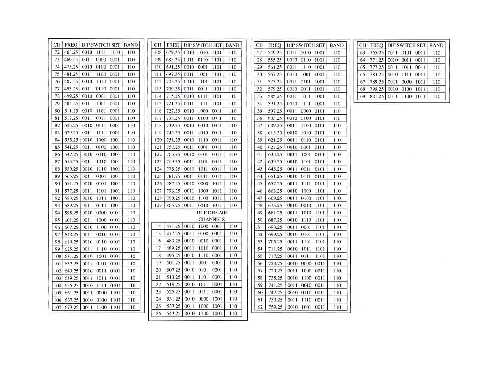
ST ANDARD CHANNEL CODES FOR OTD-3000 (continued)
025-000053 REV G
Page 7
Page 8
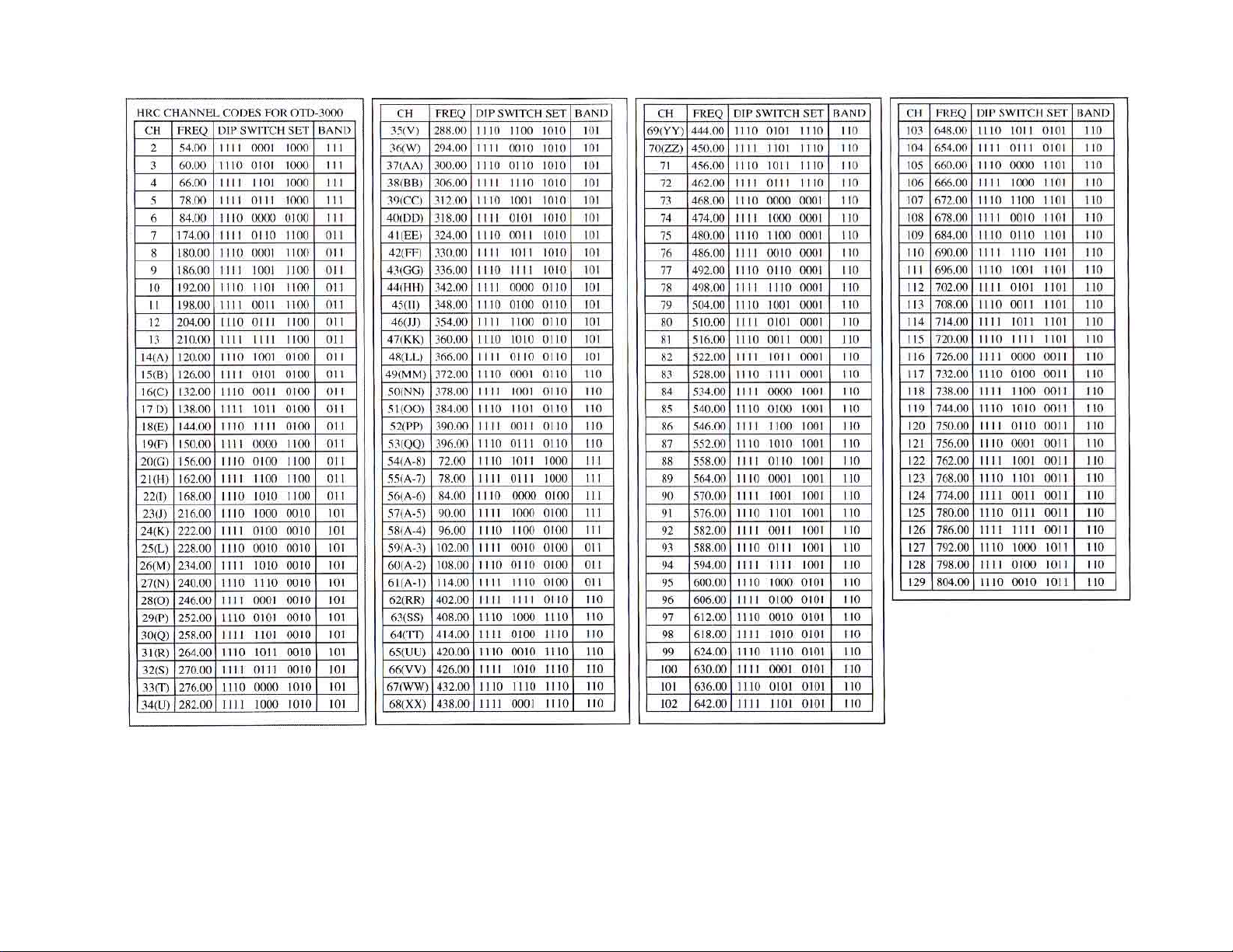
H R C CODES FOR OTD-3000 DEMODULA TOR
025-000053 REV G
Page 8
Page 9
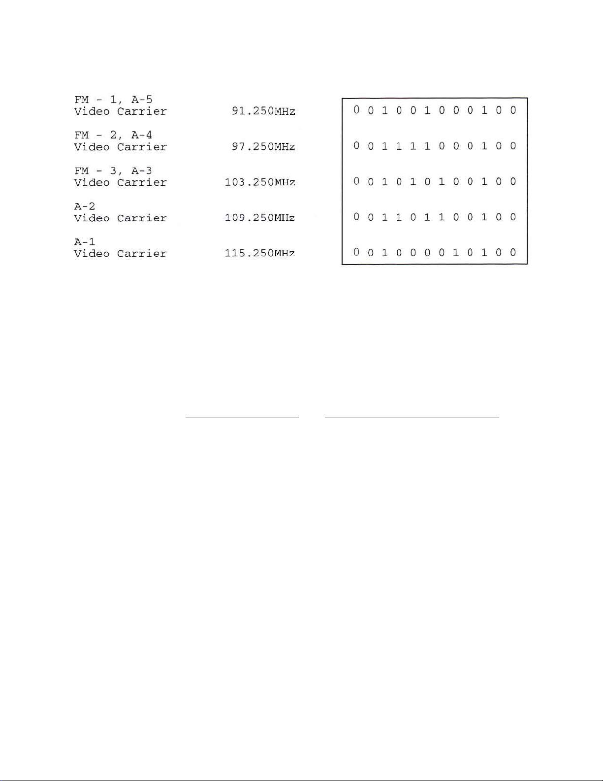
OTD-3000 DEMODULA TOR CODES
FOR
NON-ST ANDARD CHANNELS
COMPUTING SWITCH SETTINGS FOR NON-ST ANDARD FREQUENCIES
The OTD-3000 can be set for any frequency between 54.00 and 801.25MHz in .25MHz steps.
Positions 1 through 8 of the left switch and positions 1 through 4 of the right switch each have
decimal values as shown in figure 2 below .
LEFT SWITCH RIGHT SWITCH
Switch position 1 2 3 4 5 6 7 8 1 2 3 4 5 6 7 8
BAND
Decimal Number 1 2 4 8 16 32 64 128 256 512 1024 2048
SWITCH
Binary Number 1 1 1 1 1 1 1 0 0 1 0 0
The Binary number shown is for 114.00MHz.
FIGURE 2 - DIP SWITCH V ALUES
A) Decide on the desired frequency yyy .xx.
B) Compute the L.O. frequency required by adding 45.75 to the desired frequency.
C) Divide the L.O. frequency by the step size, .25 to obtain “divide by N”.
AFC
D) Convert “N” to reversed binary (least significant bit on the left) using chart.
E ) Select the proper input tuner band and set the switches 5, 6 and 7 of the right side switch per chart
025-000053 REV G
on page 4.
Page 9
Page 10

EXAMPLE:
A) Example frequency of 114.00MHz is desired.
B ) N = (1 14.00 + 45.75) / .25 = 639, the total switch value required.
C) Consult the chart above and locate the largest decimal number that is
less than or equal to 639.
This would be 512. Place a “1” below 512.
Subtract this number from 639 to obtain the remainder for the next step. The remaining number will
be 127. (639-512=127)
D) Consult the chart and locate the largest number that is
less than or equal to 127. This is 64. Place a “1”
below 64.
Subtract 64 from 127 to obtain the remainder (127-64=63)
E) Continue in this manner until the remainder is zero.
F) Place a “0” below all other decimal numbers that did not receive a “1”.
The resulting reversed binary number is:
1111 1110 0100
G) Consult the bandswitch chart on page 4 and 1 14.00MHz is between 97.50 and 211.25.Set the
bandswitch to: 011
025-000053 REV G
Page 10
Page 11

OTD-3000
TROUBLESHOOTING ADDENDUM
Troubleshooting:
1) This unit has a restricted AFC range. This is done to eliminate a problem inherent in many low cost modulators
incorporating AFC. That problem occurs when the desired off-air channel goes off the air and the AFC has a
wide enough range to pull in an adjacent channel. In most cases the AFC holds the undesired channel when the
desired channel returns to the air .
2) However, many independent UHF broadcast stations and translators operate out of specification with regard
to F .C.C. rules. W e have found some in excess of 1MHz from their specified channel allocations. Fortunately
your demodulator is capable of selecting the L.O. frequency in 0.25MHz increments. This will allow you to
select an L.O. frequency to compensate for your UHF station error.
3) Make sure that the DIP switches for Channel Select are in the correct position according to the channel select
chart. Ensure that the Band Select Switches are in the proper position. Put the AFC switch in the “Of f” or up
position.
If you hear audio but no video is present, your input level to the UHF input is either too low (-20dBmV or
below) which triggers an internal squelch circuit or the UHF transmitter may be off frequency . An of f frequency
input will cause the unit to act like a low level input signal because it will run the video carrier down the rejection
slope of the IF SA W filter .
If a field strength meter is available, measure the UHF input level for the channel of interest. If it is below
-10dBmV , a preamplifier is recommended. If possible, view the UHF signal on a TV set and ensure that you
have an adequate picture. If properly set-up, the OTD-3000 should produce a picture of comparable video
quality .
View the video output on a suitable composite video monitor . If it is of comparable quality to the off-air
signal, the unit and the TV station are both operating properly .
If the picture is of inferior quality or there is no picture, begin changing the L.O. frequency by the following
procedure:
1) The first two DIP switches as viewed from left to right are always in the down position and the third
switch is always in the up position for standard frequency allocations.
2) Moving the first switch to the UP position will increase the L.O. by 0.25MHz. If the picture improves
significantly , move the 2nd DIP switch to the UP position, and the first switch back to the DOWN position.
This increases the L.O. by 0.50MHz. If the picture quality is not as good as with 0.25MHz offset, return to
the 0.25 offset position (lst switch UP) and activate the AFC switch (DOWN position).
025-000053 REV G
Page 11
Page 12

3) If the picture quality gets worse in step (2) above by increasing the L.O., the following procedure should be
implemented.
Move the lst and 2nd DIP switch to the UP position and the 3rd DIP switch to the DOWN position. This
moves the L.O. down by 0.25MHz. If the picture quality improves, try putting the lst position in the DOWN
position, leaving the 2nd switch in the UP position and the 3rd switch in the DOWN position. Determine which
position gives better quality and activate the AFC switch.
EXAMPLES: Channel 14 (UHF)
No offset 0 0 1 0 1 0 0 0 0 0 0 1
(From std. chart)
--------------------------------------------------------
+0.25mHz offset 1 0 1 0 1 0 0 0 0 0 0 1
--------------------------------------------------------
+0.50mHz offset 0 1 1 0 1 0 0 0 0 0 0 1
--------------------------------------------------------
-0.25mHz offset 1 1 0 0 1 0 0 0 0 0 0 1
--------------------------------------------------------
-0.50mHz offset 0 1 0 0 1 0 0 0 0 0 0 1
If this procedure does not yield any improvement, please consult the factory .
025-000053 REV G
Page 12
 Loading...