

Page 1

NTM-324x SERIES RETURN TRANSMITTER
INSTRUCTION MANUAL
NTM-324x-xx/xxx
INSTRUCTION MANUAL
Phone:
E-Mail: [email protected]
025-370527 REV X1 3-31-06
(209) 586-1022
(800) 545-1022
Fax:
(209) 586-1026
www.olsontech.com
Page 2

TABLE OF CONTENTS
SAFETY WARNINGS Page 3
INTRODUCTION Page 4
INSTALLATION Page 4
Installation/Environmental Considerations Page 4
Optical Connectors and Cleaning Page 4
External Test Points Page 4
Alignment Procedure Page 5
025-370527 REV X1
Page 2
Page 3

SAFETY WARNINGS
LASER RADIATION
The NTM-324x laser transmitter emits invisible laser radiation that can cause
permanent eye damage. AVOID DIRECT EXPOSURE TO BEAM.
Operate the transmitter only with the proper optical fiber installed in the
transmitter optical connector. The power to the NTM-324x should be turned off whenever the optical connector is
opened or exposed (as when the fiber connection is being installed or removed from the transmitter connector).
NEVER USE ANY OPTICAL INSTRUMENT TO VIEW THE OUTPUT OF THE LASER
TRANSMITTER. “OPTICAL INSTRUMENT” INCLUDES MAGNIFYING GLASSES, ETC.
NEVER LOOK INTO THE OUTPUT OF THE LASER TRANSMITTER
NEVER LOOK INTO THE OUTPUT OF A FIBER CONNECTED TO A LASER
TRANSMITTER.
NEVER LOOK INTO OR USE ANY OPTICAL INSTRUMENT TO VIEW THE DISTANT
END OF A FIBER THAT MAY BE CONNECTED DIRECTLY OR VIA AN OPTICAL SPLIT,
TO A TRANSMITTER THAT MAY BE OPERATING. THIS SPECIFICALLY APPLIES TO
FIBERS THAT ARE TO BE CONNECTED TO RECEIVERS OR
OTHER DEVICES AT ANY DISTANCE FROM THE LASER TRANSMITTER.
SHOCK HAZARD
Care should be used when installing the NTM-324x to prevent shock and
injury as there are voltages within the Node which exceed 48 VAC.
025-370527 REV X1
Page 3
Page 4

INTRODUCTION
The Olson Technology Inc. NTM-324x is a high quality, cost effective, Return Transmitter module designed around the latest
optical transmitter technology. It is designed to operate and meet full specifications with an optical output level of 1 to 3 mW. The
transmitter RF path includes a plug-in OMI pad which is preset at the factory for +3 dBmV per carrier with 6 channel loading.
The NTM-324x receives preconditioned +12 VDC from the Node and plugs directly into the preexisting locations within the Node.
The primary RF connection is made through the built in SMB connector on the bottom of the transmitter. The 5-42Mhz
connection is made through the 12 pin connector on the bottom of the module for use with the status monitoring unit. The
transmitter can be ordered with an optical connection that will match the factory setup. Heat transfer for the NTM-324x is
provided via the bottom surface of the module to the Node housing for full outdoor temperature operation.
INSTALLATION / ENVIRONMENTAL CONSIDERATIONS
The NTM-324x operates with an exterior temperature on the Node of -40 to + 60°C. However, like any other electronic device, it
will probably have a longer life span if it is not operated at the upper limit of it's temperature range continuously. Installation of
the NTM-324x should be done such that water, dirt and other contaminates do not enter either the Node or the module. Do not
install equipment in locations that are accessible by either children or other unqualified personnel. This unit is meant to be fieldinstalled into the HLN-3844 Optical Node by qualified field service technicians.
To install the NTM-324x, loosen the 6 closure bolts on the HLN-3844 Node casting enough free them from the other half of the
housing. Open the housing and locate the plug in module section of the Node. Place the NTM-324x module into position two for
a 4 to 1 configuration, making sure to orient the SMB and the 12 pin connector on the bottom of themodule in line with the mating
connector in the Node. For other configurations, refer to the HLN-3844 Node manual.
Push the NTM-324x into position firmly, seating the connectors. Tighten the three captive screws firmly. Connect the incoming
fiber to the transmitter, then dress the fiber as to keep it clear of anything that may pinch or damage it.
NOTE: Be sure the fiber termination of the incoming fiber matches that of the transmitter, an easy way to tell is by the color of the
termination. The transmitter will have either a green SA/APC, or a blue SC/UPC connector. The incoming fiber connector MUST
match this color. If the connector is green, but the fiber termination is blue (or vice versa), then the signal passing through the
fiber will be degraded and in many cases unusable.
OPTICAL CONNECTORS AND CLEANING
The standard optical connector provided with the NTM-324x is an SC/APC with an 8° angle. No tools are required for connection
to/from this type of optical connector.
The fiber ends can be damaged by the insertion of contaminated connectors into a bulkhead or receptacle, or by the insertion of a
clean connector into a dirty bulkhead. Fiber connectors should never be left uncovered. Optical connectors should be cleaned
before usage. Prepackaged alcohol wipes are the most convenient way to insure clean optical connectors. Fresh, clean alcohol
and lint free wipes or swabs may also be used.
EXTERNAL TEST POINTS
The NTM-324x has two external test points. One for optical power output calibrated at 1V/mW. It should be monitored with a high
impedance voltmeter. This test point is for long term monitoring purposes. The optical output power should be measured using
an optical power meter at the time of installation. The second is a -10dBmV for monitoring the RF input level to the transmitter.
025-370527 REV X1
Page 4
Page 5
ALIGNMENT PROCEDURE
The NTM-324x optical transmitter’s OMI has been optimized with an RF input level of +3.0dBmV per carrier (Six analog carriers)
maximum loading at the transmitters input. Do to the number of different configurations offered for the HLN-384x node, the
amount of loss through the node can vary by a substantial amount. Therefore transmitter drive levels should be set via the -10dB
test point.
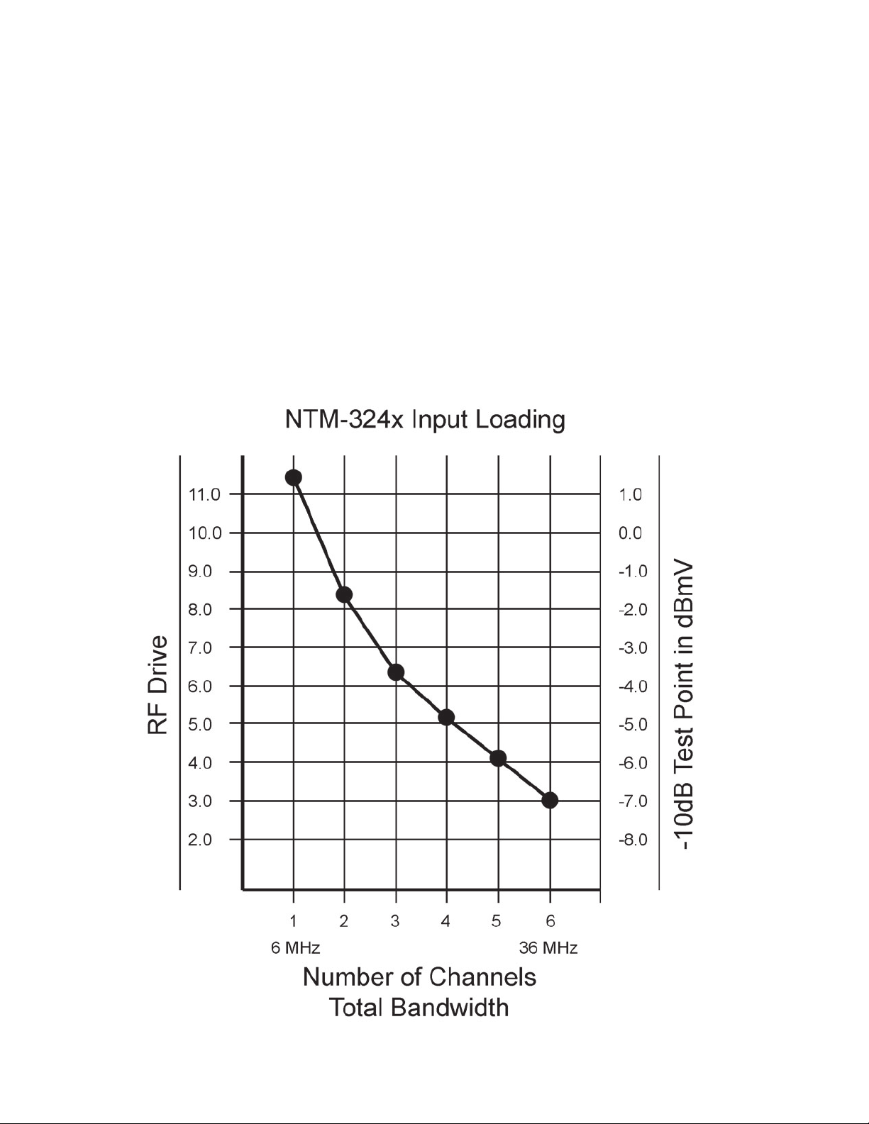
The chart below shows what drive levels are required for a given number of channels or QAM/QPSK loading. The units are setup
at the factory for an input level of +3dBmV per carrier with six carrier loading at the transmitter input. The level going into the
node will vary depending on the nodes configuration.
For Example, if the transmitter is going to be loaded with three video channels, than the test point needs to be approximately
-3.75dBmV per carrier. This level can be attained by changing the RF input PAD on the transmitter module. Increasing the PAD
value will lower the RF input level, while decreasing it will raise the RF input level.
If QAM, QPSK, or similar digital loading is being used, than the loading is calculated by total bandwidth rather than the number
of channels. If loading from 5 to 25MHz, than the input level will be set for 20MHz of total bandwidth. The chart below shows us
that 20MHz of bandwidth is equivalent to approximately 3.5 video channels, or an RF test point level of -4.25dBmV per channel.
025-370527 REV X1
Page 5
 Loading...