

Page 1

LCM-550x12
SERIES
Phone:
E-Mail: [email protected]
(209) 586-1022
(800) 545-1022
Fax:
(209) 586-1026
www.olsontech.com
6/1/01
Page 2

Section I: Modulators
1. LCM-550x1
2. LCM-550x1 PAL I
3. LCM-550x1 P AL BG
Section II: Demodulators
1. LCD-550x1
4. LCD-550x1 P AL D/K
Section III: Amplifiers
1. LCX12-AMP
Section IV : Combiners
LCM-550x12 Series
1. LCM-550-FAC
Phone:
E-Mail: [email protected]
(209) 586-1022
(800) 545-1022
Fax:
(209) 586-1026
www.olsontech.com
6/1/01
Page 3

LCM-550x12
12 CHANNEL TELEVISION MODULATOR SYSTEM
INSTRUCTION MANUAL
Phone:
E-Mail: [email protected]
025-000329 REV C 6/1/01
(209) 586-1022
(800) 545-1022
Fax:
(209) 586-1026
www.olsontech.com
Page 4

LCM-550x12
Frequency Agile Modulator System
Specifications
Output Frequency Range: 55.25 to 547.25MHz in 2MHz increments, selected by front panel
DIP switch. 250KHz increments internally selectable for HRC
frequencies.
Output Power: +40dBmV minimum, +45dBmV typical per channel. Downward
adjustable by 10dB minimum.
Spurious Outputs: >60dB below output video carrier out of band.
Out-of-Band C/N: >80dB below output video carrier (4MHz bandwidth) - per channel.
In-Band C/N: >57dB
Frequency Stability/Accuracy: Designed to meet F.C.C. title 47 part 76 (+10 Celsius to + 40 Cel-
sius). Offset adjustable by front panel potentiometer .
Audio/Video Ratio Adjust: From 13dB to 20dB below video carrier. Adjustable by front panel
potentiometer.
Audio Intercarrier Accuracy: 4.5MHz +/- 1KHz
Video Input: 1V P-P nominal for 85% modulation. Front panel adjustable, from as
low as 0.5V P-P input. 75 Ohm input Z utilizing an RCA connector.
Audio Input: 500mV P-P for 25KHz deviation. Adjustable by front panel potenti-
ometer. 10K input Z utilizing an RCA connector.
Power Requirements: 85 - 264VAC, 47 - 63Hz, 60 Watts maximum.
Size: 3.5”H x 19”W x 11”D (Rack Mount Chassis)
Weight: 10 LBS.
025-000329 REV C
Page 2
Page 5

12 CHANNEL, FREQUENCY AGILE - F.C.C. COMPATIBLE
1.) INTRODUCTION
The Olson T echnology LCM-550X12 can consist of twelve frequency agile F .C.C. compatible television
modulators in a single 3 ½” rack – mount chassis. The LCM-550X12 has a separate RF output for
each channel, and each channel may be operated at +45dBmV typical, +40dBmV guaranteed minimum. The LCM-550X12 modulator is compatible with baseband scrambling techniques. No I.F .
loops are provided on these modulators.
Each of the twelve modulators will operate on any standard or cable channel from 55.25MHz to
547.25MHz (VHF channels 2 through 13 and cable channels 14 through 78). All channels are selectable by front panel DIP switches and a front panel adjustment allows setting to F .C.C. of fset
frequencies. HRC frequencies are available.
LCM-550x12
TELEVISION MODULA TOR SYSTEM
Each of the modulators in the LCM-550X12 offers the unique Olson Technology feature of >80dB
out-of-band carrier to noise ratio. These units use SAW filtering for adjacent channel operation, and
provide 60dB of spurious free dynamic range. These features allow virtually unlimited numbers of
LCM-550X12’s to be combined without the need for external bandpass filters.
The LCM-550X12 has low power consumption (approximately 5 watts per channel @ 115 VAC) for
economical and reliable long term operation.
025-000329 REV C
Page 3
Page 6
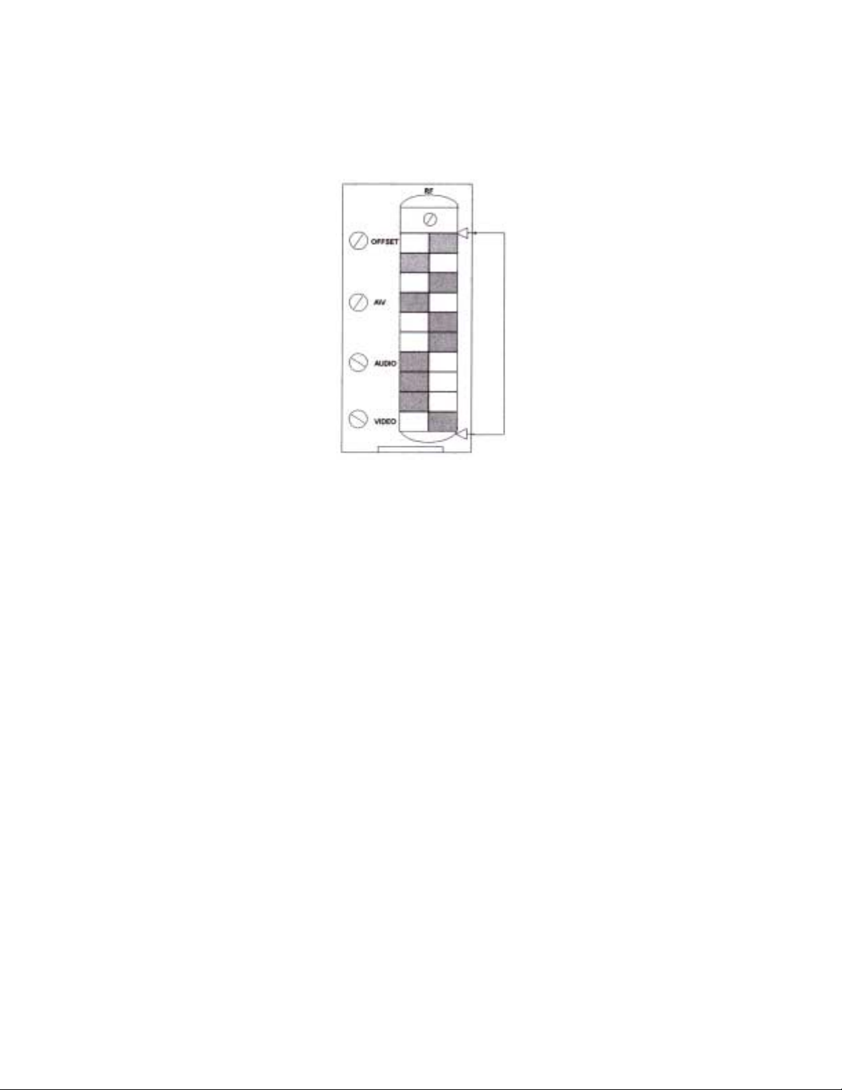
2.) CHANNEL SELECTION
Channel frequencies are selected by setting the 10-position DIP switch (visible through the vertical
slot in the front panel). The front panel is illustrated in figure 1.
Channel Select
Figure 1 – LCM-550 Front Panel
Switch-setting codes for standard channels are shown in Figure 2 and on the code card provided with the
system. Switch-setting codes for HRC channel frequencies can be found in T able 2 and Figure 3 in this
manual. The front panel illustration in Figure 1 shows a switch properly set for standard channel 2.
3.) F.C.C. OFFSET ADJUSTMENT
F.C.C. Offset frequencies are shown in Table 1 and summarized on the code card provided with the
system. To adjust the frequency of a selected channel to provide the correct F.C.C. offset, look up its
offset frequency in Table 1 (or use the summary on the code card). Remove the video input and
connect a counter to the RF output of the LCM-550. Use the front panel offset adjust control to set
the output frequency to the correct value.
025-000329 REV C
Page 4
Page 7
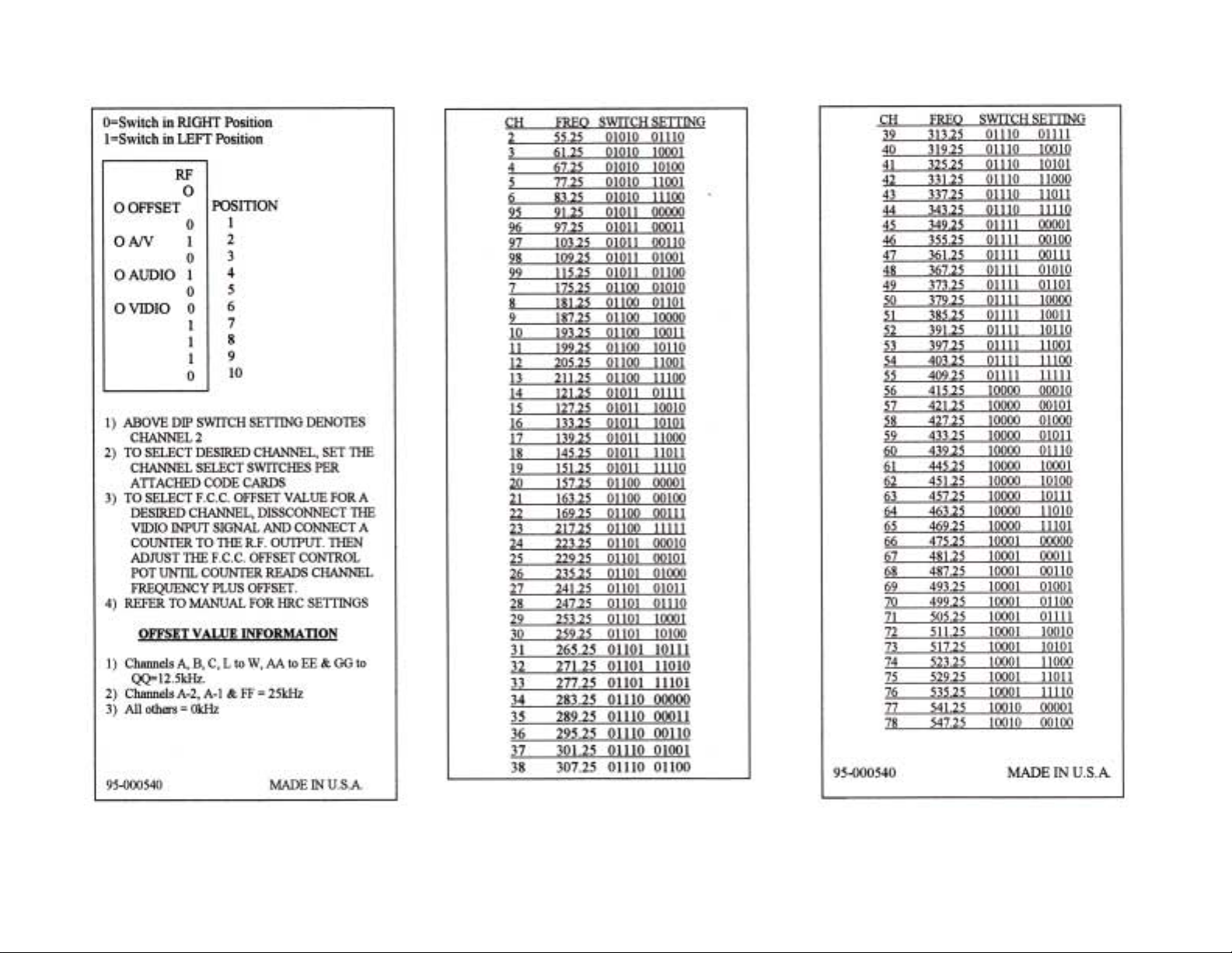
Figure 2 - CHANNEL SWITCH SETTING CODES
025-000329 REV C Page 5
Page 8
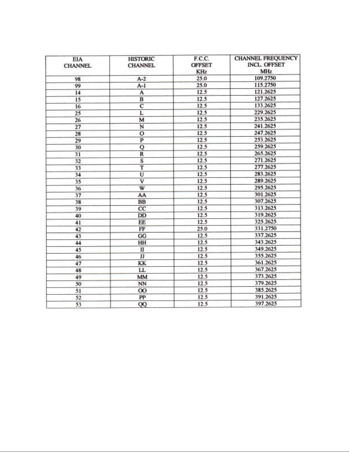
TABLE 1 F.C.C. OFFSET FREQUENCIES
025-000329 REV C
Page 6
Page 9
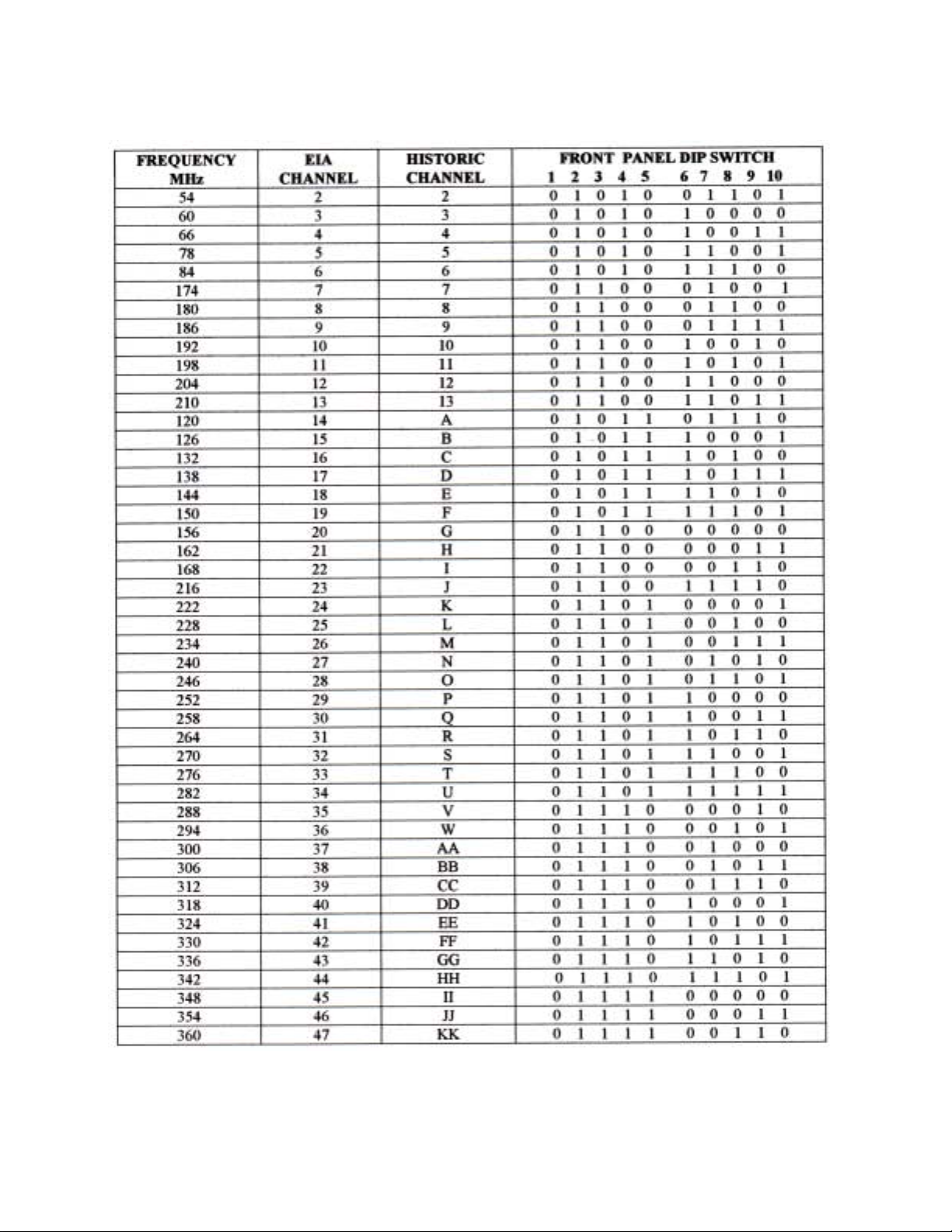
TABLE 2 HRC CHANNEL CODES
025-000329 REV C
Page 7
Page 10
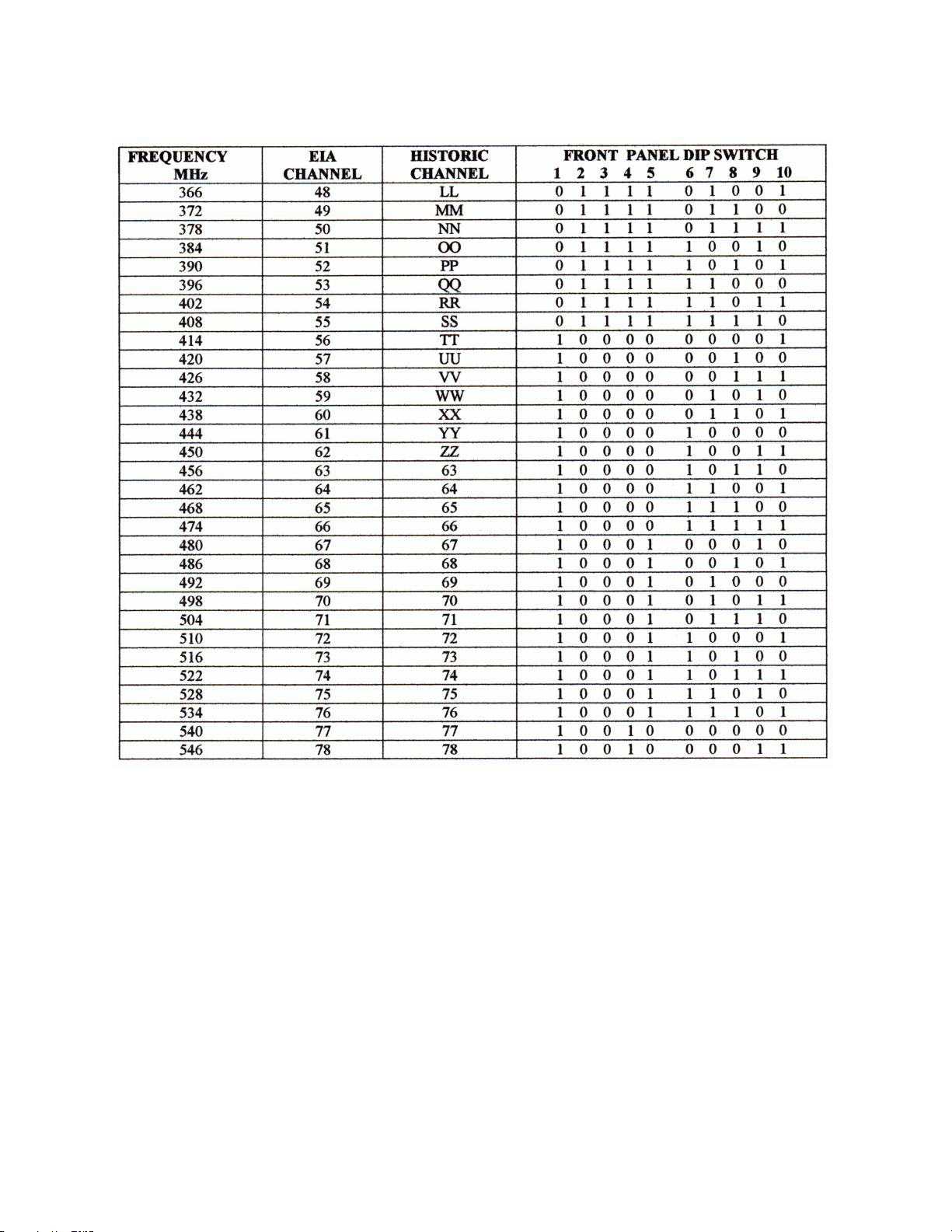
TABLE 2 CONTINUED. HRC CHANNEL CODES
025-000329 REV C
Page 10
Page 11
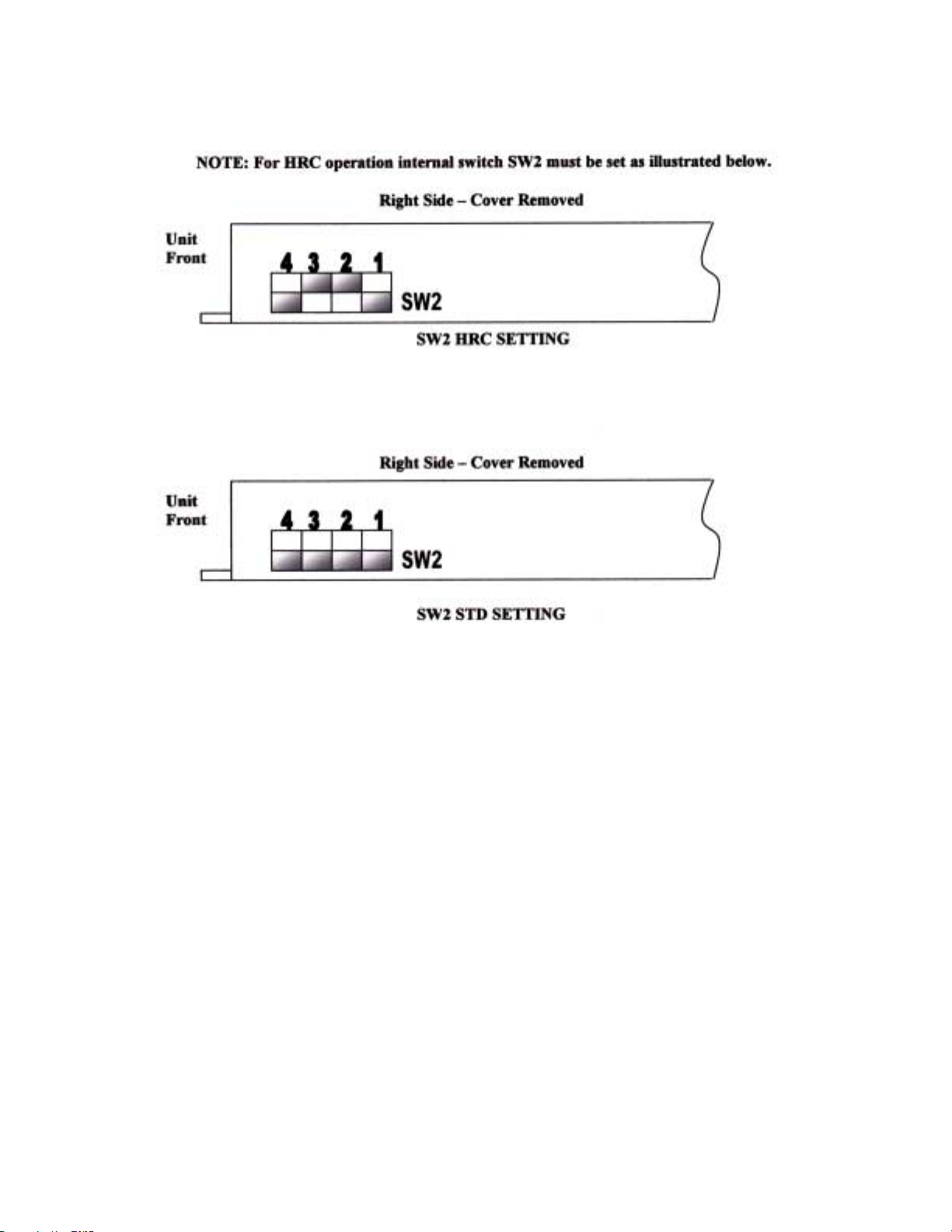
Figure - 3 INTERNAL SW2 SETTINGS FOR HRC / STD
025-000329 REV C
Page 9
Page 12

4.) REAR PANEL
The rear panel of each module has its audio and video inputs and its RF output. The audio and video inputs are RCA
type phono jacks and the RF output is a type “F”.
5.) VIDEO MODULATION ADJUSTMENT (Each modulator).
LCM-550X12 modulator modules are preset at the factory for 85% depth of modulation with a 1V P-P pulse and bar
test signal. If the video modulation needs to be adjusted, follow the procedure below.
Connect the video source (to be used at approximately 1V P-P) to the video input phono jack. The video should be of a
reasonably bright scene (commercials are usually excellent).
Adjust the video modulation control on the front panel to obtain approximately 85% depth-of modulation as measured
on a spectrum analyzer or other test equipment capable of this measurement.
If the video modulation control needs to be set and there is no test equipment available, it can be set fairly close by
comparison. View a video signal on a properly adjusted television receiver or receiver/monitor. Apply the same signal
if possible, or one of equivalent brightness and contrast to the modulator that needs to be set. View the output of this
modulator on the same receiver and adjust the video modulation control for brightness and contrast equivalent to the
directly viewed picture. Use caution and do not set this control too high.
6.) AUDIO MODULATION ADJUSTMENT (Each modulator).
Connect the audio source (to be used at approximately 500mV P-P) to the audio input phono jack.
Monitor the audio on a television receiver and adjust the audio modulation control for proper loudness as compared
with some channel known to be modulating at the correct level (such as a broadcast station).
The two sources of audio should be very similar in their content and should be near maximum loudness as compared to
the average level of their program. In other words, compare a loud passage with a loud passage and set the audio
modulation control with this program material. Use caution and do not set this control too high.
7.) OPERATION WITH COMPOSITE BASEBAND BTSC AUDIO INPUT (Each modulator).
The LCM-550X12 modulators are compatible with a composite baseband BTSC audio input. An internal jumper must
be changed to remove audio pre-emphasis as required for this application.
To remove audio pre-emphasis, disconnect and remove the LCM-550 module from the main shelf and remove its left
side cover. Cut board where indicated.
Replace the module cover, replace the module in the main shelf, and set-up the audio deviation per the instructions for
the BTSC generator being used.
8.) RF OUTPUT AND AURAL CARRIER LEVEL ADJUSTMENT (Each modulator).
A) Using a field strength meter or spectrum analyzer, set the video carrier to the desired level with the output level
(RF) control (typically +40 to +45dBmV).
B) Tune the field strength meter to the aural carrier, which is located 4.5 MHz above the video carrier.
C) Adjust the aural carrier level control (A\V) to the desired level, typically 15dB below the video carrier.
CAUTION: Reducing the aural \ visual carrier ratio to less than 15dB can result in high out-of-band spurious
signals on adjacent channels.
025-000329 REV C
Page 12
Page 13

9.) MISCELLANEOUS
A) The front panel adjustments (RF, OFFSET, etc.) are small, and somewhat delicate. Use CAUTION and an
adjustment tool that is a proper fit when adjusting these controls.
B) The LCM-550X12 is BTSC stereo compatible. Each modulator is shipped in the “mono” mode. To defeat the
pre-emphasis in order to use a composite baseband BTSC input signal, see section 7 of this manual.
C) The LCM-550X12 power supply is equipped with an internal 3Amp. 250V GMA fuse. For continued safety, and
to maintain proper performance of the unit, please replace only with an equivalent fuse.
025-000329 REV C
Page 13
Page 14

LCM-550X12
PAL I ADDENDUM
INSTRUCTION MANUAL
Phone:
E-Mail: [email protected]
025-370312 REV B 8/2/01
(209) 586-1022
(800) 545-1022
Fax:
(209) 586-1026
www.olsontech.com
Page 15

LCM-550X12
PAL I
Specifications
Output Frequency Range ........................... 48.25MHz to 551.25MHz. Selectable by front panel DIP switch in
2MHz increments (250KHz internal adjustment)
Frequency Offset ........................................ +12.5KHz tunable by front panel adjustment
Output Power Level ................................... +40dBmV minimum per channel, +45dBmV typical
Frequency Accuracy / Stability .................. <±5KHz of selected channel frequency (+10°C to +40°C)
Video Performance ..................................... 1V P-P input nominal for 80% modulation. Differential gain <5%
Differential Phase <5°
Spurious Outputs ........................................ >55dB below output visual carrier level, 60dB typical
Out-of-Band C/N ........................................ >76dB as measured in a 4.0MHz noise bandwidth
In-Band C/N ............................................... >60dB as measured in a 4.0MHz noise bandwidth
Audio / Video Ratio .................................... Adjustable from 13dB to20dB below video carrier
Audio Performance ..................................... 500mV P-P for 50KHz deviation, front panel adjustable.10K input Z
Audio Intercarrier Stability ........................ 6.0MHz within ±1KHz
Front Panel Controls .................................. RF output adjust
A/V ratio adjust
Video & Audio modulation
Frequency offset adjust
Channel select DIP switches
Power Requirements .................................. 85-264VAC, 47-63Hz, 72 watts
Chassis Size ............................................... 3.5”H x 19”W x 11”D (Rack mount chassis)
025-370312 REV B
Page 15
Page 16
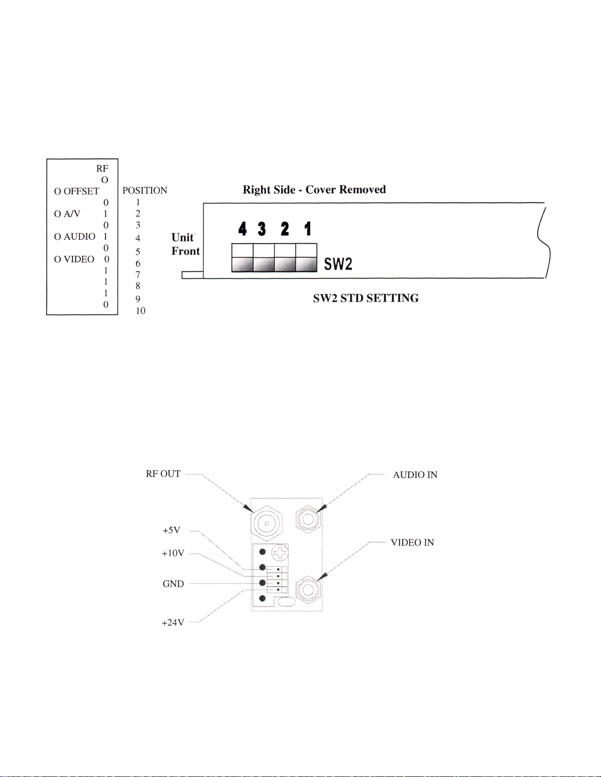
CHANNEL SELECTION
Channels are selected with 10 front panel DIP Switches and 3 internal DIP switches.
0=Switch in RIGHT Position
1=Switch in LEFT Position
Settings shown above are for channel 1, 55.25MHz.
REAR PANEL
The rear panel of each module has Audio and Video inputs, RF output and Power In. The Audio and Video
inputs are RCA type phono jacks and the RF output is type “F”.
025-370312 REV B
Page 16
Page 17
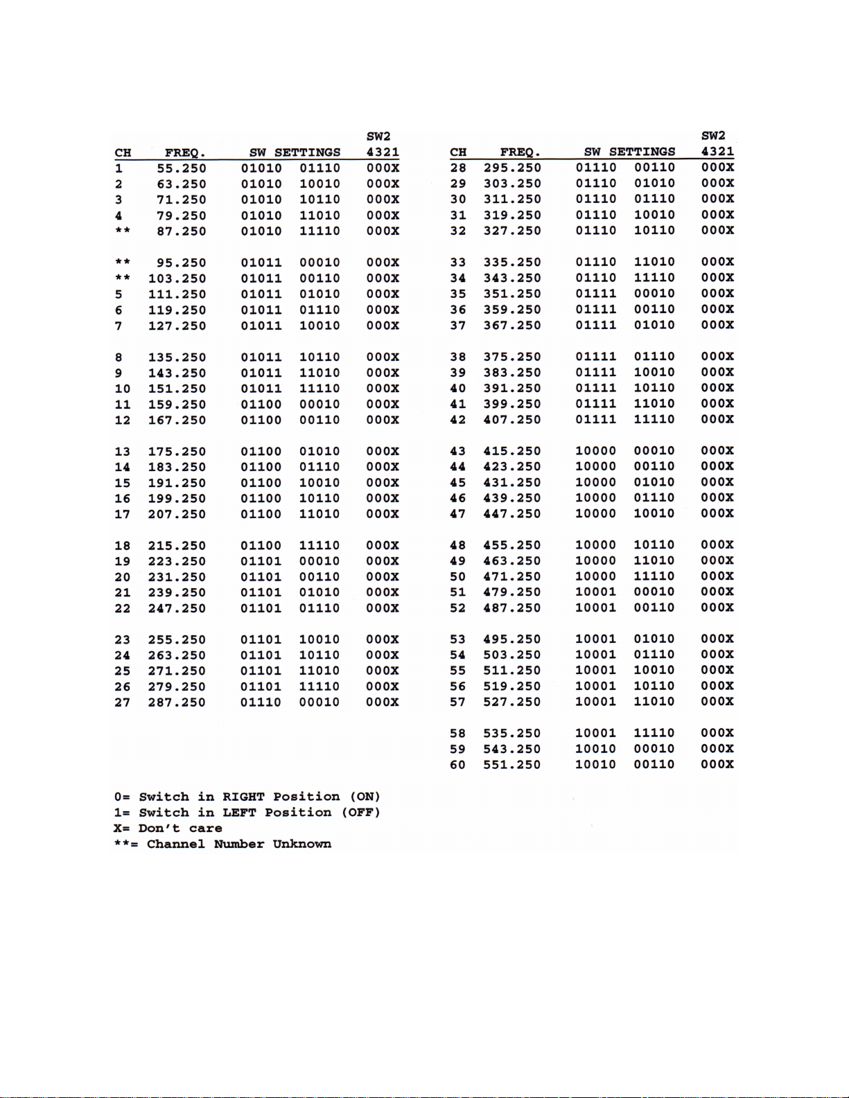
LCM-550-I Dip Switch Settings
025-370312 REV B
Page 17
Page 18

LCM-550X12
PAL B/G ADDENDUM
INSTRUCTION MANUAL
Phone:
E-Mail: [email protected]
025-370311 REV B 8/2/01
(209) 586-1022
(800) 545-1022
Fax:
(209) 586-1026
www.olsontech.com
Page 19

LCM-550X12
PAL B/G
SPECIFICAIONS
Output Frequency Range ........................... 48.25MHz to 551.25MHz. Selectable by front panel DIP switch in
2MHz increments (250KHz internal adjustment)
Frequency Offset ........................................ +12.5KHz tunable by front panel adjustment
Output Power Level ................................... +40dBmV minimum per channel, +45dBmV typical
Frequency Accuracy / Stability .................. <±5KHz of selected channel frequency (+10°C to +40°C)
Video Performance ..................................... 1V P-P input nominal for 80% modulation. Differential gain <5%
Differential Phase <5°
Spurious Outputs ........................................ >55dB below output visual carrier level, 60dB typical
Out-of-Band C/N ........................................ >76dB as measured in a 4.0MHz noise bandwidth
In-Band C/N ............................................... >60dB as measured in a 4.0MHz noise bandwidth
Audio / Video Ratio .................................... Adjustable from 13dB to20dB below video carrier
Audio Performance ..................................... 500mV P-P for 50KHz deviation, front panel adjustable.10K input Z
Audio Intercarrier Stability ........................ 5.5MHz within ±1KHz
Front Panel Controls .................................. RF output adjust
A/V ratio adjust
Video & Audio modulation
Frequency offset adjust
Channel select DIP switches
Power Requirements .................................. 85-264VAC, 47-63Hz, 72 watts
Chassis Size ................................................. 3.5”H x 19”W x 11”D (Rack mount chassis)
025-370311 REV B
Page 19
Page 20
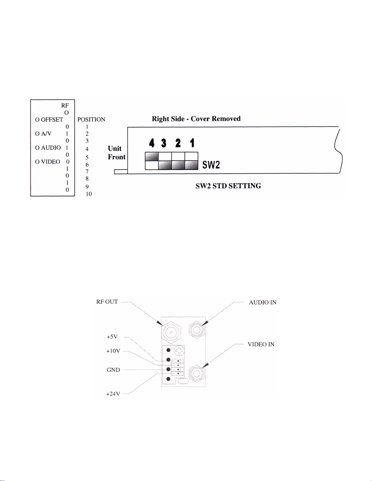
CHANNEL SELECTION
Channels are selected with 10 front panel DIP Switches and 3 internal DIP switches.
0=Switch in RIGHT Position
1=Switch in LEFT Position
Settings shown above are for channel 2, 48.25MHz.
REAR PANEL
The rear panel of each module has Audio and Video inputs, RF output and Power In. The Audio and Video
inputs are RCA type phono jacks and the RF output is type “F”.
025-370311 REV B
Page 3
Page 21
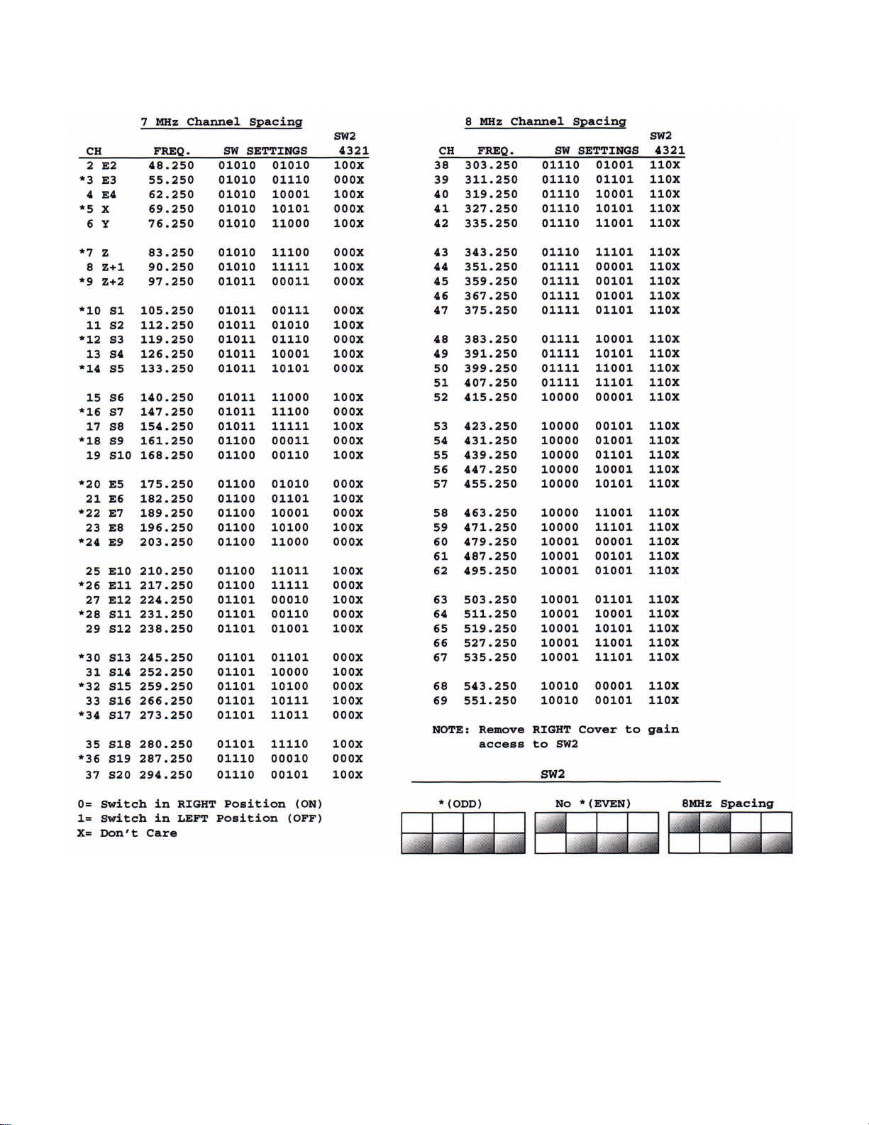
LCM-550 B/G Dip Switch Settings
025-370311 REV B
Page 4
Page 22

LCD-550
LOW COST AGILE
TELEVISION DEMODULATOR
INSTRUCTION MANUAL
Phone:
E-Mail: [email protected]
025-000345 REV B 8/21/01
(209) 586-1022
(800) 545-1022
Fax:
(209) 586-1026
www.olsontech.com
Page 23

CAUTION!
USE CARE WHEN CHANGING CHANNELS OR MAKING ADJUSTMENTS TO THE
LCD-550 MODULES
These units are very small and they use smaller (and more delicate) components than are normally found in larger
equipment.
The DIP switch levers can be damaged by excessive force. Use a small pointed object to gently move the switch
levers to the required positions.
The rotating controls can be pushed-in and broken if too much force is applied against them. When adjusting these
controls, use caution and an alignment tool in good condition that is a good fit to the control slot.
025-000345 REV B Page 2
Page 24
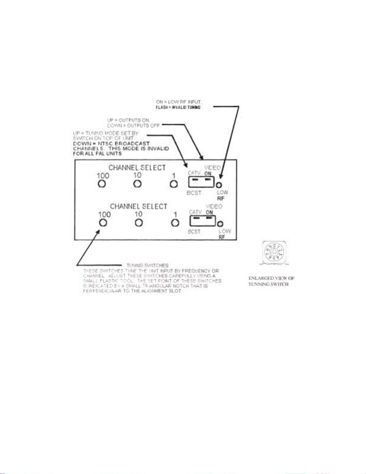
FRONT PANEL CONTROLS
Front panel controls should be adjusted only with plastic alignment tools. Damage may result if metal tools
are used. Refer to the following figure for the location of the front panel controls.
Figure 1
The LOW RF LED turns on with low or missing RF input. It also flashes on invalid tuning or mode settings. All outputs
are squelched with low RF or invalid tuning.
The VIDEO ON dipswitch turns all outputs on and off.
The CA TV-BCST dipswitch changes the tuning mode. In the CA TV position the tuning mode is set by the tuning mode
switch on the top of the demod. The BCST mode tunes NTSC broadcast VHF/UHF channels. This mode is invalid
for all P AL units.
The channel select switches tune the RF input frequency . The set point of these switches is indicated by a small
triangular notch that is perpendicular to the adjustment slot. When tuning by frequency , these switches are the
frequency in MHz, with the .25MHz steps set by the tuning mode switch.
025-000345 REV B
Page 4
Page 25
OPERATION
Most adjustments require removing the top cover. T o access the bottom unit in a dual version, remove the 2
screws holding the top demod to the front panel. T o access the internal adjustments, it is not necessary to remove the
demod from the front panel; just remove the top cover screws. Figure 2 shows the adjustment locations. When all
adjustments are complete, replace the top cover. For dual units, repeat this process for the top unit.
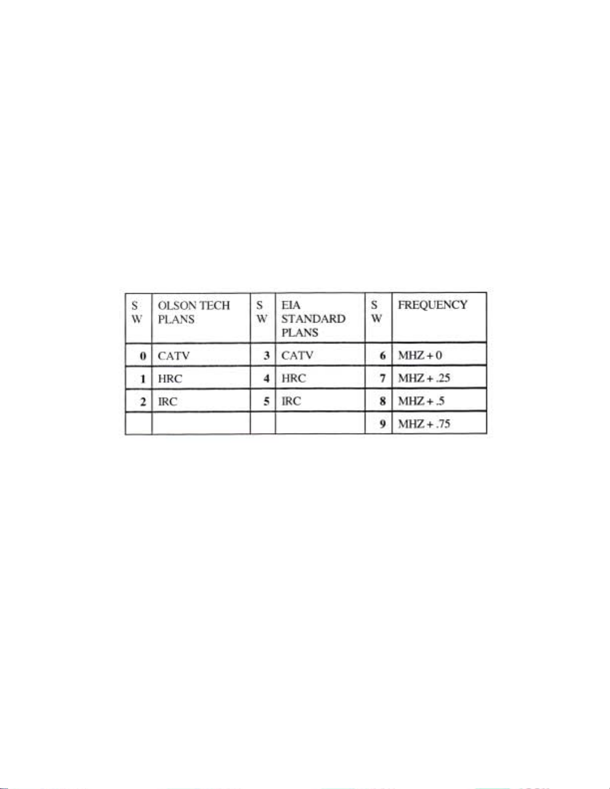
MODE SWITCH
This switch selects the CA TV tuning mode. It is accessed through a hole in the top cover . Note that P AL
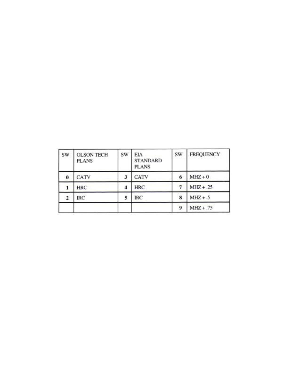
units tune by frequency only . Positions 0-2 select traditional channel plans. Positions 3-5 select EIA standard
channel plans. Positions 6-9 select direct frequency tuning.
025-000345 REV B
Page 5
Page 26

TROUBLESHOOTING
No output, low RF LED on:
RF input low or absent.
Incorrect tuning mode or channel.
Check the small triangular notch for switch settings.
No output, low RF LED flashes:
Invalid tuning. Check tuning and mode switches. P AL units tune by frequency only . Broadcast
channel mode is also invalid for P AL.
V ideo output very high contrast and distorted:
V ideo output is unterminated.
V ideo output washed out:
V ideo output is double terminated.
Audio problems:
V erify correct jumper settings. Pre-emphasis setting on modulator must
match that of demodulator .
025-000345 REV B
Page 7
Page 27

LCD-550-X1
SPECIFICATIONS
RF Input................................................
RF Input Level.......................................
V ideo Output.........................................
V ideo Performance.................................
Audio Output T ypes...............................
Audio Output.........................................
MPX Audio Output (NTSC)..................
Audio Subcarrier Output........................
NTSC 54 to 801.25MHz
Off-air -10dBmV to +25dBmV
CA TV -10dBmV to +10dBmV
1V p-p +/- 5 IRE into 75Ω
Diff. gain < 5%
Diff. phase < 3°
Normal Audio
Multiplex Audio
Subcarrier
(selected by internal jumpers)
500 mV p-p into 600Ω unbalanced
500 mV p-p into 600Ω unbalanced
> +40dBmV into 75Ω unbalanced
Front Panel Controls..............................
Front Panel Indicator..............................
Rear Panel Connectors...........................
Power Requirements..............................
Size.......................................................
Weight...................................................
Output on/off
CATV/Broadcast
Rotary tuning switches
Low RF
RF in, V ideo out...type “F”
Audio...RCA
< 2 watts from LCM-550 RKA chassis
(5V @ 165mA and 10V @ 30mA typical)
1.3x3x6
< 1 lb.
025-000345 REV B
Page 8
Page 28
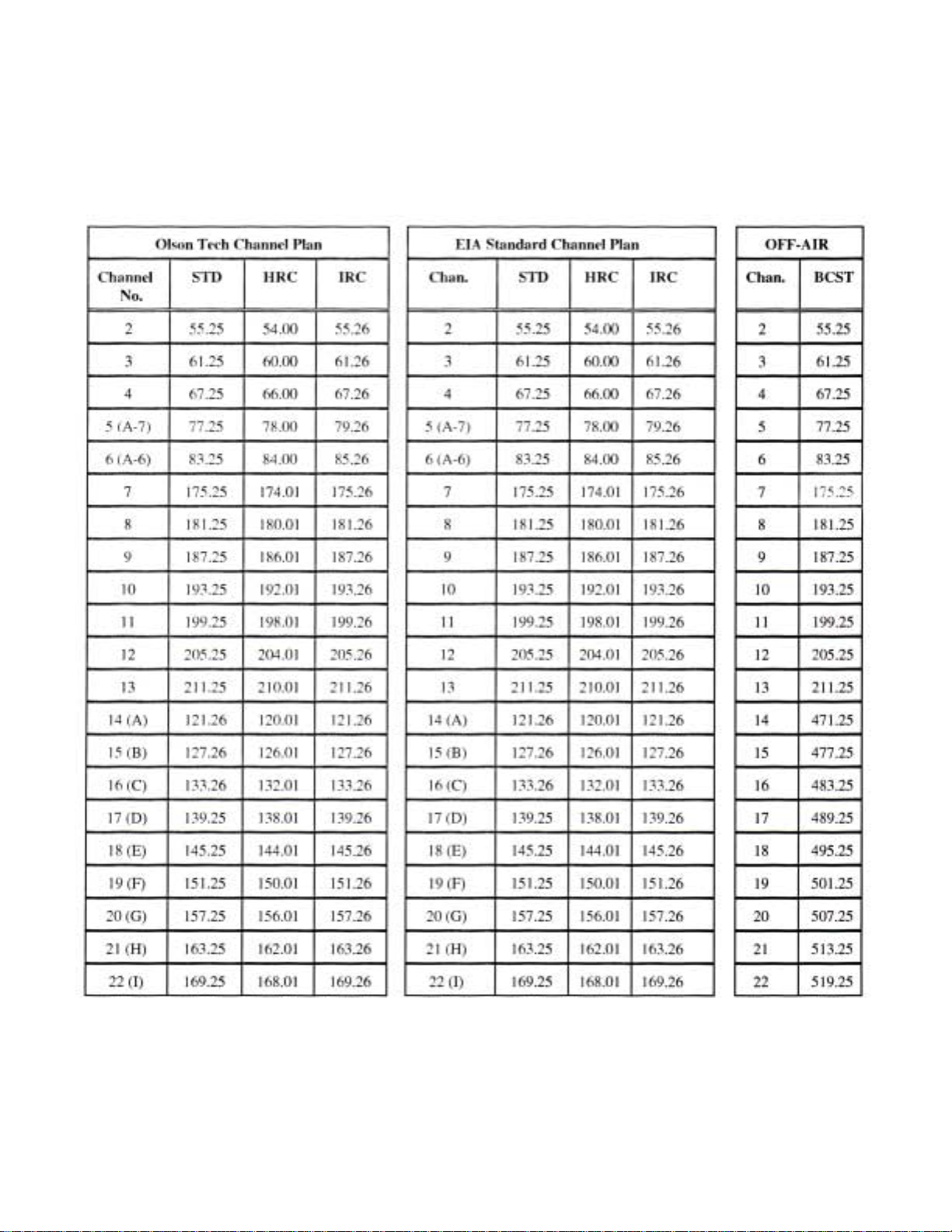
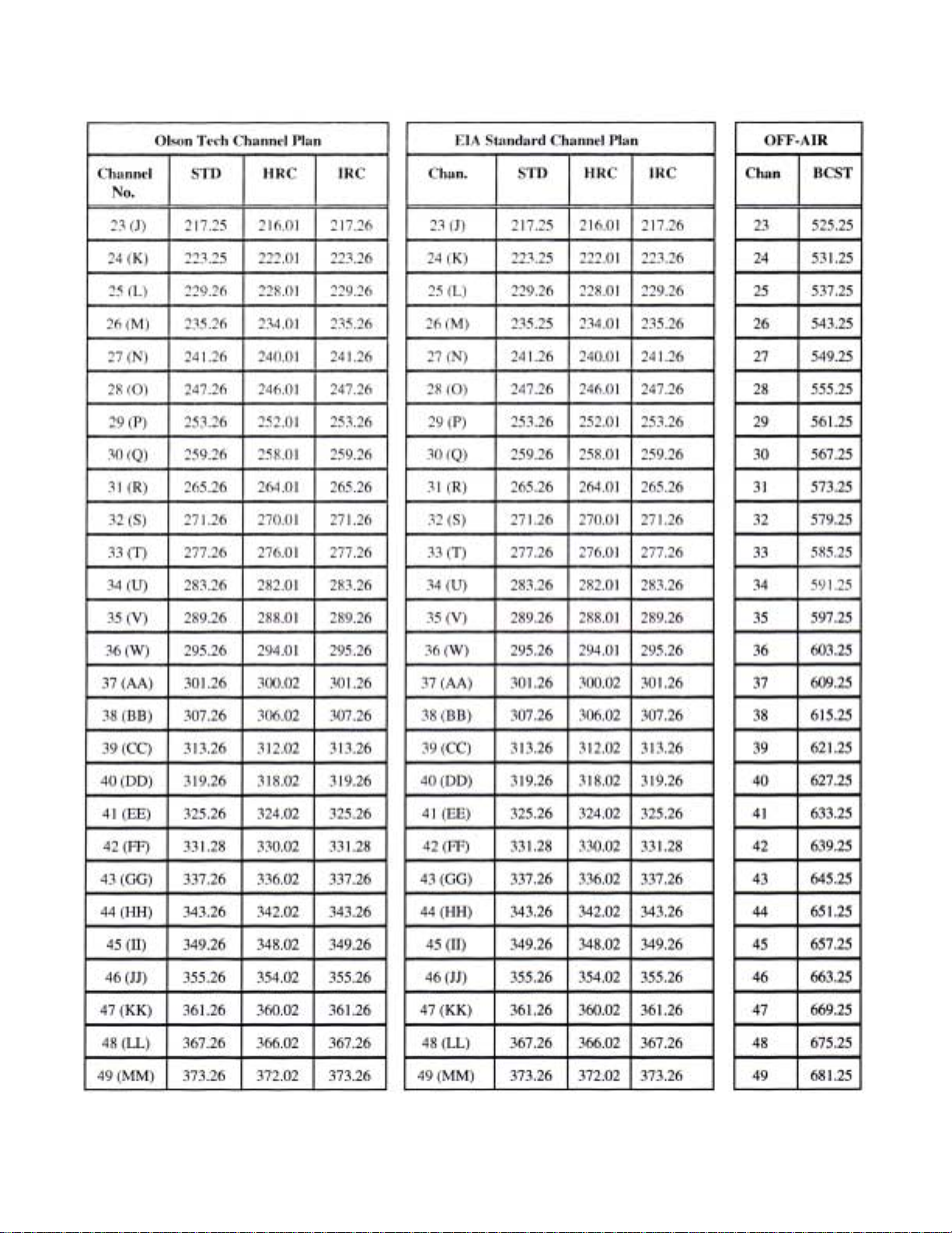
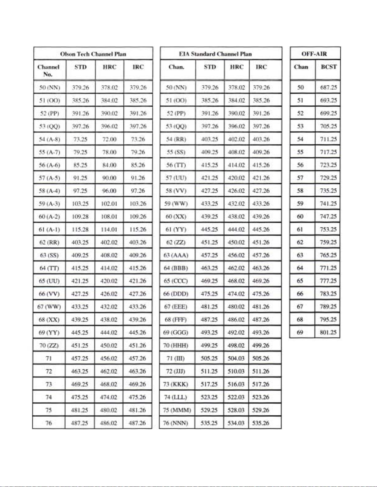
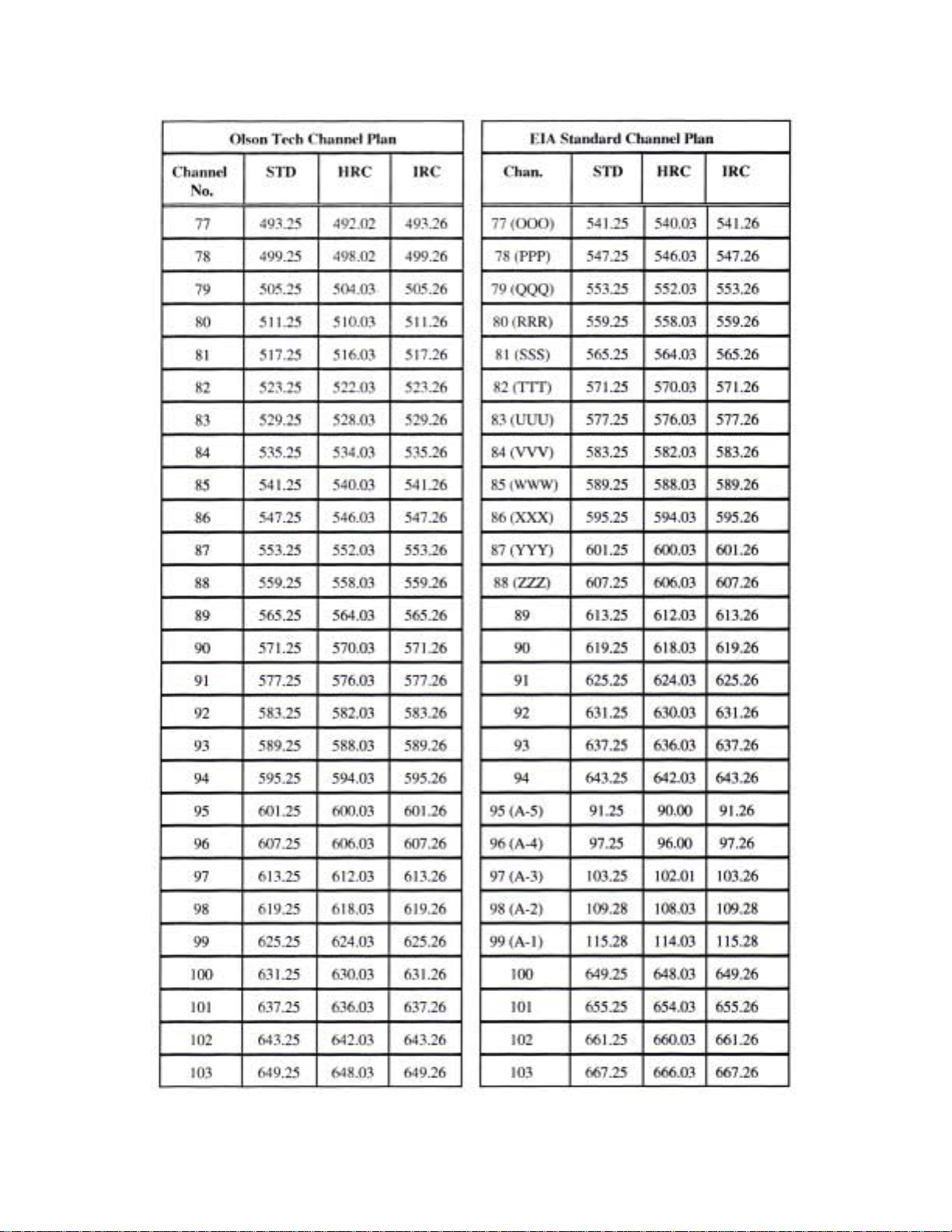
CHANNEL PLANS
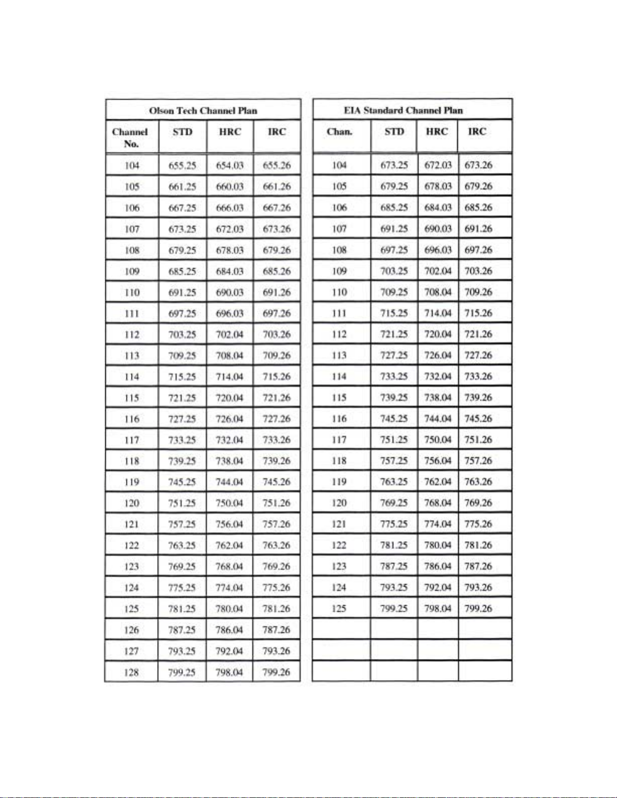
Frequencies shown are rounded to 2 decimal places. 121.26 indicates a 12.5KHz off-set or 121.2625 assignment.
331.27 is actually 331.2750. The HRC frequencies are based on a harmonic of 6.0003MHz. The LCD-550 has
AFC that will tune to these offsets without any special adjustment.
025-000345 REV B
Page 9
Page 29
025-000345 REV B
Page 10
Page 30
025-000345 REV B
Page 11
Page 31
025-000345 REV B
Page 12
Page 32
025-000345 REV B
Page 13
Page 33

INTRODUCTION
The LCD-550 is a small low cost demodulator for use in cable and off-air applications. It is designed to mount
in Olson T echnology’s LCM-550-RKA rack mountable chassis. The demodulator is shipped as a single LCD-550
and occupies 3 slots in the LCM-550 RKA chassis.
The LCD-550 can be made into a dual demodulator assembly by removing the front panel and guide pin on the
second LCD-550 and installing on top of the first demodulator .
The units have a front panel switch that switches between NTSC broadcast channels and a user defined CA TV
tuning mode. The user can select from 6 NTSC channel plans and frequency tuning.
The units have a single RCA type audio output connector . The type of signal at this connector is selected from
3 types by internal jumpers. The user can choose normal audio, multiplex audio, or subcarrier. RF Input and V ideo
Output connectors are “F” type. See Figure 2 for connector location.
The demods have an LED that indicates low input levels. This LED also flashes with invalid tuning settings.
(LED is labeled “NO VIDEO” on some early models)
INST ALLATION
Units are shipped in the Olson T ech CATV tuning mode with normal audio output. If other settings are
required, go to page 4 for instructions.
Slide the unit into the rack shelf, making sure that the notch on the rear of the unit engages the tab on the shelf.
Install and tighten the front thumb screw .
Connect the Audio and V ideo Output cables and the RF Input cable. Note that the combiner on the rear of
some LCM-550 rack shelves is for outputs, not inputs. It is recommended that units be added with the rack assembly
powered down, but they can be added hot as long as the long ground pin makes contact first. Connect the power
cable(s).
Set the tuning switches to the desired channel. If the unit is driving an LCM-550 with normal audio, no
internal adjustments will be required. See Figure 1 for front panel controls.
025-000345 REV B
Page 3
Page 34
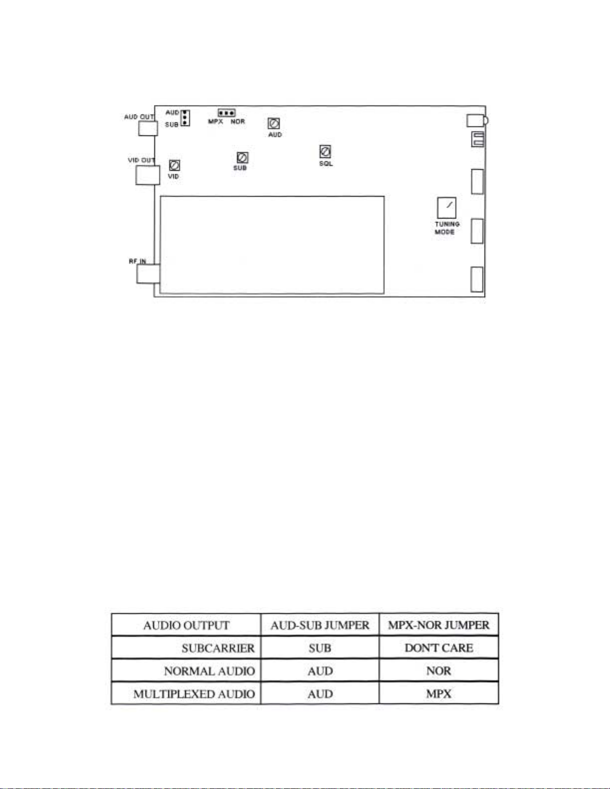
INTERNAL CONTROLS
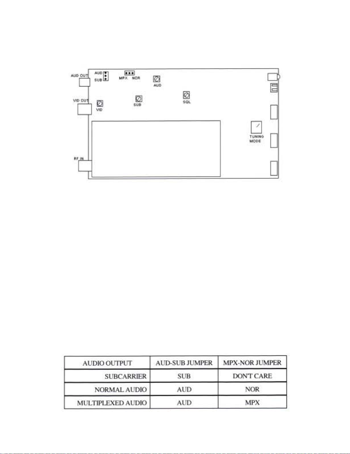
Refer to the following figure for the location of the internal controls
Figure 2
The VID pot sets the video output level. The video level should be measured into a 75ohm load.
The SUB pot sets the subcarrier output level. It does not affect the audio level.
The AUD pot sets the audio output level in both the normal and multiplex modes. It may need adjustment when
changing between normal and multiplex outputs.
The SQL pot sets the low RF level where the outputs are squelched.
There are two jumpers that select the type of audio output. The AUD-SUB jumper selects between subcarrier
and baseband audio outputs. If this jumper is in the AUD position, then the MPX-NOR jumper selects the type of
baseband audio output.
The NOR position is normal audio output. In the MPX position, the audio de-emphasis is disabled. This is
used for multiplex BTSC stereo. In the multiplex mode, the audio pre-emphasis on the associated modulator should
also be disabled
025-000345 REV B
Page 6
Page 35

LCD-550 PAL D/K
LOW COST AGILE
TELEVISION DEMODULATOR
INSTRUCTION MANUAL
Phone:
E-Mail: [email protected]
025-000350 REV B 8/06/01
(209) 586-1022
(800) 545-1022
Fax:
(209) 586-1026
www.olsontech.com
Page 36
025-000350 REV B
Page 10
Page 37

CAUTION!
USE CARE WHEN CHANGING CHANNELS OR MAKING ADJUSTMENTS TO THE
LCD-550 MODULES
These units are very small and they use smaller (and more delicate) components than are normally found in larger
equipment.
The DIP switch levers can be damaged by excessive force. Use a small pointed object to gently move the switch levers
to the required positions.
The rotating controls can be pushed-in and broken if too much force is applied against them. When adjusting these
controls, use caution and an alignment tool in good condition that is a good fit to the control slot.
025-000350 REV B
Page 2
Page 38

INTRODUCTION
The LCD-550 is a small low cost demodulator for use in cable and off-air applications. It is designed to mount
in Olson T echnology’s LCM-550-RKA rack mountable chassis. The demodulator is shipped in both single (LCD550X1) and dual (LCD-550X2) versions. Both versions occupy 3 slots in the LCM-550 RKA chassis.
The units have a single RCA type audio output connector . The type of signal at this connector is selected from
3 types by internal jumpers. The user can choose normal audio, multiplex audio, or subcarrier. RF Input and V ideo
Output connectors are “F” type. See Figure 2 for connector location.
The demods have an LED that indicates low input levels. This LED also flashes with invalid tuning settings.
(LED is labeled “NO VIDEO” on some early models)
INST ALLATION
Units are shipped in the + .25MHz frequency tuning mode with normal audio output. P AL versions tune by
frequency only with three front panel rotary switches. If other settings are required, go to page 4 for instructions.
Slide the unit into the rack shelf, making sure that the notch on the rear of the unit engages the tab on the shelf.
Install and tighten the front thumb screw .
Connect the Audio and V ideo Output cables and the RF Input cable. Note that the combiner on the rear of
some LCM-550 rack shelves is for outputs, not inputs. It is recommended that units be added with the rack assembly
powered down, but they can be added hot as long as the long ground pin makes contact first. Connect the power
cable(s).
025-000350 REV B
Page 3
Page 39
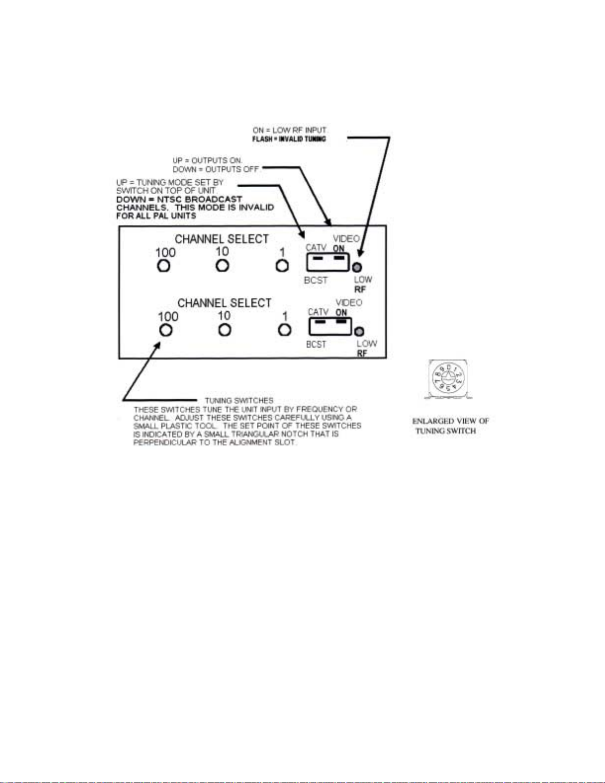
FRONT PANEL CONTROLS
Front panel controls should be adjusted only with plastic alignment tools. Damage may result if metal tools
are used. Refer to the following figure for location of the front panel controls.
FIGURE 1
The LOW RF LED turns on with low or missing RF input. It also flashes on invalid tuning or mode settings. All
outputs are squelched with low RF or invalid tuning.
The VIDEO ON dipswitch turns all outputs on and off.
The CA TV-BCST dipswitch changes the tuning mode. In the CATV position the tuning mode is set by the
tuning mode switch on the top of the demod. The BCST mode tunes NTSC broadcast VHF/UHF channels.
This mode is invalid for all P AL units.
The channel select switches tune the RF input frequency . The set point of these switches is indicated by a
small triangular notch that is perpendicular to the adjustment slot. When tuning by frequency , these switches
are the frequency in MHz, with the .25MHz steps set by the tuning mode switch.
025-000350 REV B
Page 4
Page 40
OPERATION
Most adjustments require removing the top cover. T o access the bottom unit in a dual (X2) version, remove
the 2 screws holding the top demod to the front panel. T o access the internal adjustments, it is not necessary to remove
the demod from the front panel; just remove the top cover screws. Figure 2 shows the adjustment locations. When all
adjustments are complete, replace the top cover. For X2 units, repeat this process for the top unit.
MODE SWITCH
This switch selects the CA TV tuning mode. It is accessed through a hole in the top cover . Only positions
6-9 are valid settings on P AL units. Positions 0-2 select traditional channel plans. Positions 3-5 select EIA stan-
dard channel plans. Positions 6-9 select direct frequency tuning.
025-000350 REV B
Page 5
Page 41
INTERNAL CONTROLS
Refer to the following figure for the location of the internal controls.
FIGURE 2
The VID pot sets the video output level. The video level should be measured into a 75ohm load.
The SUB pot sets the subcarrier output level. It does not affect the audio level.
The AUD pot sets the audio output level in both the normal and multiplex modes. It may need adjustment when
changing between normal and multiplex outputs.
The SQL pot sets the low RF level where the outputs are squelched.
There are two jumpers that select the type of audio output. The AUD-SUB jumper selects between subcarrier and
baseband audio outputs. If this jumper is in the AUD position, then the MPX-NOR jumper selects the type of
baseband audio output.
The NOR position is normal audio output. In the MPX position, the audio de-emphasis is disabled. This is used
for multiplex BTSC stereo. In the multiplex mode, the audio pre-emphasis on the associated modulator should also
be disabled
025-000350 REV B
Page 6
Page 42

TROUBLESHOOTING
No output, low RF LED on:
RF input low or absent.
Incorrect tuning mode or channel.
Check the small triangular notch for switch settings.
No output, low RF LED flashes:
Invalid tuning. Check tuning and mode switches. P AL units tune by frequency only . Broadcast channel
mode is also invalid for P AL.
Video output very high contrast and distorted:
V ideo output is unterminated.
Video output washed out:
V ideo output is double terminated.
Audio problems:
V erify correct jumper settings. Pre-emphasis setting on modulator must
match that of demodulator .
025-000350 REV B
Page 7
Page 43

LCD-550 P AL D/K SPECIFICA TIONS
RF Input .......................................
RF Input Level ..............................
V ideo Output ................................
V ideo Performance .......................
Audio Output T ypes ......................
Audio Output ................................
MPX Audio Output .......................
Audio Subcarrier Output ...............
P AL D/K 49.75 to 863.25MHz
Off-air -10dBmV to +25dBmV
CA TV -10dBmV to +10dBmV
1V p-p +/- 5 IRE into 75 Ω
Diff. gain < 5%
Diff. phase < 3°
Normal Audio
Multiplex Audio
Subcarrier
(selected by internal jumpers)
500 mV p-p into 600 Ω unbalanced
500 mV p-p into 600 Ω unbalanced
> +40dBmV into 75 Ω unbalanced
Front Panel Controls .....................
Front Panel Indicator .....................
Rear Panel Connectors ..................
Power Requirements .....................
Size ..............................................
W eight ..........................................
Output on/off
CA TV/Broadcast (only CATV is valid on P AL units)
Rotary tuning switches
Low RF
RF in, V ideo out...type “F”
Audio...RCA
< 2 watts from LCM-550 RKA chassis
(5V @ 165mA and 10V @ 30mA typical)
1.3x3x6
< 1 lb.
025-000350 REV B
Page 8
Page 44
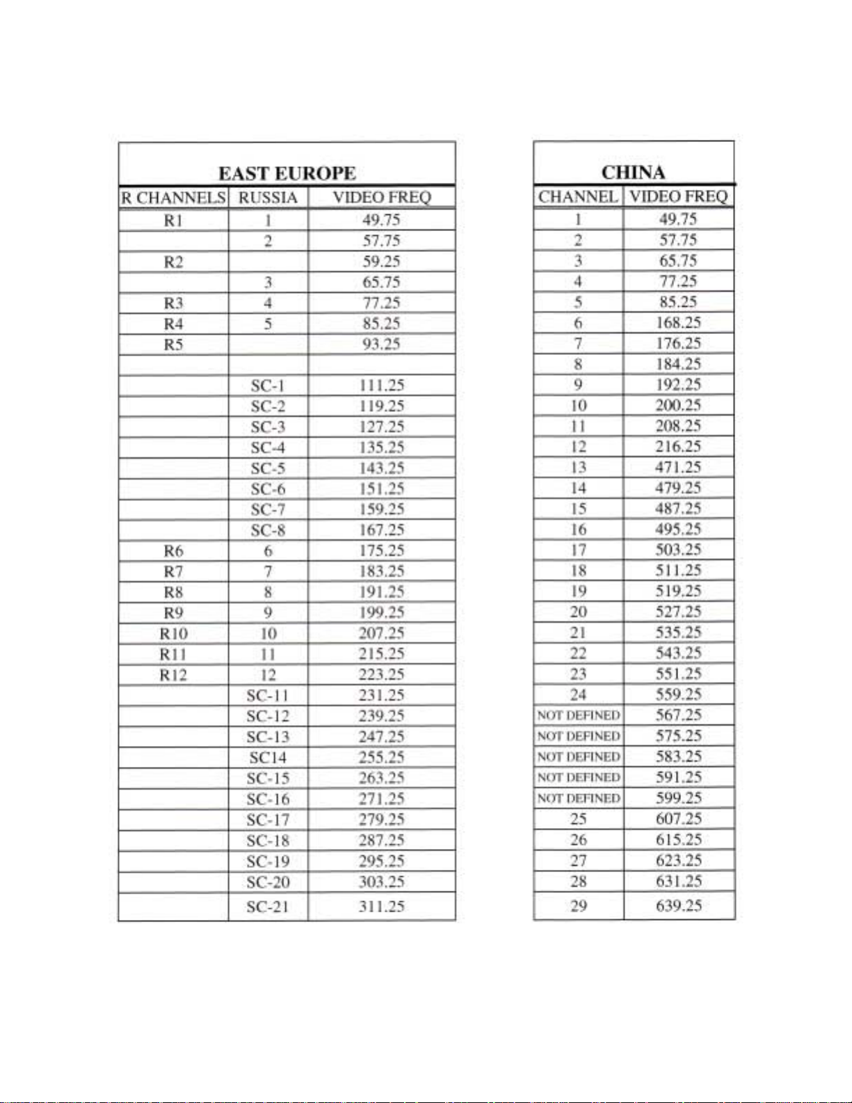
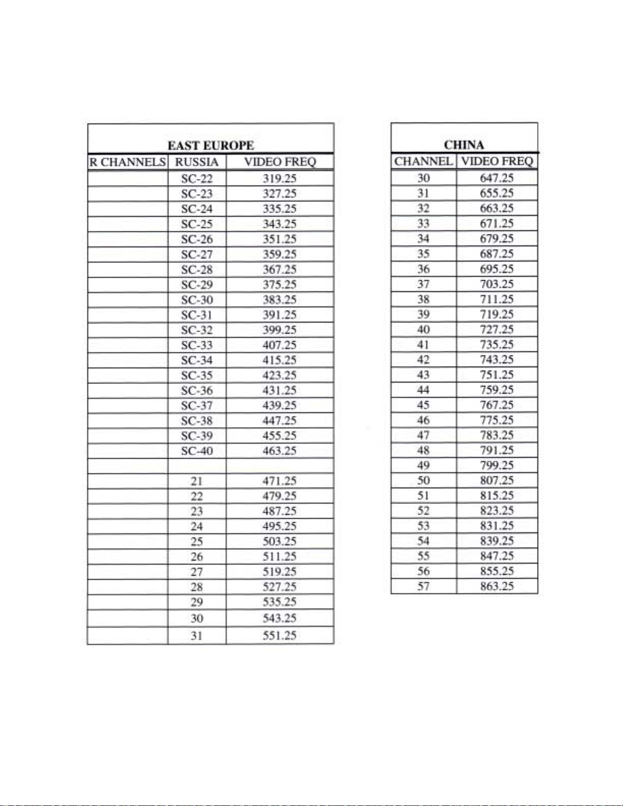
P AL D/K Channels
025-000350 REV B
Page 9
Page 45

LCM-550x12 AMPLIFIER
55 TO 870MHz DISTRIBUTION AMPLIFIER
INSTRUCTION MANUAL
Phone:
E-Mail: [email protected]
025-000354 REV . A 6/25/01
(209) 586-1022
(800) 545-1022
Fax:
(209) 586-1026
www.olsontech.com
Page 46

LCM-550x12
55 to 870MHz DISTRIBUTION AMPLIFIER
1) INTRODUCTION
The Olson T echnology Inc. LCM-550x12 Series Amp is a high performance 55 to 870MHz distribution amplifier
designed to work with the output of the 12-port combiner. It is easily attached to the back of the LCM-550x12
chassis by two thumb screws. It will provide +45dBmV of output per channel when connected to the output of the
12 port combiner .
This amplifier is powered from the LCM-550x12 power supply and it includes the required D.C. power interconnect harness. Also included with this amplifier is a cable to connect the 12 port combiner output to the amplifier
input.
2) INST ALLA TION
A) Attach the amplifier to the vertical lip at the rear of the LCM-550x12 chassis. The lip of the chassis
fits into the slot at the bottom of the amplifier. The RF Output and T est Point connection should face
to the rear. Loosen the two thumbscrews to allow the amplifier to sit all the way down on the shelf
lip. Center the aplifier left to right and tighten the thumbscrews firmly to hold it in place.
B) Locate the D.C. power harness on the LCM-550x12 intended for the eighth module position
(counting from the left side). If the harness is connected to a module, unplug it.
Plug this harness into the 4-pin power connector on the amplifier. Note that the connector is keyed
to aid in plugging it in properly , but it CAN be forced on upside down. When correct, the RFD wire
is in the TOP position. Do not plug it in upside down.
The D.C. power harness permanently attached to the amplifier is intended to provide power to the
eighth module position. If there is a module in the eighth position that was disconnectd earlier,
connect this harness to it. Use the same caution as above to insure that the connector is not plugged
in upside down. Note that on the modulator module, the redwire is on the BOTTOM.
C) Connect the provided RF cable between the combiner RF out and the amplifier RF input. Use
caution not to damage or bend the small center conductor of this cable.
025-000354 REV . A Page 2
Page 47

3) OPERA TION
The LCM-550x12 amplifier is the designed to operate at +45 dBmV out with 12 channels. Measure the
direct output of the amplifier with a spectrum analyzer or signal level meter . Adjust the output level controls
on the individual modulators for your desired operational levels. Exceeding the specified +45 dBmV
maximum output level (12 channels) may cause systems distortion levels to exceed acceptable levels. If all
of yo ur desired carrier levels are below +41 dBmV , Olson T echnology suggests that you use a fixed
attenuator pad between the combiner output and the amplifier input. Use a 3dB pad for maximum outputs
of 35-41 dBmV , a 6dB pad for 35-38, etc. Once the output levels are set, the amplifier may be connected
to its intended use and levels at its test point maybe measured and recorded for referance. If the amplifier
test point is used as a output, be sure that the main output is terminated in 75Ω.
4)4)
4) SPECIFICA TIONS
4)4)
Frequency ................................48MHz to 870MHz
Gain........................................ 22dB minimum
Gain V ariation..........................+1dB minimum
Input Return Loss.....................15dB minimum
Output Return Loss..................16dB minimum
CTB/CSO with 12 Carriers..... >65dB below 12 output carriers at +45dBmV
Power Requirments..................Operates from LCM-550x12 power supply . <4 watts
LCM-550x12
55 to 870MHz DISTRIBUTION AMPLIFIER
025-000354 REV . A Page 3
Page 48

LCM-550-FAC
TWEL VE-PORT COMBINER
FOR LCM-550X12 SERIES
INSTRUCTION MANUAL
Phone:
E-Mail: [email protected]
025-000354 REV . A 6/22/01
(209) 586-1022
(800) 545-1022
Fax:
(209) 586-1026
www.olsontech.com
Page 49

1) INTRODUCTION
The OLSON TECHNOLOGY LCM-550-F AC is a 12-port combiner with a frequency range of
50-550MHz. Although this combiner is capable of operation to 870MHz, it is not specified
beyond 550 MHz.
This field-installable combiner is designed to integrate with the LCM-550X12 Series system and mounts in
place of the blank front panel at the top of the unit. RF interconnect cables are provided to enable
connection to 12 modulator modules.
T welve inputs and the common RF output are at the rear of the unit. For convenience, the (nominal) –20dB
test point is accessible from the front of the unit.
T wo other 12-port combiners are available from OLSON TECHNOLOGY : These units mount in standard
19" equipment racks and are 1 rack-unit high. The OTHC-12 has a frequency range of 5MHz to 550MHz
and the OTHC-12-1G has a frequency range of 50MHz to 1000MHz.
LCM-550-FAC
TWEL VE PORT COMBINER
FOR LCM-550X12 SERIES
2) INST ALLA TION
If the LCM-550X12 Series system is mounted in an equipment rack, it must be removed or moved forward
enough to provide access to the four screws on each side that secure the top front panel.
Remove the screws that secure the top front panel and remove the panel.
Using the screws removed above, mount the combiner in place of the blank front panel. If necessary ,
reinstall the system in the equipment rack.
Connect the RF cables to the modulators as required. Use caution not to damage or bend the small center
conductors of these cables. The combined signals are available at the RF output connector.
3) OPERA TION
Connect a spectrum analyzer or signal level meter to the RF output and adjust the individual modulators as
required for the desired combined levels.
NOTE: This combiner has an insertion loss of between 17dB and 23dB. The LCM-550 modulators should
not be operated above +45dBmV . T ake these values into account when setting the output levels from the
combiner. If higher output levels are required, the OLSON TECHNOLOGY LCM-550X12 amplifier is
available. This amplifier mounts-to and is powered-by the LCM-550 Series system main chassis. It will
operate at +45 dBmV out with 12 channels.
Once the levels have been set, the levels at the test point may be measured and recorded for future
reference. Note that the RF output must be terminated in 75Ω when making these test point measurements.
025-000354 REV . A Page 2
Page 50

4) SPECIFICA TIONS
FREQUENCY.................................................50MHz to 550MHz
INSER TION LOSS.........................................20 +3.0dB
TEST POINT LOSS........................................20
+3.0dB
POR T-TO-POR T ISOLA TION.......................35dB Minimum
RETRUN LOSS..............................................13dB Minimum
CONNECTOR................................................T ype “F” - (ALL)
025-000354 REV . A Page 3
 Loading...