

Page 1

OTFM-1000
FM MODULA TOR
INSTRUCTION MANUAL
Phone:
E-Mail: [email protected]
(209) 586-1022
(800) 545-1022
Fax:
(209) 586-1026
www.olsontech.com
Page 2

OTFM-1000
Frequency Agile Audio FM Modulator
The OTFM-1000 is designed for audio applications in the FM band from 88MHz to 108MHz. This design offers
constant deviation regardless of frequency setting. With the change of one internal jumper pin, the unit becomes
stereo compatible.
SPECIFICA TIONS
Output Frequency Range................................
Frequency Stability/Accuracy ..........................
Output Power Level.......................................
Spurious Output.............................................
Deviation........................................................
Audio Input Level...........................................
Audio Input Connector...................................
MPX Input Connector....................................
RF Output Connector .....................................
Power Requirments........................................
88MHz to 108MHz - Front panel DIP switch selectable in 0.1MHz
increments.
+ 5KHz maximum from selected output carrier.
+40dBmV minimum. Adjustable downward by 10dB minimum by
front panel control.
>60dB below output carrier level.
150KHz - 75 µ pre-emphasis internal selectable.
0.5V p-p audio input for 150KHz deviation.
Screw terminals
T ype F
T ype F
115 V AC @60Hz - 10 watts maximum.
Size................................................................
19” rack mount. 1.75” H x 8” D
Page 2
Page 3
OTFM-1000 FM MODULATOR
1) The Olson T echnology OTFM-1000 FM Modulator is designed for use in the DM spectrum of 88MHz to
108MHz. The unit is selectable in .1MHz increments across the complete spectrum and has constant
deviation at any frequency in the spectrum.
2)
3)
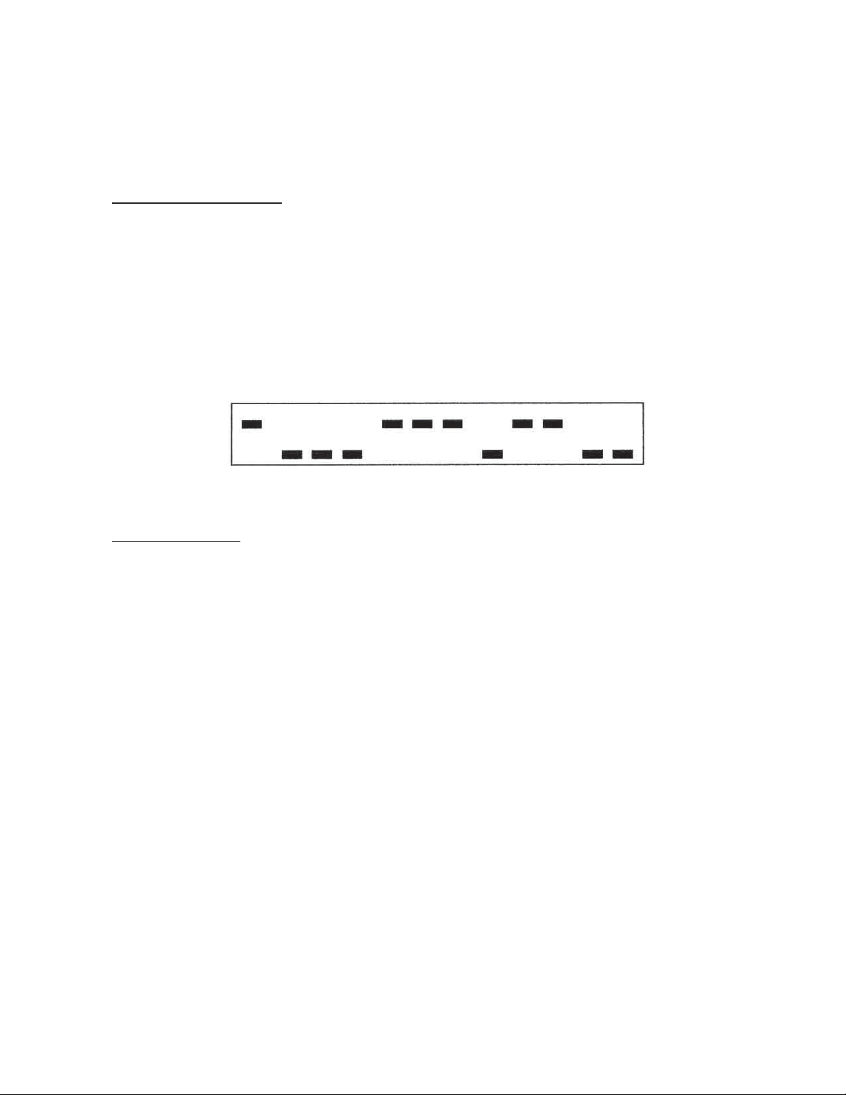
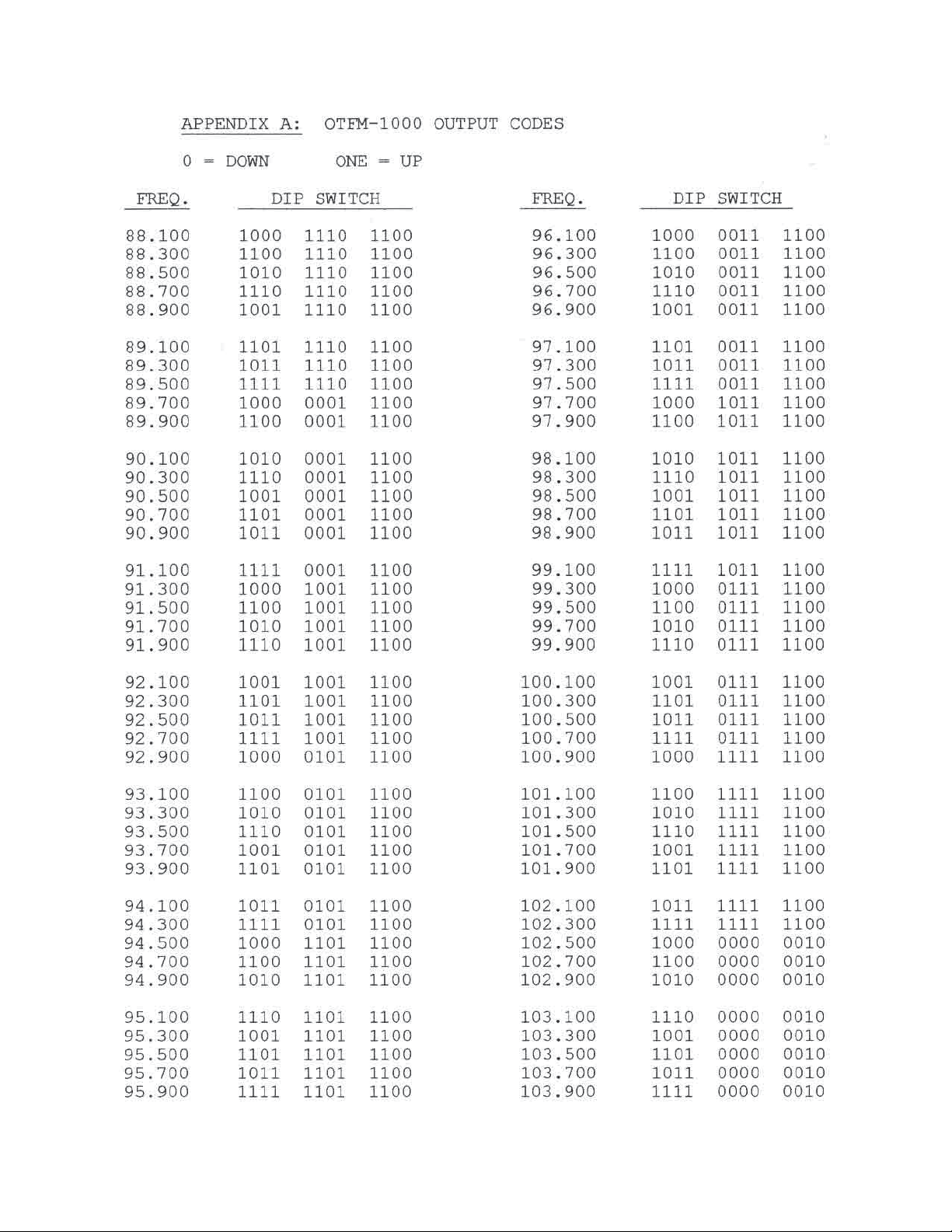
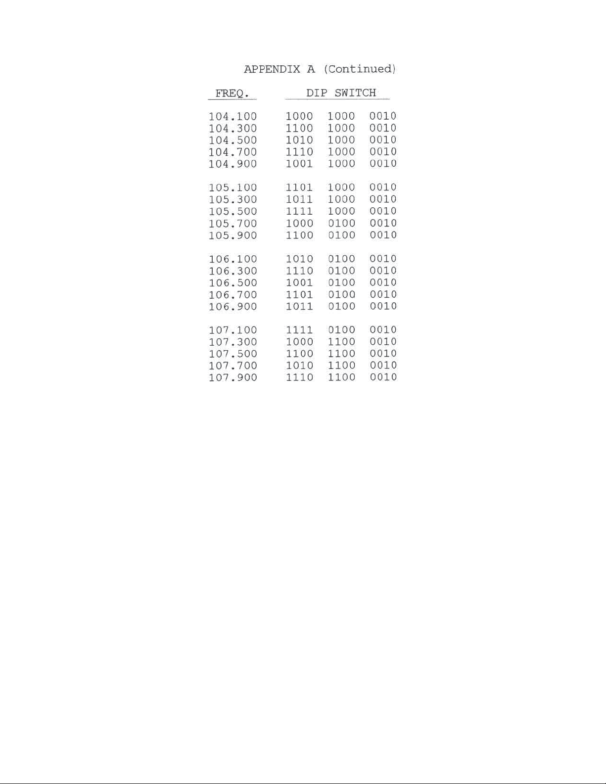
Output Frequency Select - Remove the front panel cover plate to expose the DIP switches. Appendix A
is a list of all DIP switch codes for output frequencies at odd intervals, ie: 88.1, 88.3, etc.
T o select other frequencies at “even” intervals, utilize the chart to select the nearest “odd” frequency above
the frequency desired. Placing the first DIP switch in the down position (left hand switch) will lower the
frequency by .1MHz.
Example: 88.0MHz is desired frequency
A) Select closest frequency above 88.0MHz from chart which is 88.1MHz.
B) Move first switch to down position to subtract 0.1MHz and yield 88.0MHz.
Modulation Adjust - Connect the baseband audio signal to the audio input terminal on the rear panel.
Adjust the “modulation adjust” control on the front panel until the overmod light just begins to blink on.
Modulation should be set during periods of active audio (music, etc). Attempting to set the modulation
during quiet periods can result in over-modulation.
4) The maximum output power level from the unit is +40dBmV (RF output adjust full CW). T o reduce the
level, turn the RF adjust pot CCW until desired level is obtained.
5) Balanced or unbalanced input is selected with internal jumper plug W1. Pre-emphasis in or out is selected
with W2. Remove the top cover to gain access to W1 and W2. These are located in the left rear area of
the main PCB.
A) This unit is shipped with W1 in the balanced position. The jumper plug is shorting two pins nearest the
rear panel. T o ground the left input terminal or the MPX input, move the jumper plug to short two pins
on W1 nearest the front panel.
B) T o defeat the pre-emphasis, remove the jumper plug on W2. Pre-emphasis is used for mono only and is
defeated when MPX stereo is used.
6) “Audio In” and “MPX In” are terminated with 620 internally . For high impedance input, cut resistor from
“Audio In” terminals inside.
Page 3
Page 4
Page 4
Page 5
Page 5
 Loading...