

Page 1
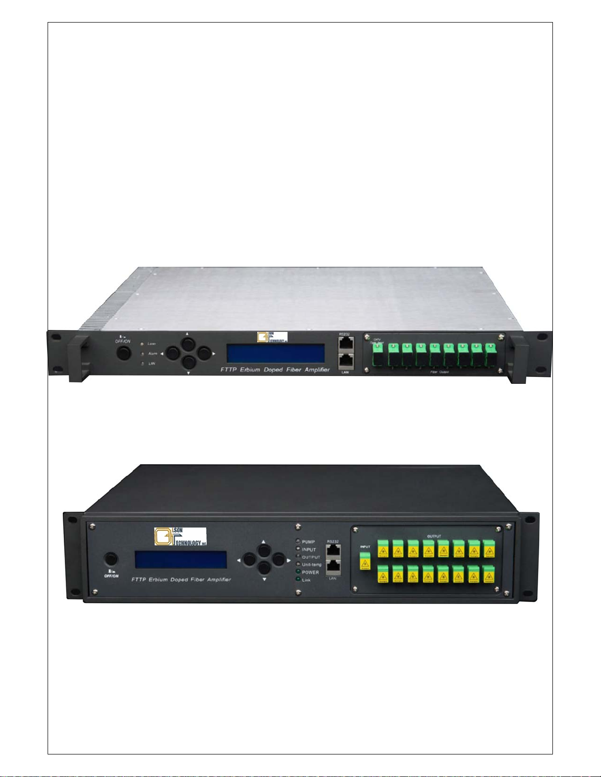
HHiigghh--PPoowweerr
11555500nnmm EErrbbiiuumm DDooppeedd FFiibbeerr AAmmpplliiffiieerr
OOTTEEB
OOPPEERRAATTIIOONN MMAANNUUAALL
1RU Model - Combined Output Power up to 1,000mW (+30dBm)
B--CCLL--BB SSeerriieess
2RU Model - Combined Output Power up to 5,000mW (+37dBm)
025-000634X1 Subject to Change Without Notice 13 Mar 2013
Page 2

CONTENT
1.0 PRODUCT SUMMARY........................................................................ 1
2.0 INSTALLATION................................................................................ 1
2.1 Unpacking ...................................................................................... 1
2.2 EDFA Mounting and Power Connection ................................................ 1
2.3 Optical Connection........................................................................... 1
3.0 EDFA CONTROLS, INDICATORS, AND ALARMS ................................. 3
3.1 The operation of the panel ................................................................ 3
4.0 PORT AND CABLE ASSIGNMENTS..................................................... 5
4.1 Management Port (RJ-45) ................................................................. 5
4.2 RS-232 Console port (DB9)............................................................... 8
4.3 Power Connection ............................................................................ 8
5.0 FAULTS ........................................................................................... 9
5.1 Warning status................................................................................ 9
5.2 Alarm status ................................................................................... 9
5.3 Fault prevention .............................................................................10
025-000634X1 Subject to Change Without Notice
Page 3

1.0 PRODUCT SUMMARY
The OTEB-CL-B series high-power, single-mode EDFA is characterized by low noise and high
linearity. It offers a flexible, low-cost solution for large area distribution. The OTEB-CL-B series
incorporates advanced design techniques for heat dissipation, which assures reliability and
stable operation of the PUMP laser(s). RS-232 and RJ-45 on the front panel offer serial com-
munication and SNMP network interface. The LCD displays all the parameters of the unit and
alarms. The laser will be automatically switched off if the optical input power is too low.
Total Output Power Capability (1RU & 2RU Models)
OTEB-CL-B: 1RU chassis, total output power >1000mW, offers up to 16 optical outputs.
OTEB-CL-B: 2RU chassis, total output power >5000mW, offers up to 64 optical outputs.
2.0 INSTALLATION
2.1 Unpacking
Inspect the shipping boxes for any obvious damage.
Unpack the unit.
Inspect the appearance of the unit for any shipping damage.
Document and inform the shipping company, if any damage is found.
Save the shipping boxes and their inserts for future shipment in case the product needs
repair.
NOTE: When shipping the EDFA back to the manufacturer, the manufacturer does not
accept responsibility for the damage caused by non-use the original packaging.
2.2 EDFA Mounting and Power Connection
1. Place the unit into a 19-inch wide rack or cabinet. Make sure to leave a 1.75-inch (1RU)
space above and below the unit for cooling.
2. The OTEB-CL-B series 1550nm EDFA operates at temperatures between 0°C to +50°C
(+32°F to +122°F). We recommend +25°C (+77°F) environment temperature. Humidity
is 95% maximum (non-condensing conditions). We recommend operating in a dust-free
environment.
3. The equipment can be powered by AC or DC. Power supply requirements:
AC input 94-245V
, 50-60Hz
AC
DC input 36-60VDC, floating
Power consumption (Max) 50W (1RU), 150W (2RU)
The EDFA must have good grounding with grounding resistance <4Ω.
2.3 Optical Connection
Clean all fiber patch cords before connecting to the EDFA. Optical Input is nominally -7dBm to
+7dBm. In some cases it is usable from -10dBm to +10dBm, but an alarm may be indicated.
ALWAYS be SURE that all power is removed from the EDFA before optical connectors
are mated or unmated. Eye damage and EDFA damage may result if the EDFA is
powered while connectors are cleaned or mated/unmated.
025-000634X1 Page 1 of 11
Page 4
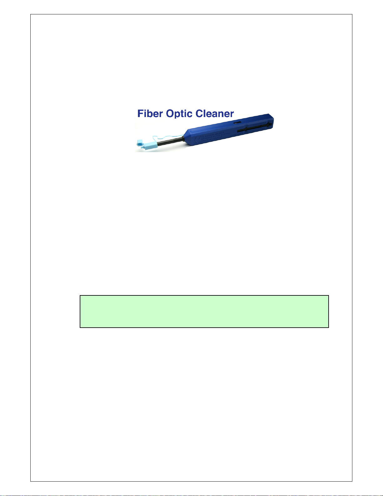
Cleaning Guidelines:
Fiber Patch cord connectors
- Remove the dust cap of the fiber connectors and clean the fiber connector tip with a
high-quality fiber cleaner such as the Senko Fiber Optic Cleaner (shown below). Check if
there are scratches or debris on the connector surface by using a microscope (400X
magnification recommended).
- If no scratches or debris is found, the connector is ready for connection. If scratches or
debris is found, repeat the fiber patch cord connector cleaning. Severe scratches may
require replacing the connector.
Fiber Bulkhead Connectors
- Compressed air may be used to clean fiber bulkhead connectors. Use compressed air
according to the following minimum specifications:
- Non-residue, inert gas for precision dust removal
- Ultra-filtered to < 0.2 microns
- Recommended for optical systems
- Using compressed air as listed above, remove the bulkhead dust cover and hold the can
of compressed air about 6 inches away from the connector. After spraying a few short
bursts into the bulkhead, the connector is clean and ready for connection.
- If compressed air is not available, the transmitter fiber bulkhead connector may be
cleaned by 2.5 mm alcohol-saturated sponge.
CAUTION: Use caution when handling fibers.
Do not exceed fiber manufacturer’s pulling tension or bend radius specifications
when removing fiber bulkhead connector plate.
2. Make sure the laser key switch on the front panel of the transmitter is in the OFF position.
3. Connect a fiber to the EDFA input. Attach the other end of that fiber to a 1550nm
transmitter with optical output in the +3dBm range. Power up that transmitter once the
fiber connections to the EDFA input are secure.
4. Connect a fiber patch cord from the output of the transmitter to the optical power meter.
Be sure the optical power meter is rated for the optical power level expected at the EDFA
output.
5. Turn the transmitter laser key switch to the ON position.
6. NEVER disconnect any fiber connections to the EDFA while it is powered.
7. Use the optical power meter to verify that the transmitter optical power meets the
specification.
8. Turn the transmitter laser key switch to the OFF position.
025-000634X1 Page 2 of 11
Page 5
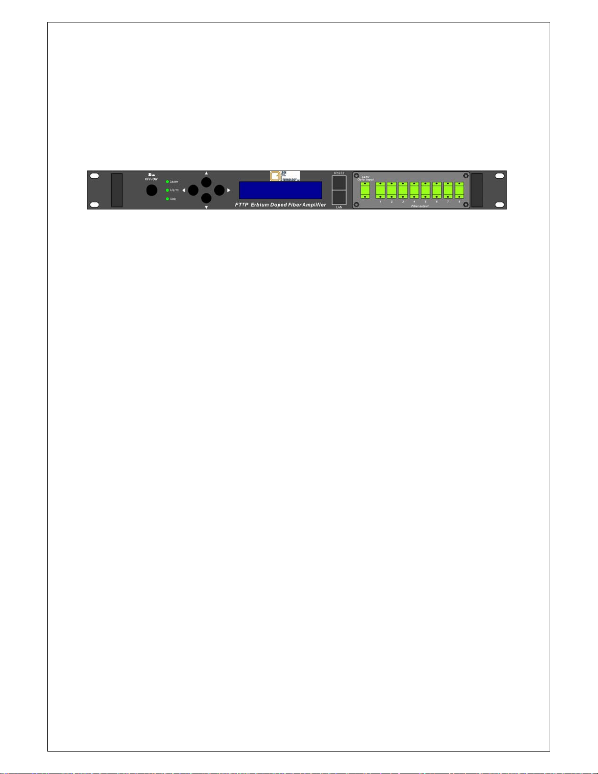
3.0 EDFA CONTROLS, INDICATORS, AND ALARMS
This section of the manual will give an overview of the available menus in the OTEB-CL-B series
EDFA and their descriptions. The user can scroll through the EDFA menus by using the push
buttons that are on the front panel and are located beside the LCD screen.
OTEB-CL-B (1RU Style)
3.1 The Operation of the Panel
3.1.1 Starting Menu
A. Plug in the power supply and connect all fibers.
B. Turn on power switch in the back panel, Front panel display “KEY OFF”
Laser Status LED Red
Alarm Status LED Green
Link Status LED Off / Green
C. Apply optical input power, then press laser start-up key switch. Front panel
shows “KEY ON”,Laser status lamp turns green from red.
3.1.2 Start-up Main Menu
Press ▲/▼ button and the following menu will be displayed in sequence.
Menu #1 - Model Displays the model of this equipment
Menu #2 - S/N Displays the serial number of this equipment
Menu #3 - INPUT Displays the input optical power in dBm.
Menu #4 - OUTPUT Displays the output optical power in dBm.
Menu #5 - BIAS1 Displays the current of PUMP1
Menu #6 - BIAS2 Displays the current of PUMP2
Menu #7 - BIAS3 Displays the current of PUMP3
Menu #8 - BIAS4 Displays the current of PUMP4
Menu #9 - BIAS5 Displays the current of PUMP5
Menu #10 - BIAS6 Displays the current of PUMP6
Menu #11 - BIAS7 Displays the current of PUMP7
Menu #12 - BIAS8 Displays the current of PUMP8
Menu #13 - BIAS9 Displays the current of PUMP9
Menu #14 - TEC1 Displays the TEC current of PUMP1
025-000634X1 Page 3 of 11
Page 6

Menu #15 - TEC2 Displays the TEC current of PUMP2
Menu #16 - TEC3 Displays the TEC current of PUMP3
Menu #17 - TEC4 Displays the TEC current of PUMP4
Menu #18 - TEC5 Displays the TEC current of PUMP5
Menu #19 - TEC6 Displays the TEC current of PUMP6
Menu #20 - TEC7 Displays the TEC of PUMP7
Menu #21 - TEC8 Displays the TEC current of PUMP8
Menu #22 - TEC9 Displays the TEC current of PUMP9
Menu #23 - TEMP1 Displays the laser temperature of PUMP1
Menu #24 - TEMP2 Displays the laser temperature of PUMP2
Menu #25 - TEMP3 Displays the laser temperature of PUMP3
Menu #26 - TEMP4 Displays the laser temperature of PUMP4
Menu #27 - TEMP5 Displays the laser temperature of PUMP5
Menu #28 - TEMP6 Displays the laser temperature of PUMP6
Menu #29 - TEMP7 Displays the laser temperature of PUMP7
Menu #30 - TEMP8 Displays the laser temperature of PUMP8
Menu #31 - TEMP9 Displays the laser temperature of PUMP9
Menu #32 - +5V Monitor Displays the voltage
Menu #33 - -5V Monitor Displays the voltage
Menu #34 - UNIT TEMP Displays the unit's case temperature
Menu #35 - IP Displays the IP address (Adjustable)
Menu #36 - SUBNET Display the address of net mask (Adjustable)
Menu #37 - GATEWAY Displays the gateway address (Adjustable)
Menu #38 -
TRAP ADDR1 Displays the TRAP1 address (Adjustable)
Menu #39 - TRAP ADDR2 Displays the TRAP2 address (Adjustable)
2.1.1 Changing Parameters
Press the ▼ key to select the address menu to be updated. Press the key to choose the
change place. Push the
key to increment the value by one. Press the ▼ key to the exit the
address and save it.
For example, update the IP setup menu, IP: 192.168.000.015; to change 5 to 6, use the
to choose the number 5, then press the
key to change 5 to 6. Finally, press the ▼ key to
save updated IP: 192.168.000.016
key
025-000634X1 Page 4 of 11
Page 7
4.0 PORT AND CABLE ASSIGNMENTS
OTEB-CL-B series provide the following management ports:
RS-232 port: Suitable for examining OTEB-CL-B parameters and some system configuration.
SNMP: Simple network management protocol.
Before connecting to one of the OTEB-CL-B series ports, please read the following
instructions and port connectivity requirements.
4.1 Management Port (RJ-45)
4.1.1 Port Description
The OTEB-CL-B series management port connector type is RJ-45.
8
11
8
Figure 4.1.1 RJ–45 Connector Plug and Socket
The Management port (RJ-45) can be connected to any device that uses a standard network
interface (e.g., a workstation, server, bridge or router). The RJ-45 connector can be
connected with similar network equipment (i.e. a network Hub). Use unshielded twisted-pair
(UTP) or shielded twisted-pair (STP) cable for RJ-45 connections: 100-Ohm Category 3, 4 or
5 cable for 10 Mbps connections or 100-Ohm Category 5 cable for 100 Mbps connections. The
maximum allowable cable length is 100 meters.
4.1.2 Pin assignment
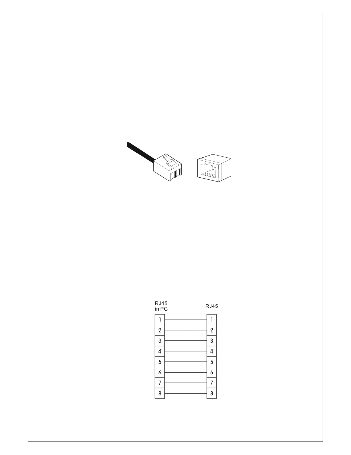
When the network management cable (RJ-45 connector in each side) connects NMS PC and
OTEB-CL-B series directly, use a straight cable. See Figure 4.1.2.
Figure 4.1.2 RJ-45 Connector Straight-Through Connection
025-000634X1 Page 5 of 11
Page 8
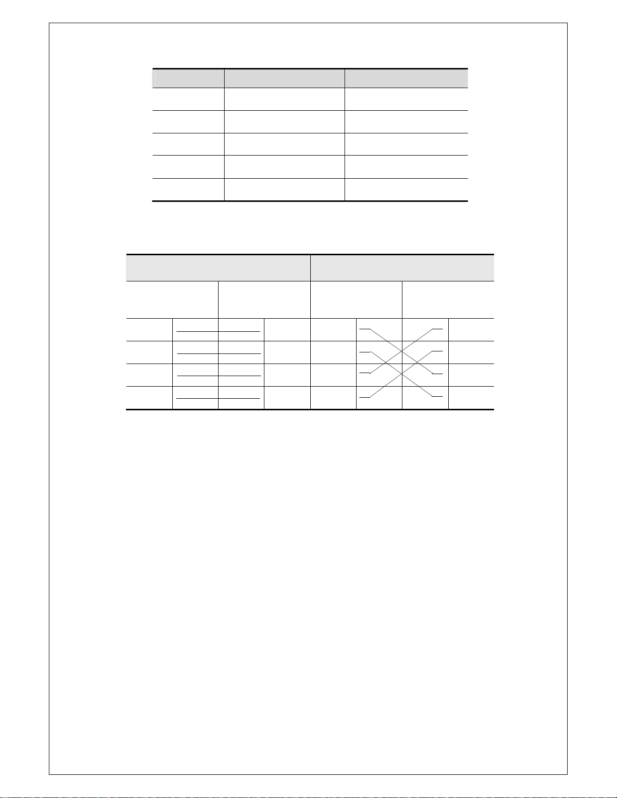
PIN Workstation port MDI
1 Input receive data+ Output transmit data+
2 Input receive data- Output transmit data-
3 Output transmit data+ Input receive data+
6 Output transmit data- Input receive data-
4, 5, 7, 8 Unused Unused
Table 4-1 RJ-45 Pin Assignment
Straight Cross
(OTEB-CL-B) (Adapter) (OTEB-CL-B) (HUB/
OTEB-CL-B)
1 IRD+ 1 OTD+ 1 IRD+ 1 IRD+
2 IRD- 2 OTD- 2 IRD- 2 IRD-
3 OTD+ 3 IRD+ 3 OTD+ 3 OTD+
6 OTD- 6 IRD- 6 OTD- 6 OTD-
Table 4-2 Straight and Cross-Cable Connection
025-000634X1 Page 6 of 11
Page 9

4.1.3 Port Connection
OTEB-CL-B series automatically detects the Ethernet cable type (Straight-through or
Crossover), so either type can be used. An Ethernet twisted pair cable should be
connected between the RJ-45 connector of the OTEB-CL-B series and any device with
a standard network interface (such as a work station or server), or to a network
interconnection device (such as a bridge or router).
1) Ensure that the device to be connected has a 10BASE-T or 100BASE-TX network
interface card (NIC).
2) Prepare a twisted pair Ethernet cable with RJ-45 plugs on each end. Use Cat 3, 4
or 5 cable for standard 10Mbps Ethernet connections, or Cat-5 cable for 100Mbps
Fast Ethernet connections.
3) Plug one end of the cable into the computer's NIC and plug the other end into any
RJ-45 port of the OTEB-CL-B series. The OTEB-CL-B RJ-45 port supports both
10Mbps and 100Mbps Ethernet connections. Ensure that the plug's locking tab
clicks into proper position.
Caution: Do not plug a phone jack connector into the RJ-45 port. This may
damage the EDFA. Instead, use only twisted-pair cables with RJ-45 connectors
that conform to FCC standards.
Note:
1) Connect other compatible OTEB-CL-B series or network hub, use direct or
cross-connect cable to connect to the RJ-45 port in other device.
2) Ensure that the twisted pair cable length does not exceed 100 meters.
3) Cat-5 cable is recommended for all network connections to avoid confusion or
inconvenience, when upgrading to Fast Ethernet devices in the future.
4) Cascade length provision: IEEE 802.3 standard prescribes that at most four hubs
(such as repeaters) can be cascaded.
4.1.4 Connection Management (Out-Band)
Remote management can be performed through the dedicated Management port
(10/100BASE-TX port) on the front of the OTEB-CL-B or any 10/100BASE port of
OTEB-CL-B.
Before the Management port is accessed through the LAN port, please configure the
IP address and subnet mask by serial port according to the network configuration
requirements.
025-000634X1 Page 7 of 11
Page 10
4.2 RS-232 Console port (DB9)
4.2.1 Port Description
8
1
Figure 4-2.1 DB9 interface
DB9 interface is a standard connectors used in RS-232 in series communication
connects. OLT adopts 9-pin standard connector which is same as the connector of PC
COM interface.
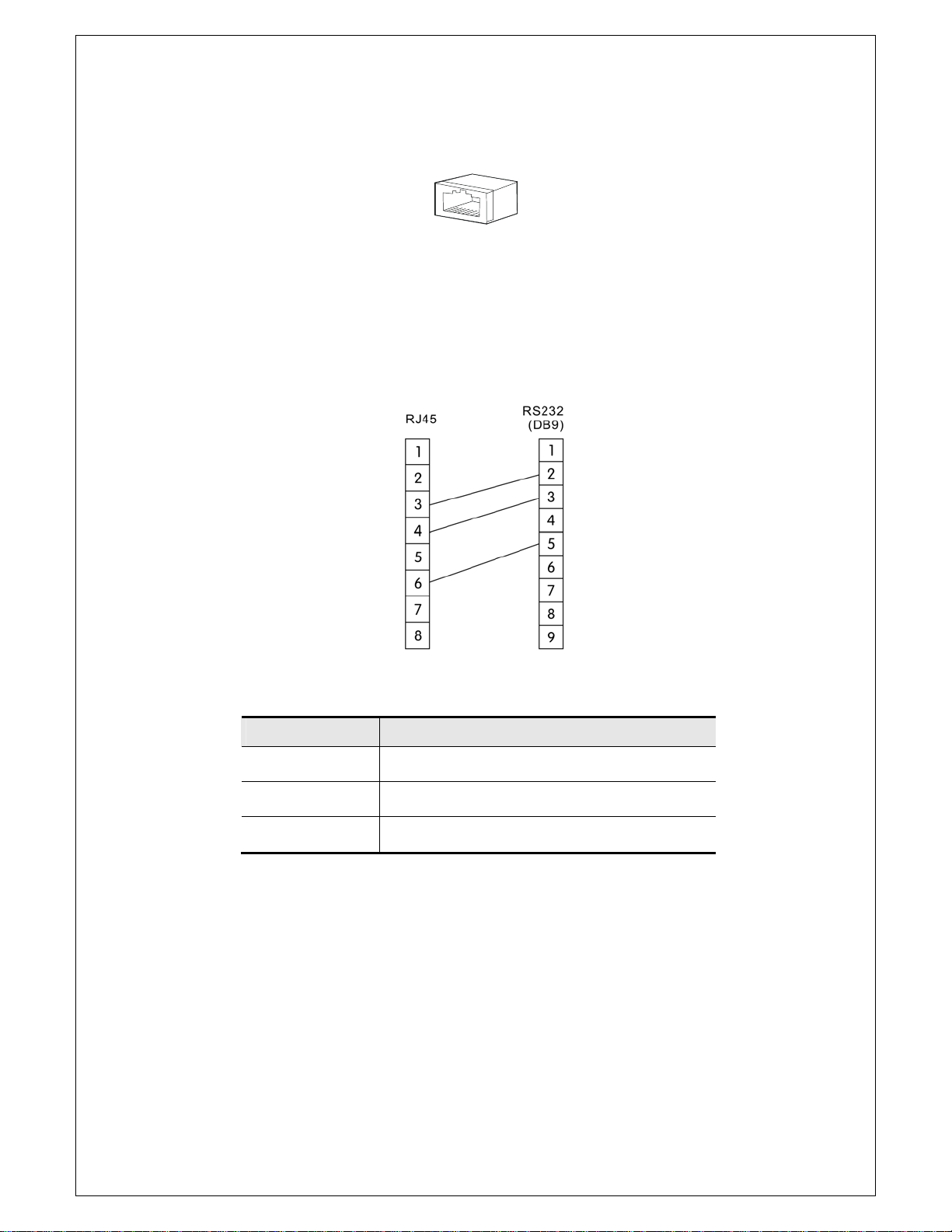
4.2.2 Pin Assignment
Figure 4-2.2 DB9/RS-232 pin assignment
Pin Distribution
2 RXD: accepting of data
3 TXD: transmitter data
5 SG: signal
4.3 Power Connection
4.3.1 Connection Description
The power module provides stable operating power for the system. The input voltage
is 90-265V
or optional -30 VDC to -72VDC. The Power module provides output
AC
various DC voltages to meet the power all the components in the system.
Table 4-3 RS-232 Pin information
025-000634X1 Page 8 of 11
Page 11
5.0 FAULTS
The OTEB-CL-B series EDFA monitors system operation and offers warning of potential problems.
It can correct the majority of problems of the equipment, such as: Equipment tolerance, laser
aging, and changing temperature. The PUMP laser will usually go on working when an alarm is
present. The alarm will disappear if the system parameter recovers into normal range. Some
serious warnings can be eliminated by restarting the power supply of the equipment.
Most warnings will be sent out when the a system parameter is close to or exceeds the permitted
range. In most cases, users cannot modify these status conditions. Status condition limits
require special programming equipment, so the modification can only be made in the factory.
5.1 Warning Status
When the pump laser is in warning status, the status LED will turn red and note of the
status will be briefly displayed on the screen. The warning will not necessarily make the
EDFA stop running. If the warning is removed, it shows that the offending parameter has
returned into normal limits. The screen & LCD will return to their normal status and there
is no need for intervention. However, the problem that caused the alarm should not be
ignored, because there may be some serious system faults.
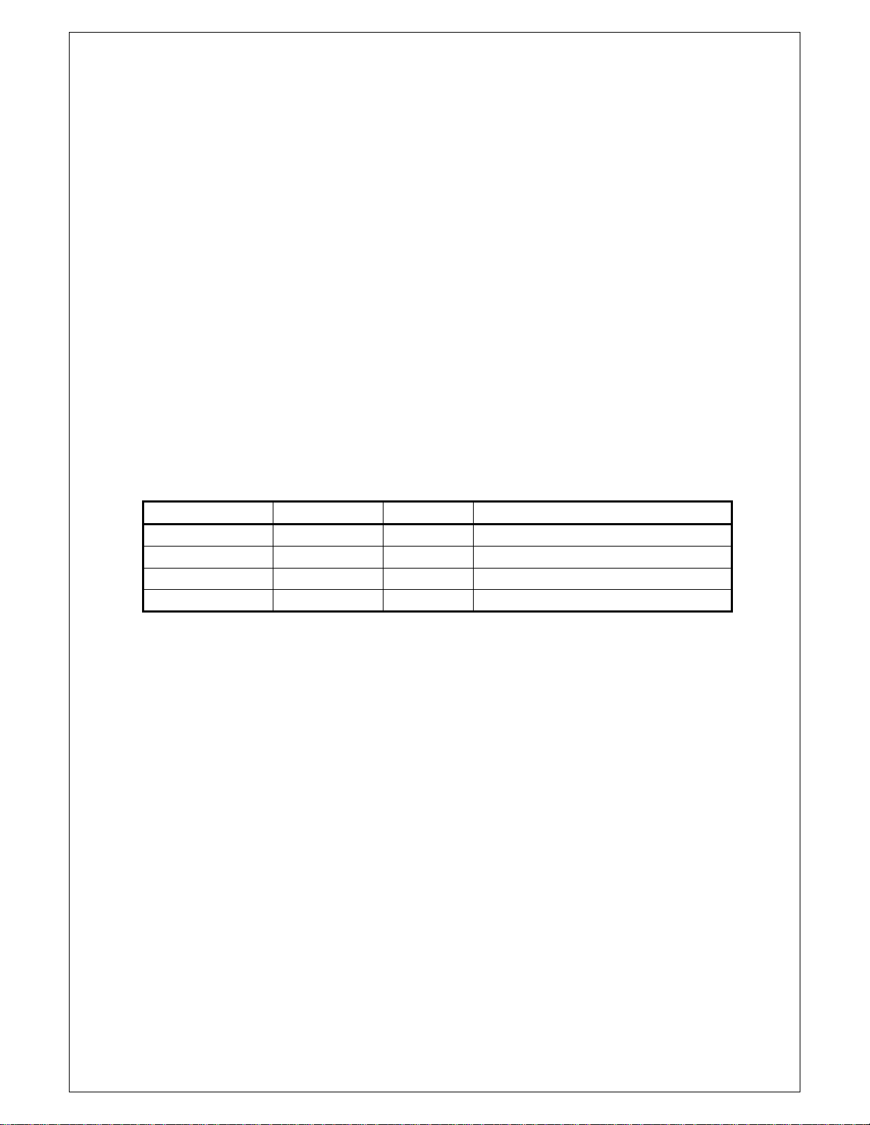
Unit status Status display LED color Explanation
Laser is off Key Off Red The EDFA isn’t operating. It is shut down.
Case temperature - Red Warning when the temp ≥60°C.
Input Input Low Red Optical output power is low.
Output Output Low Red Optical output power is low.
Table 5-1 Warning Status
5.2 Alarm Status
When the pump laser sends out a warning, it may stop working to prevent damage. The
alarm is because some parameter has exceeded its safe working limits or some situation
that may cause damage to the laser. The alarm can usually be eliminated by restarting the
power supply or resetting the key switch. If the user cannot eliminate the alarm, please
contact Olson Technology, Inc.
025-000634X1 Page 9 of 11
Page 12

5.3 Fault Prevention
Please read the below information to prevent some potential problems.
1. Please place the EDFA in a temperature environment of 0°C to +50°C. We suggest
placing the EDFA in low dust environment.
2. Leave a 1RU (1.75") gap above and below the unit to allow adequate cooling.
3. Ensure the rear panel fan & front panel sockets are clean for air flow to let the rear
panel fans to cool the unit.
4. Check the power supply. Verify that all the connections are sound.
5. Keep the optic fiber connectors and bulkhead connectors clean. Prevent output optic
power decreasing caused by optic leakage.
NOTE: ONCE CONNECTED, THERE IS NO NEED TO ROUTINELY DISCONNECT
THE FIBER OPTIC CONNECTORS TO CLEAN THEM. AS LONG AS THEY ARE
CONTINUOUSLY CONNECTED, NO DIRT WILL GET IN THE CONNECTIONS.
025-000634X1 Page 10 of 11
 Loading...