

Page 1
LaserPlus Model LP-OA EDFA
OPERATING MANUAL
24926 Highway 108
Sierra Village, CA 95346
Phone: (800) 545-1022
Fax: (209 586-1022
025-370571 Rev. X1 E-Mail: [email protected]
04/13/11
Page 2

TABLE OF CONTENTS
SAFETY......................................................................................................................................................................3
Safety Precautions..................................................................................................................................................3
Laser Safety Procedure..........................................................................................................................................3
INTRODUCTION........................................................................................................................................................4
Figure 1 - Block Diagram of LP-OA EDFA....................................................................................................4
GENERAL FEATURES..............................................................................................................................................4
PANEL LAYOUT........................................................................................................................................................4
Figure 2 - EDFA Front Panel Layout.............................................................................................................4
Technical Specifications.........................................................................................................................................5
Notes.......................................................................................................................................................................5
Performance Graphs ..............................................................................................................................................6
Figure 3 - Typical EDFA Gain........................................................................................................................6
Figure 4 - Typical EDFA ASE Spectrum........................................................................................................6
Figure 5 - Typical EDFA Noise Figure...........................................................................................................7
DESCRIPTION OF STATUS ALARM........................................................................................................................7
025-370571 X2 www.olsontech.com
2
Page 3

SAFETY
Safety Precautions
The optical emissions from the units are laser-based and may present eye hazards if improperly used. NEVER USE ANY
KIND OF OPTICAL INSTRUMENT TO VIEW THE OPTICAL OUTPUT OF THE UNIT. Be careful when work-
ing with optical fibers. Fibers can cause painful injury if they penetrate the skin.
Laser Safety Procedure
ALWAYS
read the product data sheet and the laser safety label before powering the product. Note the operation wave-
length, optical output power and safety classifi cat i ons.
If safety goggles or other eye protection are used, be certain that the protection is effective at the wavelength emitted by
the device under test BEFORE
ALWAYS
connect a fiber to the output of the device BEFORE power is applied. Power should never be applied without
applying power.
an attached fiber. If the device has a connector output, a connector should be attached that is connected to a fiber. This
will ensure that all light is confined within the fiber waveguide, virtually eliminating all potential hazard.
NEVER
look at the end of the fiber to see if light is coming out. NEVER! Most fiber optic laser wavelengths (1310nm
and1550nm) are totally invisible to the unaided eye and will cause permanent damage. Shorter wavelengths lasers (e.g.,
780nm) are visible and are very damaging. Always use instruments, such as an optical power meter, to verify light output.
NEVER, NEVER, NEVER
includes microscopes, eye loupes and magnifying glasses. This WILL
look into the end of a fiber on a powered device with ANY sort of magnifying device. This
cause a permanent and irreversible burn on your
retina. Always double check that power is disconnected before using such devices. If possible, completely disconnect the
unit from any power source.
If you have questions about laser safety procedures, please call Olson Technology before powering your product.
025-370571 X2 www.olsontech.com
3
Page 4
INTRODUCTION
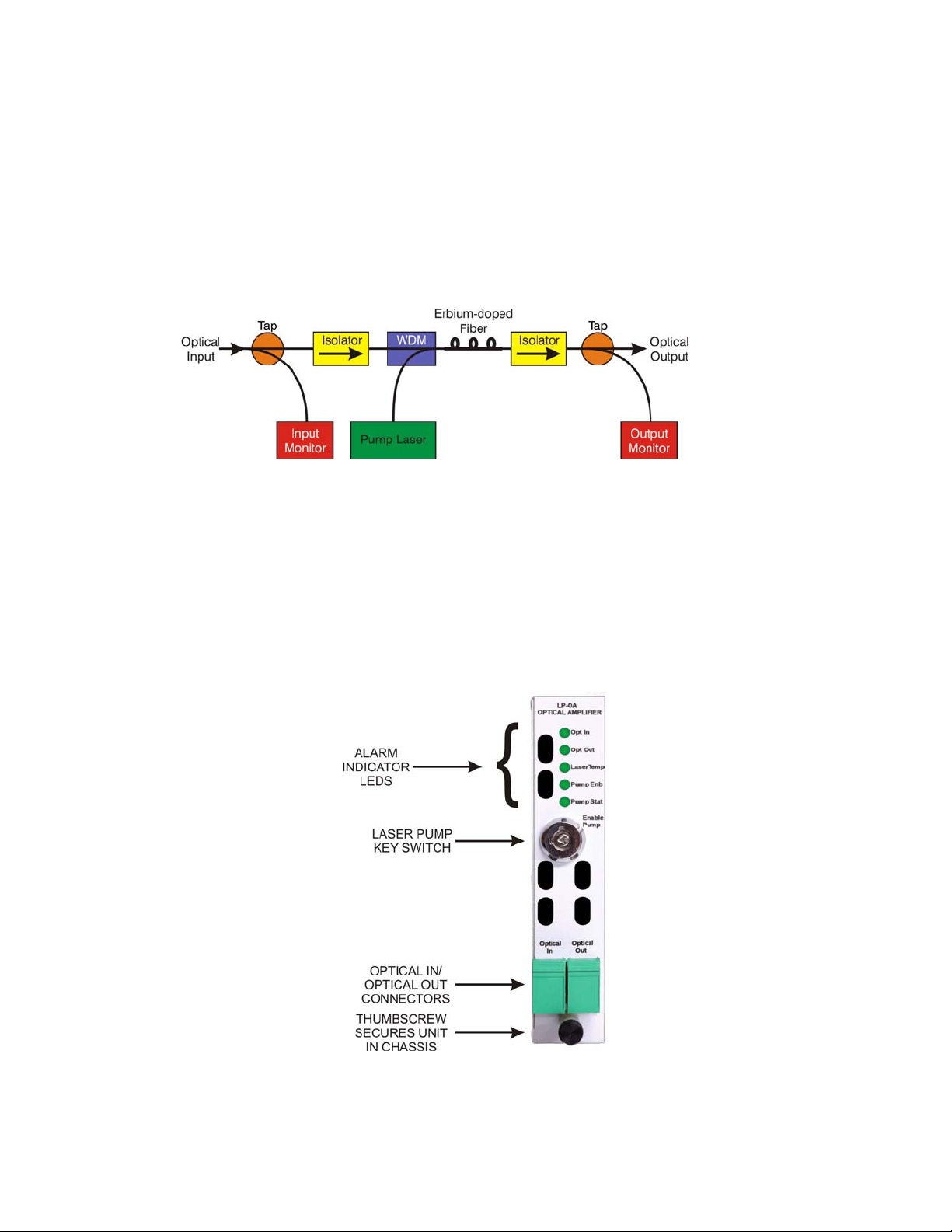
The Olson Technology, Inc. LaserPlus Model LP-OA Erbium Doped Fiber Amplifier (EDFA) is a cost-effective, full
featured Optical Amplifier compatible with the LaserPlus product line manufactured by Olson Technology, Inc. Designed for optical amplification of CATV or L-Band signals, the LP-OA EDFA is ideal for CATV Hybrid Fiber Coax
(HFC) applications and Fiber-to-the-Premise (FTTP) deployments using Active/Passive Optical Network (AON/PON)
architectures. The LP-OA offers simple plug and play operation,
The Model LP-OA EDFA utilizes a high-quality, EDFA gain module that provides optical output powers ranging from
+13dBm to +18dBm at the rated optical input power of +3dBm over a wavelength range from 1540nm to 1560nm. The
EDFA has low electrical power dissipation. That maximizes reliability by minimizing self-heating.
Figure 1 — Block Diagram of LP-OA EDFA
GENERAL FEATURES
The LP-OA includes five front panel indicators for Optical Input Power, Optical Output Power, Laser Temperature,
Pump Enable and Pump Status that allow the health of the unit to be assessed at a glance. The unit also provides extensive SNMP capability that includes the ability to read the follow ing parameters; Optical Input Power, Optical Output
Power, Module Temperature, Pump Laser Current, Pump Laser Power, Pump Laser Temperature and alarms for High
Current, High Temperature, Temperature Stable and Laser Enable.
PANEL LAYOUT
Figure 2 — EDFA Front Panel Layout
025-370571 X2 www.olsontech.com
4
Page 5

Technical Specifications
Minimum Typical Maximum Units
Optical Specifications
Optical Output Power1
Optical Input Range2
Gain with -30dBm Opt. In
Gain with +3dBm Opt. In
Noise Figure
Pump Power Leakage
Optical Return Loss
Optical Connector
Electrical Specifications
Power Supply Voltage
Power Supply Current
Power Consumption
Environmental Specifications
Operating Temperature
Storage Temperature
Humidity3
Physical Characteristics
Weight
Dimensions (W x D x H)
+13 +22 dBm
-6 +4 dBm
31 dB
13 dB
5 6.5 dB
-30 dB
45 dB
SC/APC
+5 V
DC
600 mA
3 W
0 +50 °C
-10 +60 °C
5 95 %
1 lb.
2.2 kg
4.5 H x 0.96W x 8.75D in.
114 H x 24.4W x 222 D mm
Notes
1. Optical power output options are as follows:
Part Number Optical Output Power
LP-OA-13-SA
LP-OA-14-SA
LP-OA-15-SA
LP-OA-16-SA
LP-OA-17-SA
LP-OA-18-SA
LP-OA-19-SA
LP-OA-20-SA
LP-OA-21-SA
LP-OA-22-SA
+13dBm
+14dBm
+15dBm
+16dBm
+17dBm
+18dBm
+19dBm
+20dBm
+21dBm
+22dBm
2. Recommended input power range. Lower optical powers will give a red light.
3. Humidity is RH non-condensing.
025-370571 X2 www.olsontech.com
5
Page 6
Performance Graphs
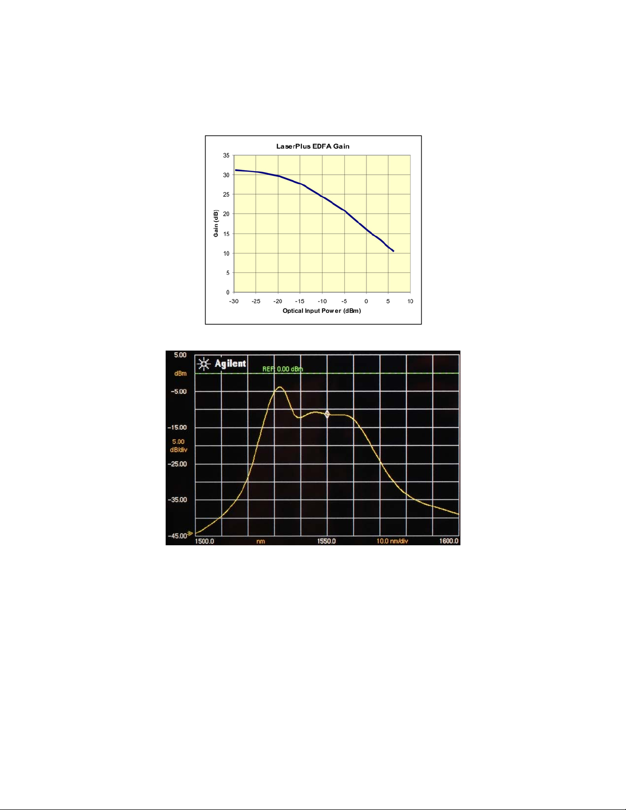
Figure 3 shows the typical gain of the LP-OA EDFA. It is easiest to understand the operation of an EDFA once you realize
that they are saturated output power devices. In other words, they tend to put out full power regardless of what the input
conditions are. This makes the gain of the EDFA’s versus the optical input power look very odd. Figure 3 shows the typical
behavior of a +17dBm optical output power EDFA. Figure 3 suggests that the gain of the EDFA drops as the optical input
power is increased. In fact, for optical inputs above about -10dBm, the optical output power is a constant +17dBm.
Figure 3 — Typical EDFA Gain
Figure 4 — Typical EDFA ASE Spectrum
025-370571 X2 www.olsontech.com
6
Page 7
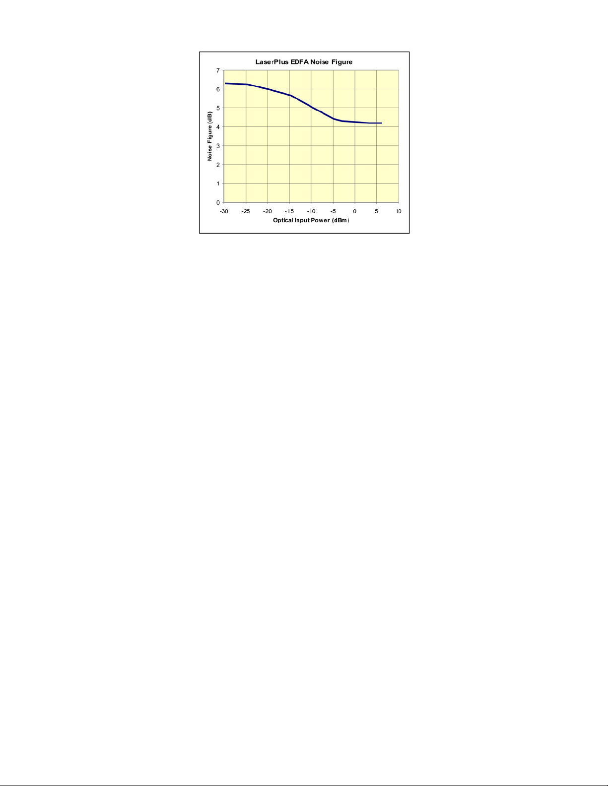
Figure 5 — Typical EDFA Noise Figure
DESCRIPTION OF STATUS ALARM
The front panel indicator LED indicator may be red, green, or off. When the LED is green the EDFA is operating properly.
When the LED is off, the unit is off. A red LED indicates an alarm condition. The LP-OA includes five front panel indicators for Optical Input Power, Optical Output Power, Laser Temperature, Pump Enable and Pump Status that allow the
health of the unit to be assessed at a glance. The unit also provides extens ive SNMP capability that inclu des the ability to
read the following parameters; Optical Input Power, Optical Output Power, Module Temperature, Pump Laser Current,
Pump Laser Power, Pump Laser Temperature and alarms for High Current, High Temperature, Temperature Stable and
Laser Enable.
025-370571 X2 www.olsontech.com
7
 Loading...