

Page 1
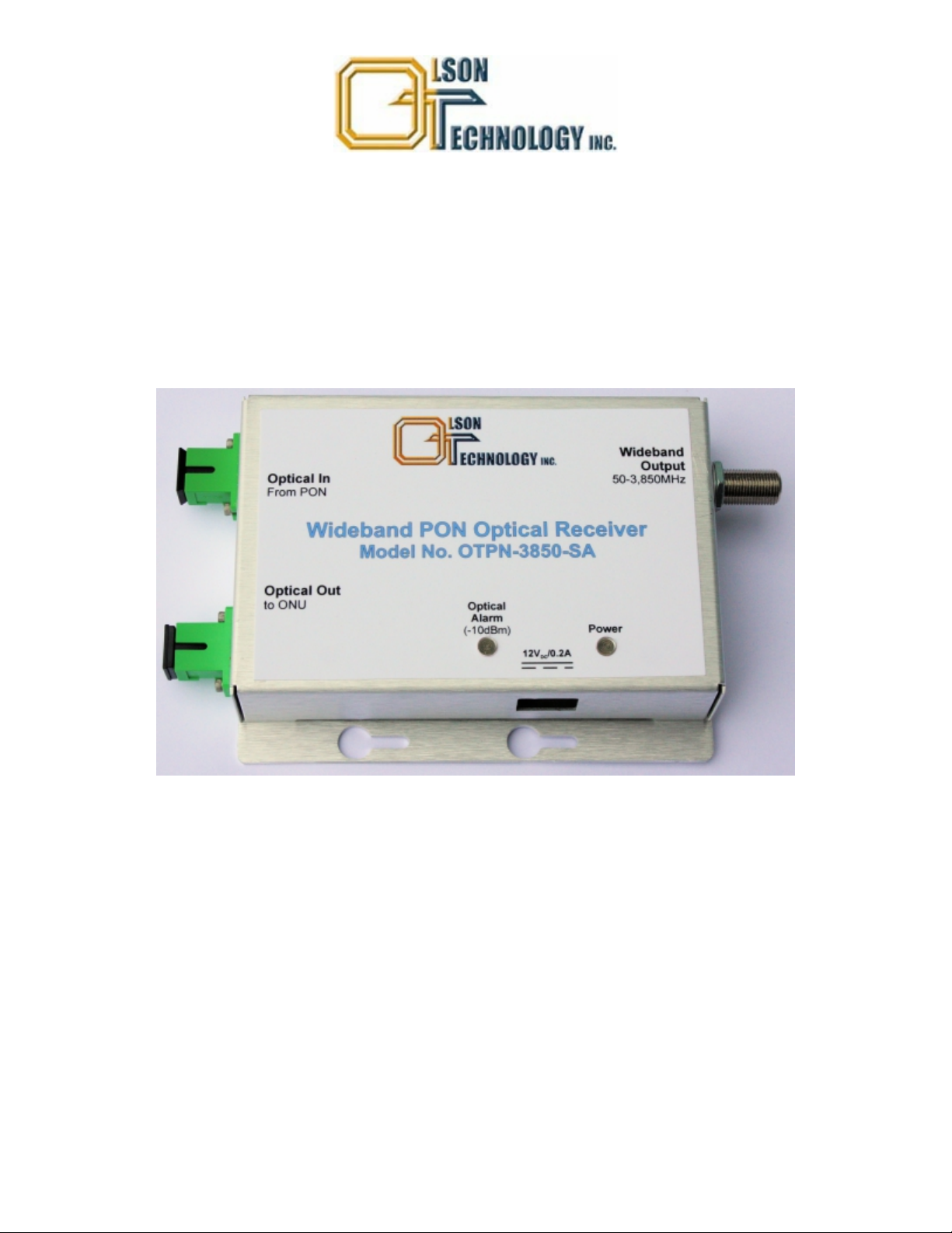
Table of Contents
Model OTPN-3850-SA
3.85GHz Wideband FTTH PON Receiver
Instruction Manual
Phone: (209) 586-1022
(800) 545-1022
FAX: (209) 586-1026
E-Mail:[email protected]
025-000641 REV X5 06 Sep 2012 Page 1
Page 2

Table of Contents
INTRODUCTION
THEORY OF OPERATION
BLOCK DIAGRAM
INSTALLATION / ENVIRONMENTAL CONSIDERATIONS
OPTICAL CONNECTORS AND CLEANING
INTERNAL CONTROLS
EXTERNAL INDICATORS AND CONNECTORS
SETUP AND OPERATION
ACCESSORIES AND SYSTEM APPLICATIONS
. . . . . . . . . . . . . . . . . . . . . . . . . . . . . . . . . . . . . . . . . . . . . . . . . . . . . . . . . .
. . . . . . . . . . . . . . . . . . . . . . . . . . . . . . . . . . . . . . . . . . . . . . . . . .
. . . . . . . . . . . . . . . . . . . . . . . . . . . . . . . . . . . . . . . . . . . . . . . . . . . . . . . .
. . . . . . . . . . . . . . . . . . . . . . . . . . . . . . . . . . .
. . . . . . . . . . . . . . . . . . . . . . . . . . . . . . . . . . . . . . . . . . . . . . . . . . . .
. . . . . . . . . . . . . . . . . . . . . . . . . . . . . . . .
. . . . . . . . . . . . . . . . . . . . . . . . . . . . . . . . . . . . . . . . . . . . . . . . . . . .
. . . . . . . . . . . . . . . . . . . . . . . . . . . . . . . .
. . . . . . . . . . . . . . . . . . . . . .
3
3
4
5
6
6
6
7
8
025-000641 REV X5 Olson Technology, Inc. Page 2
Page 3

INTRODUCTION
The Olson Technology, Inc. Model OTPN-3850-SA provides 50-3,850MHz bandwidth,
allowing it to carry CATV signals from 50-870MHz along with two stacked 950-2,150MHz
groups of L-Band signals. The L-Band signals are at a level at least 10dB below the CATV
signals.
The optical input contains downstream forward path CATV and L-Band signals at 1550nm,
downstream Ethernet data at 1490nm and upstream Ethernet data at 1310nm. The optical
output passes the 1310nm and 1490 signals. The 1550nm wavelength goes to a photodiode
and is amplified. The optical input level is sensed to trigger an optical alarm when the input
light level is less than -10dBm. The input optical level is also used to control a PIN diode
attenuator to maintain constant RF level as the optical input level varies from 0dBm to -6dBm.
The signal is then amplified and output to a single “F” connector output.
The OTPN-3850-SA Integrated PON Receiver dimensions are 1.05" H x 3.15" W x 4.75" L.
Optical connections are via two SC/APC connectors, one for the optical input carrying
1310nm, 1490nm & 1550nm, the second for the optical output carrying the 1310nm and
1490nm optical signals. The unit is powered from +12 to +16 Volts DC at 0.2A maximum. A
Green Power LED is lit whenever valid supply voltage is applied. A Red LED is lit only when the
1550nm optical power drops below -10dBm, the minimum usable optical input level. The right
side of the unit has a single “F” connector providing a 50-3,850MHz signal.
The OTPN-3850 is designed to give optimum performance at a received CATV optical power
(1550nm) of -4dBm although it will give good performance over the full rated optical input
range of 0dBm to -6dBm.
THEORY OF OPERATION
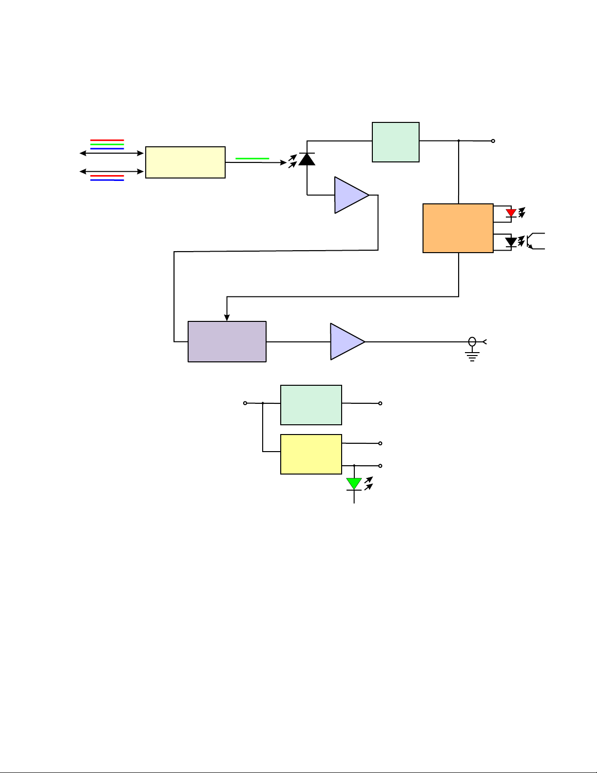
Refer to the Block Diagram for the following discussion. The Optical In to the receiver, actually
carries three wavelengths. The 1550nm ±10nm wavelength carries the downstream CATV
and L-Band signals. This wavelength passes through the FWDM (Filter Wavelength Division
Multiplexer) to the optical detector. The 1310nm and 1490nm wavelengths usually carry the
Ethernet signals in a Fiber-to-the-Home (FTTH) PON application. They pass through the
FWDM to the Optical Out port. The 1490nm wavelength usually carries the downstream
Ethernet signals and the 1310nm wavelength carries the upstream Ethernet signals.
The 1550nm light that reaches the photodiode (PD) is processed by two different circuits. The
first circuit measures the DC average current to determine what optical light level is hitting the
photodiode. This is converted to a logarithmic value with a scale factor of 1 Volt per decade. An
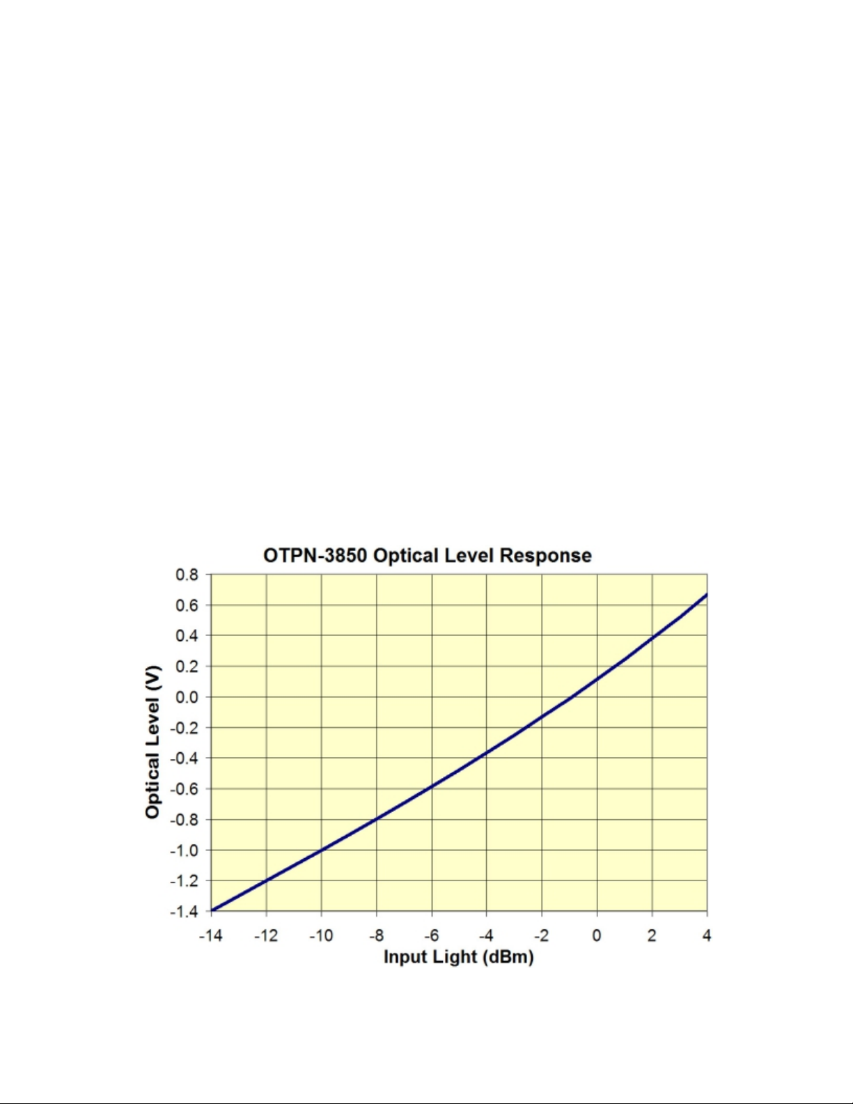
input level of -10dBm yields -1.0 Volts, 20dBm yields -2.0 Volts, etc. See Figure 3 for details of
this output. The photodiode RF output also goes to a low-noise, wide-bandwidth RF amplifier.
The output of the first amplifier goes to a wide bandwidth PIN diode attenuator which is controlled by the Optical Level signal to keep the RF output constant. For each 1dB drop in the
input optical level, the RF attenuation of the PIN diode attenuator is decreased by 2dB, matching the optical-to-RF conversion characteristics of the optical detector. This circuit is optimized
to operate over the optical input range from -6dBm to 0dBm. Note that these power levels
ONLY refer to the 1550nm energy in the fiber. Since there are multiple wavelengths
on the fiber, a simple optical power meter may be fooled by the 1310nm or 1490nm
power that may also be contained in the fiber. The easiest way to measure only the
1550nm power is to use the optical level function that is built into the OTPN-3850. See Figure
3 for the exact transfer function. The optical level function is calibrated at the factory and
rivals the accuracy of most field optical power meters.
025-000641 REV X5 Page 3Olson Technology, Inc.
Page 4
BLOCK DIAGRAM
Olson Technology OTPN-3850-SA
3.85GHz Wideband FTTH PON Receiver
1310, 1490, 1550nm
Optical In
Optical Out
1310 & 1490nm
FWDM
+12 to +16
1550nm
50-3,850 MHZ
PIN Diode
A ttenuator
Volts DC
Photodiode
Amplifier
Attenuator Control Voltage
Amplifier
Filtering
Optical
Level
Detect
+12 to +16V
Light Level
Control
Circuitry
Optical Level
Optical
Alarm
(-10dBm)
RF Output
50-3,850 MHz
“F” Connector
C
E
Alarm
Out
DC-DC
Converter
+5V Output
-5V
+5V
Power
Notes:
1) Bandwidth = 50MHz to 3,850MHz
2) Flatness 50-870MHz = ±1.5dB
950-3,850MHz = ±2.5dB
Any 20MHz = ±0.5dB
3) CATV Output Level is +23dBmV/Ch Typical at 3% OMI/Ch
4) L-Band Output Level is +13dBmV/Ch or Less (L-Band signals
require much lower CNR than CATV signals, thus can operate
at lower RF levels.)
5) AGC Range ±2dB for Opt. In from 0 dBm to -6dBm
6) At -4dBm Optical Input, Min. CATV performance is;
CNR = 47dB CSO = -55dBc CTB = -55dBc
7) Loss of Light Threshold = -10dBm ±1dB (1550nm power only)
025-000641 REV X5 Page 4Olson Technology, Inc.
Page 5
INSTALLATION / ENVIRONMENTAL CONSIDERATIONS
The OTPN-3850 receiver is specified to operate from -40°C to +65°C. It usually does not
require an air-conditioned environment. It should be mounted in an adequately-ventilated
area. Like all electronic equipment, it will generally have a longer life span if it is not operated
at the extremes of the temperature range. Installation in wet areas or areas of extremely high
humidity should be avoided. Extremely dirty or dusty areas should also be avoided if possible.
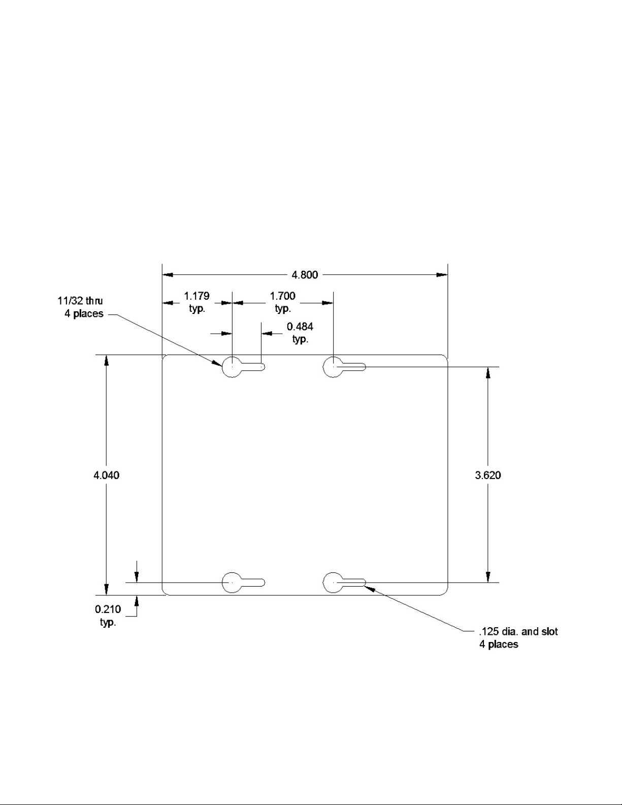
The OTPN-3850 may be installed and operated in any position on a flat surface. The unit has
four slots in the bottom plate to accommodate mounting hardware. If mounting requires a
wood screw, use #4 pan-head sheet metal screws. These are commonly available at hardware
stores. If mounting with a machine screw (to tapped holes), use 4-40 pan-head screws.
Figure 1 shows the dimensions of the bottom plate of the OTPN-3850.
FIGURE 1 - OTPN-3850 MOUNTING PLATE
025-000641 REV X5 Page 5Olson Technology, Inc.
Page 6
OPTICAL CONNECTORS AND CLEANING
The standard optical connectors on the OTPN-3850 are SC/APC angle-
GREEN
polished connectors. The internal fiber ends can be damaged by the insertion of contaminated connectors. Some types of customer damage to the connectors are not
covered under the warranty. Fiber connectors should never be left uncovered.
Prepackaged alcohol wipes are the most convenient means of cleaning optical connectors. Clean alcohol and lint free wipes or swabs may also be used.
INTERNAL CONTROLS
There are no internal user adjustments. There is no reason to open the unit. Any
attempt to do so will void the manufacturer’s warranty.
EXTERNAL INDICATORS AND CONNECTORS
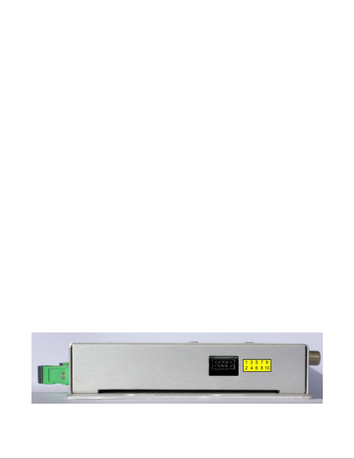
There are two external indicator lights and a 10-pin electrical connector. One of the indicators
lights green to indicate that power has been applied to the unit. The second red indicator only
lights red when the 1550nm optical input power drops below -10dBm.
The 10-pin connector mates to the following connector;
OTPN-3850 Connector: Molex Part Number: 87833-1020
Mating Connector: Molex Part Number: 51110-1051
Terminals: Molex Part Number: 50394-8100
The function of the ten (10) pins is shown below;
Pin 1 Alarm Collector (Optically isolated NPN transistor) (Yellow on OTPS-12A-10M)
Pin 2 Alarm Emitter (Optically isolated NPN transistor) (Blue on OTPS-12A-10M)
Pin 3 Input Power, +12 to +16 Volts DC (Red on OTPS-12A-10M)
Pin 4 Ground (Black on OTPS-12A-10M)
Pin 5 Optical Monitor (Through 1K resistor. See Figure 3.) (White on OTPS-12A-10M)
Pin 6 +5 Volts (Through 200 Ohm resistor) (Orange on OTPS-12A-10M)
Pin 7 (No wire on OTPS-12A-10M)
Pin 8 Ground (Black on OTPS-12A-10M)
Pin 9 (No wire on OTPS-12A-10M)
Pin 10 (No wire on OTPS-12A-10M)
Olson OTPS-12A-10M (Sold separately) is recommended for use with the OTPN-3850.
FIGURE 2 - Electrical Connector Pin Configuration
025-000641 REV X5 Page 6Olson Technology, Inc.
Page 7
SETUP and OPERATION
Setting up the two transmitters shown in Figure 4 is key to successful operation. We recommend the following steps. 1) Adjust the RF drive level into the CATV transmitter to yield 3%
OMI per channel. Measure it’s optical output power. 2) The optical output of the L-Band transmitter should be set about 5dB below the optical output power of the CATV transmitter. This
may require an optical attenuator.
Mount the OTPN-3850 and apply power. Connect the incoming fiber (
1550nm CATV signal from the headend to the residence) to the port. Connect the
upstream fiber (the fiber that carries the 1310nm & 1490nm Ethernet signals from the resi-
dence to the headend) to the Optical Out port. Connect the Wideband Output “F” connector to
the equipment that processes the CATV and L-Band signals. Often this may be an L-Band
DeStacker. The OTPN-3850 is designed for optimum performance at an optical input of -4dBm
(1550nm power only). The easiest way to verify the 1550nm input power is to measure the
voltage on pin 5 of the electrical connector (See Figure 2 to locate pin 5). The voltage that is
measured on pin 5 can be interpreted in Figure 3. An optical input of -4dBm will yield a voltage
of about -0.365 Volts on pin 5. The OTPN-3850 will give acceptable CATV performance for a
1550nm optical input ranging from 0dBm to -6dBm. This corresponds to voltages on pin 5
from +0.115 Volts (0dBm) to -0.585 Volts (-6dBm). This is the preferred method to verify the
1550nm power. An optical power meter can be fooled if there is 1490nm or 1310nm energy on
the fiber as well. The Optical Alarm LED should be dark and the Power LED should be lit green.
The system should now be functional.
Now verify the CATV RF Levels. They should be about +23dBmV per analog CATV channel.
Now return to the L-Band transmitter and adjust the RF drive level so that the L-Band channels
are about +13dBmV or less.
the fiber that carries the
Optical In
FIGURE 3 - Optical Monitor Output Voltage vs. Input Light Level
025-000641 REV X5 Page 7Olson Technology, Inc.
Page 8
ACCESSORIES AND SYSTEM APPLICATIONS
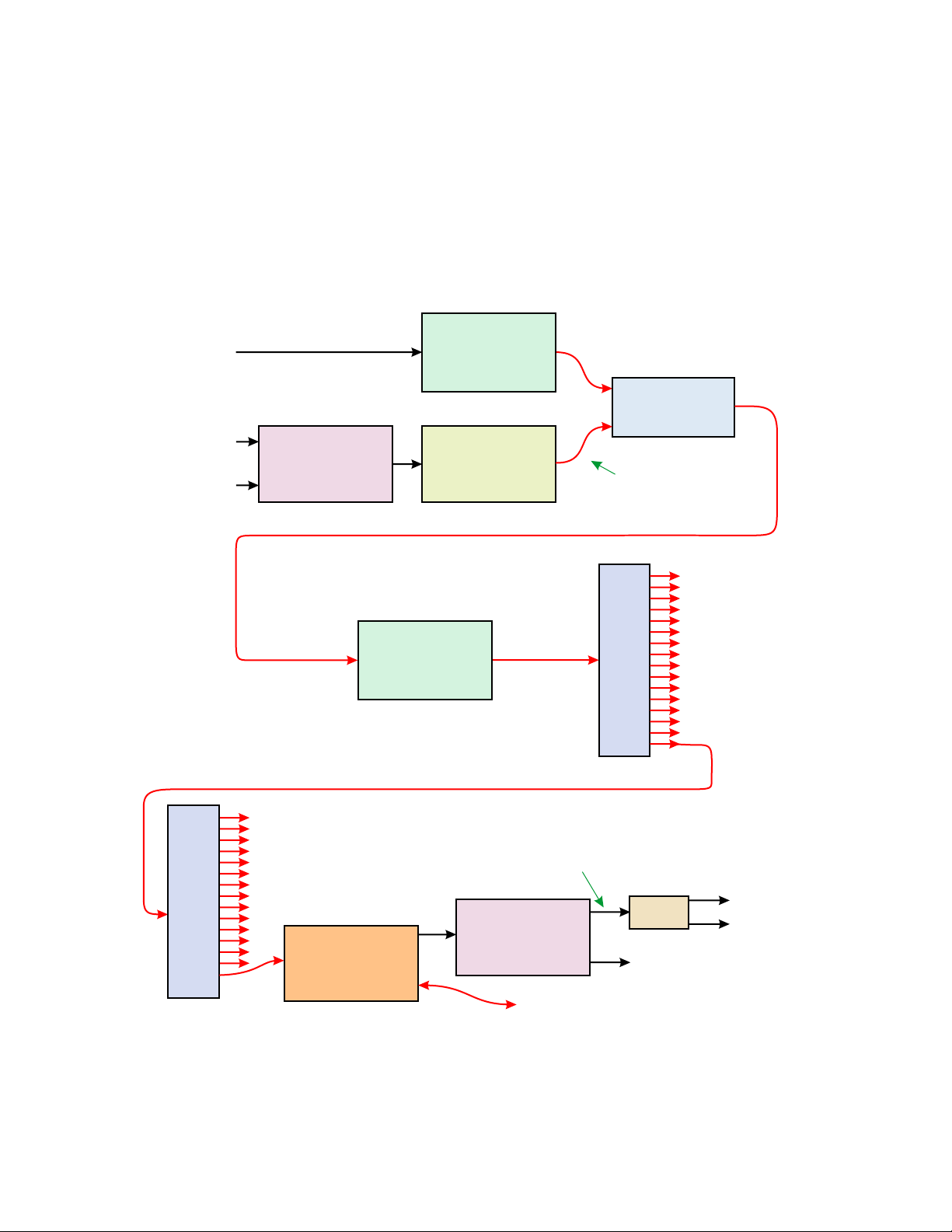
The OTPN-3850 makes up half of a typical FTTH PON system. The other half is the transmit
hardware. Figure 4 shows a typical configuration of a complete FTTH PON system. The two LBand signals are first stacked and then converted to light separately from the CATV signals.
The optical outputs of the CATV and L-Band transmitters are combined by a DWDM Mux and
then amplified by an EDFA. The EDFA output is then split a large number of times and a portion
of that signal input to numerous OTPN-3850’s. The two optical signals from the two
transmitters are added together at the photodiode and decoded as a single 50-3,850MHz RF
signal. The L-Band DeStacker then separates the two original 950-2,150MHz L-Band signals.
Typically the CATV signal is on the same DeStacker output as the L-Band 1 signal.
CATV Tx
CATV Signals
50-870MHz
L-Band 1
950-2,150MHz
L-Band 2
950-2,150MHz
RF
L-Band Stacker
e.g. Global
e.g. OTOT-1000-FF
OTOT-1000-HH
(DWDM Ch 34)
RF
L-Band Tx
e.g. OLAT-X4038
(DWDM Ch 38)
or
Optical
2-Channel
DWDM Mux
e.g. OT-DWDM-2
Optical output power is
typically at least 5dB below
Optical
the CATV transmitter optical
output power. This may
require an attenuator
Optical Splitter
e.g. OTCP-1x16
Optical
OTPN-3850
Receiver
EDFA
e.g. OTEB-CO
or
OTEA-CM
RF
Optical
Optical
Optical
CATV+L-Band 1
50-2,150MHz
L-Band DeStacker
e.g. Global
Ethernet Equipment
Optical Splitter
e.g. OTCP-1x16
Diplex
Filter
L-Band 2
950-2,150MHz
CATV
L-Band 1
950-2,150MHz
Note: For simplicity, the hardware associated with the Ethernet Signals
usually associated with this type of system are not fully shown.
FIGURE 4 - Typical System Application Using the OTPN-3850
025-000641 REV X5 Page 8Olson Technology, Inc.
 Loading...