

Page 1

OTM-3000-HR
FREQUENCY AGILE - HIGH RESOLUTION
TELEVISION MODULATOR
INSTRUCTION MANUAL
Phone:
E-Mail: [email protected]
025-000258 REV B 8/23/01
(209) 586-1022
(800) 545-1022
Fax:
(209) 586-1026
www.olsontech.com
Page 2

1) INTRODUCTION
The OTM-3000 HR is a frequency agile F .C.C. compatible television modulator that provides the ability of
channel selection from 41.25MHz through 445.25MHz in lMHz increments. All channels are selectable by
front panel DIP switches, including F .C.C. offsets of +12.5KHz and +25KHz.
The OTM-3000 HR high resolution modulator used with companion OTD-2000 HR high resolution demodulator provides video bandwidth to 9.5MHz with carrier spacing as close as 12MHz. No audio capability is
provided.
The OTM-3000 HR offers excellent input sensitivity and high output level, typically +60dBmV . Also, this unit
has very high out-of-band carrier to noise ratio (>80dB) which allows virtually an unlimited number of
modulators to be combined without the need for external bandpass filters. The OTM-3000 HR has low
power consumption (14 watts @ 115 VAC) for reliable long term operation.
OTM-3000-HR
FREQUENCY AGILE - HIGH RESOLUTION
TELEVISION MODULA TOR
2) FREQUENCY SELECTION
Frequency selection is made by properly setting the two 8-position switches to the corresponding code.
Select the desired frequency code from T able #1 or the code card supplied with the unit, then set the DIP
switches from left to right.
The code card list standard TV channels. If these are used, select non-adjacent channels for spacings no
closer than 12MHz.
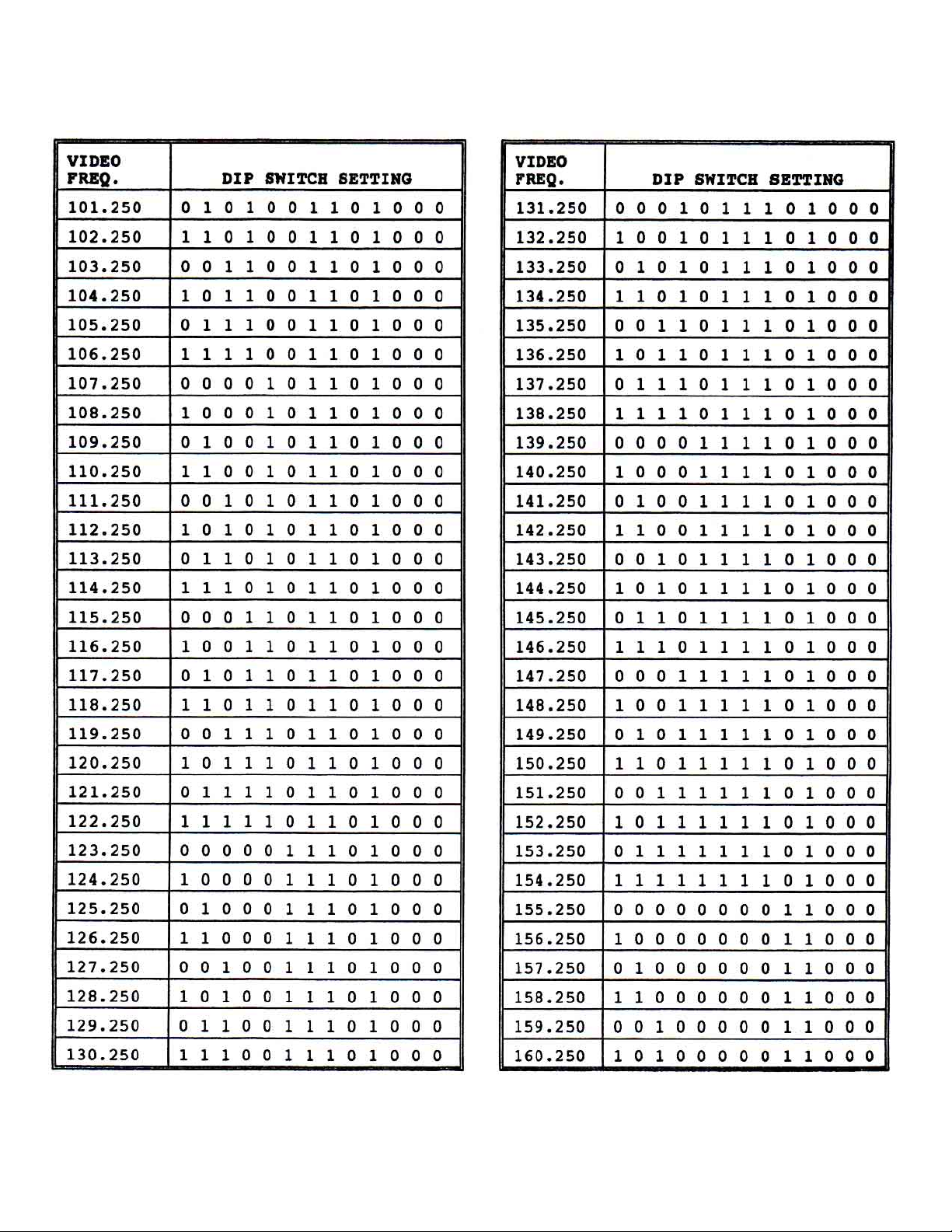
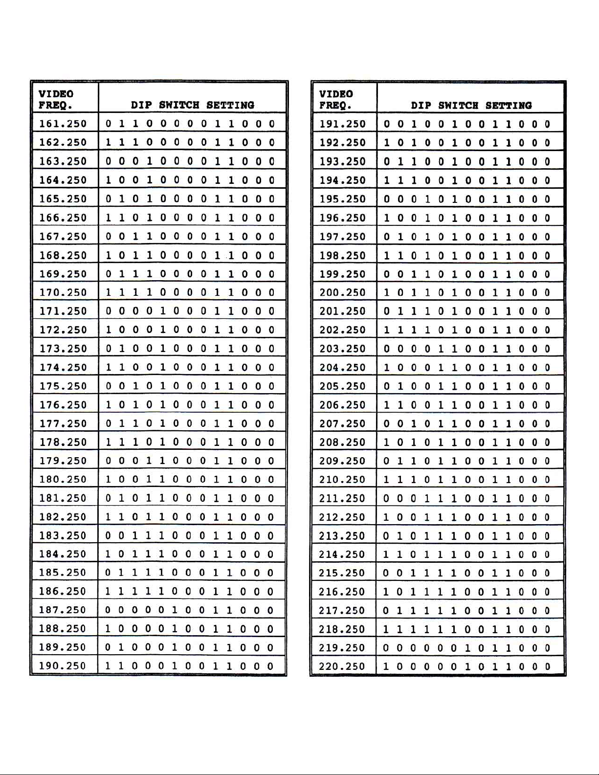
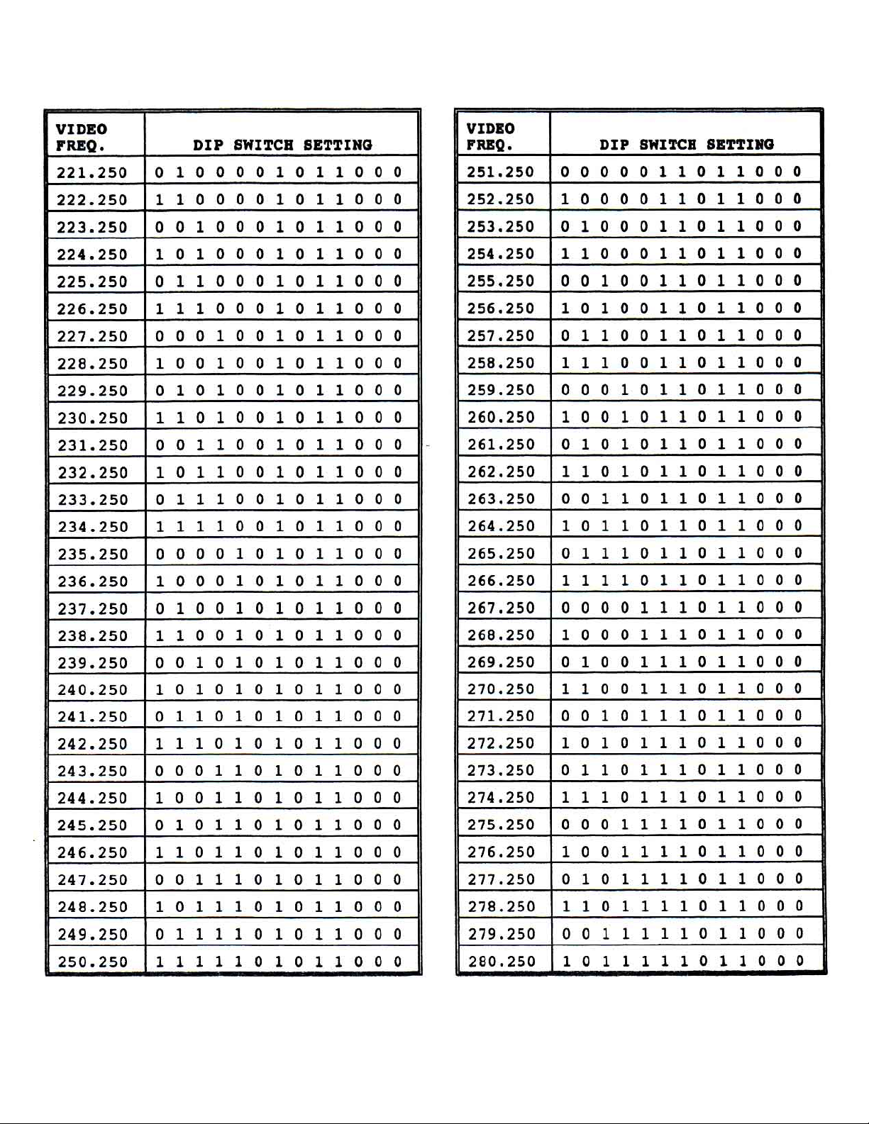
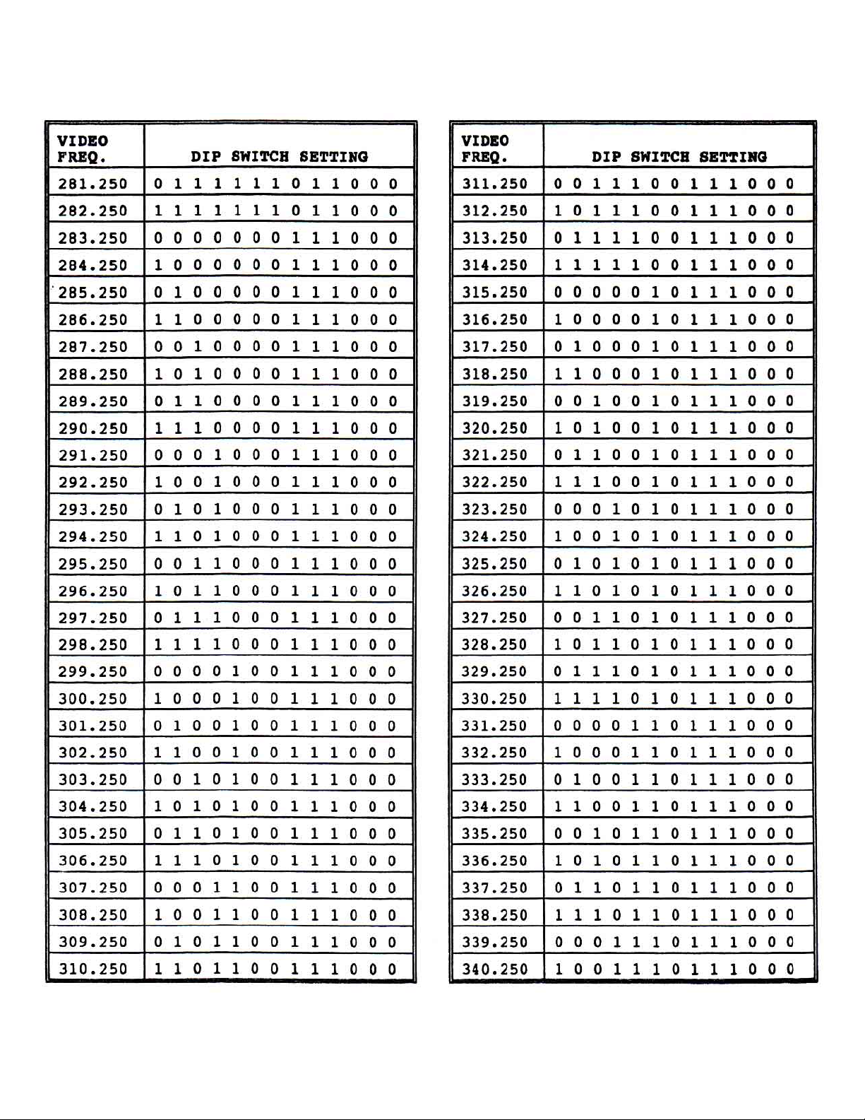
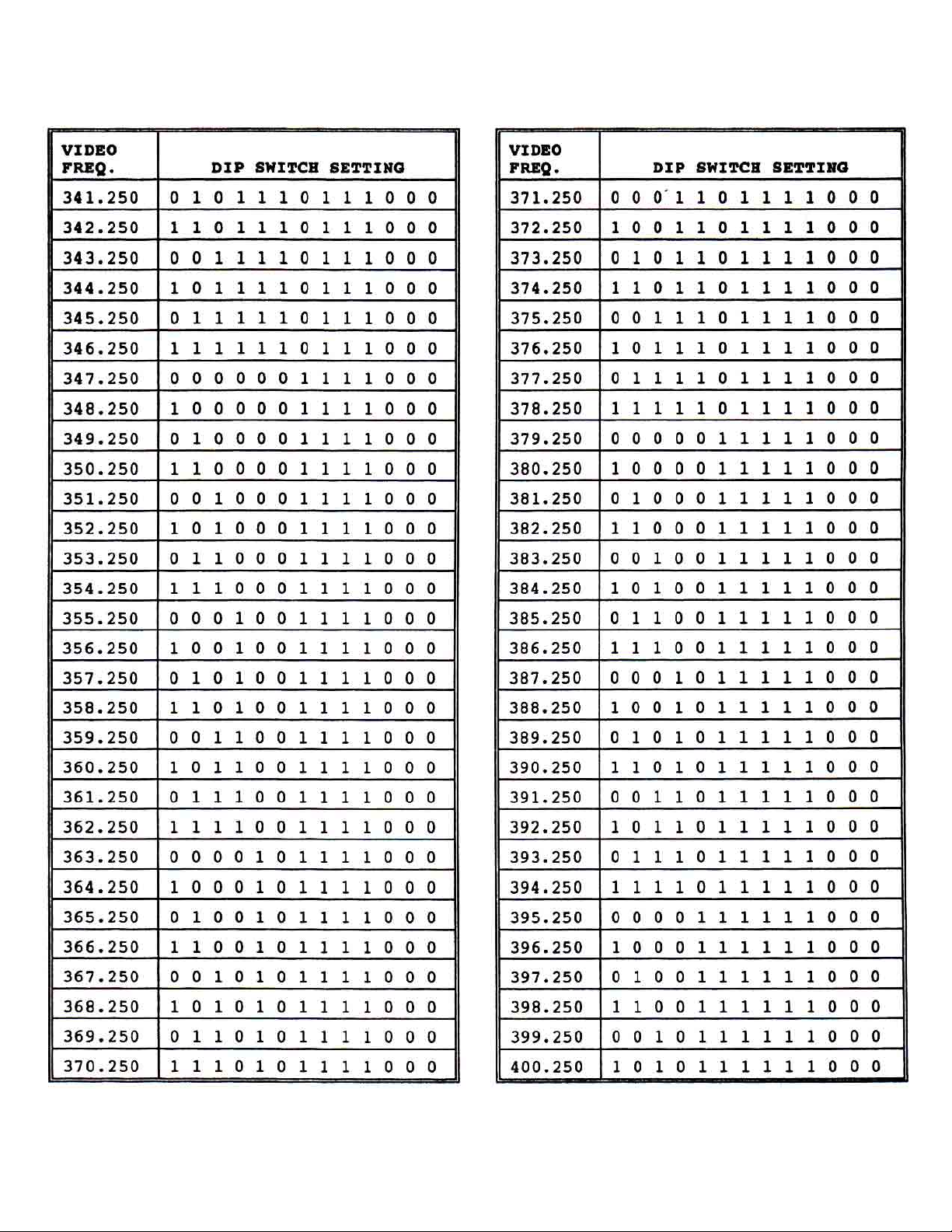
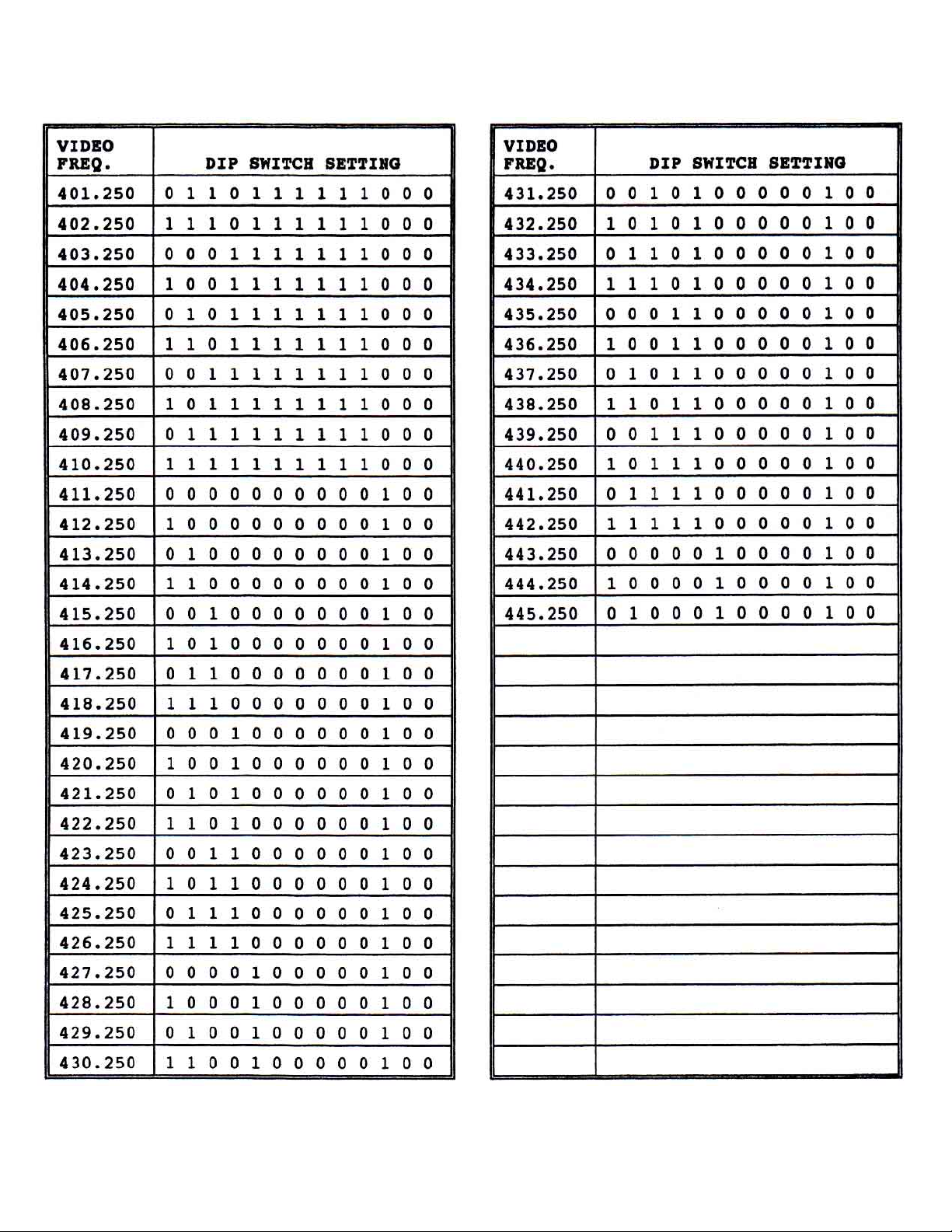
T able #1 is a listing that shows the binary code for all tunable frequencies from 41.25MHz to 445.25MHz in
1MHz steps. Set each DIP switch as indicated.
3) F .C.C. OFFSET SELECTION
Each channel listed on the code card has an “OFFSET CODE” number in either the left or right hand column.
“OFFSET CODE” #1 corresponds to 0KHz offset, Code #2 is 12.5KHz, and Code #3 corresponds to
+25KHz offset.
T o select the desired offset, simply set properly the 4-position DIP switches to the corresponding of fset
code as shown in Figure #1.
025-000258 REV B
Page 2
Page 3
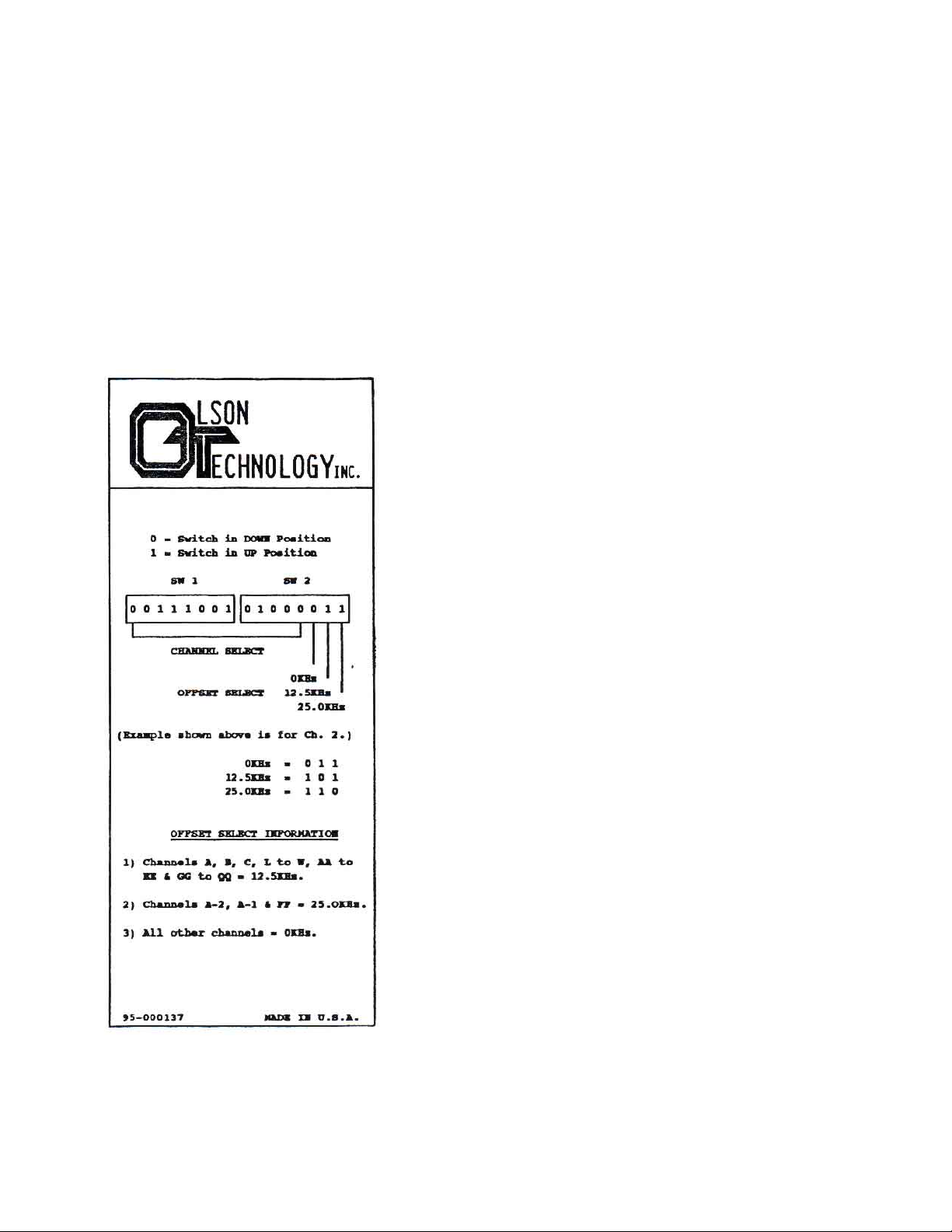
3) F .C.C. OFFSET SELECTION
Each channel listed on the code card has an “OFFSET CODE” number in either the left or right hand column.
“OFFSET CODE” #1 corresponds to 0KHz offset, Code #2 is 12.5KHz, and Code #3 corresponds to
+25KHz offset.
T o select the desired offset, simply set properly the 4-position DIP switches to the corresponding of fset
code as shown in Figure #1.
Figure 1
OFFSET SELECT CHAR T
OTM-3000 HR MODULA T OR
025-000258 REV B
Page 3
Page 4
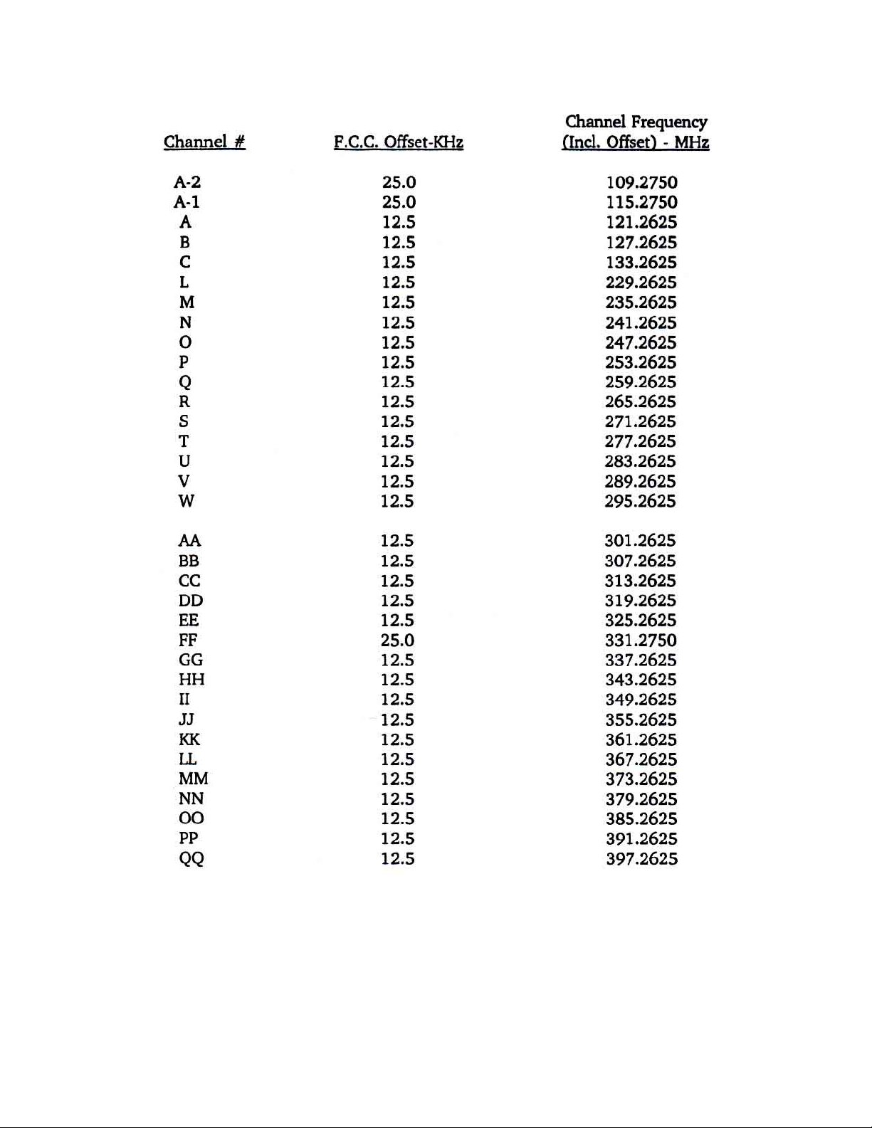
4) F .C.C. OFFSET FREQUENCIES
025-000258 REV B
Page 4
Page 5

5) VIDEO MODULA TION ADJUSTMENT
A) Connect a video source of approximately 1V p-p to the video input connector (75 ohms input Z) on
the rear panel.
B) Rotate the video modulation control slowly clockwise until the video overmodulation light turns on.
The light may blink with differences in average picture level.
high, compression or lack of contrast will occur during high intensity scenes.
6) RF CARRIER LEVEL ADJUSTMENT
Using a field strength meter, set the video carrier to the desired level with the RF output level adjust pot.
7) MISCELLANEOUS
A) This unit is equipped with a video I.F . loop. The loop is connected with a type F short jumper. If this
becomes disconnected or misplaced, then the OTM-3000 HR will not perform properly .
B) If a scrambling unit is utilized with the OTM-3000 HR, follow the instructions associated with the
scrambler. The video I.F . output level is +40dBmV .
CAUTION: If the modulation is set too
C) This unit is equipped with a 0.5A slo-blo fuse. T o maintain proper performance of the unit, please
replace only with an equivalent fuse.
D) A -26dB test point (type F connector) is provided in the rear panel.
025-000258 REV B
Page 5
Page 6

MODULA TOR SWITCH SETTING CALCULA TION
The output frequency select switches may tune a unit in either 1MHz or 250KHz steps depending on the factory
presetting of step size. T o calculate the switch settings for a unit, the formula is as follows:
N = OUTPUT FREQUENCY + 2ND IF FREQUENCY 2ND IF FREQUENCY
STEP SIZE IN MHz ALL NTSC = 612.75
ALL PAL = 605.75
OR FOR 1MHz STEP SIZE
N = OUTPUT FREQUENCY + 612.75
1
OR FOR .25MHz STEP SIZE
N = OUTPUT FREQUENCY + 612.75
0.25
Convert the number “N” to binary with the least significant bit on the left, (not the right as is customary). This binary
number represents the switch settings with 1 = UP , 0 = DOWN.
BINAR Y CONVERSION WITH LEAST BIT ON LEFT.
————————————————————————————————————————————
EXAMPLE: CALCULA TE 437 IN BINAR Y
STEP 1) CONSUL T CHAR T FOR LARGEST NUMBER LESS THAN OR EQUAL TO 437. (256)
STEP 2) CONSULT CHART TO FIND NEXT LARGEST NUMBER WHICH ADDED TO 256 IS
LESS THAN OR EQUAL TO 437. (128 + 256 = 384)
STEP 3) CONSULT CHART TO FIND NEXT LARGEST NUMBER WHICH ADDED TO 384 IS
LESS THAN OR EQUAL TO 437. (384 + 32 = 416)
STEP 4) CONSULT CHART TO FIND NEXT LARGEST NUMBER WHICH ADDED TO 416 IS
LESS THAN OR EQUAL TO 437. (416 + 16 = 432)
STEP 5) CONSULT CHART TO FIND NEXT LARGEST NUMBER WHICH ADDED TO 432 IS
LESS THAN OR EQUAL TO 437. (432 + 4 = 436)
STEP 6) CONSULT CHART TO FIND NEXT LARGEST NUMBER WHICH ADDED TO 436 IS
LESS THAN OR EQUAL TO 437. (436 + 1 = 437)
STEP 7) EACH NUMBER CHOSEN = CODE 1 AND EACH NUMBER NOT CHOSEN = CODE 0.
X X X X X X
1 2 4 8 16 32 64 128 256 512 1024 2048 4096 8192
437 = 1 0 1 0 1 1 0 1 1 0 0 0 0 0
025-000258 REV B
Page 6
Page 7
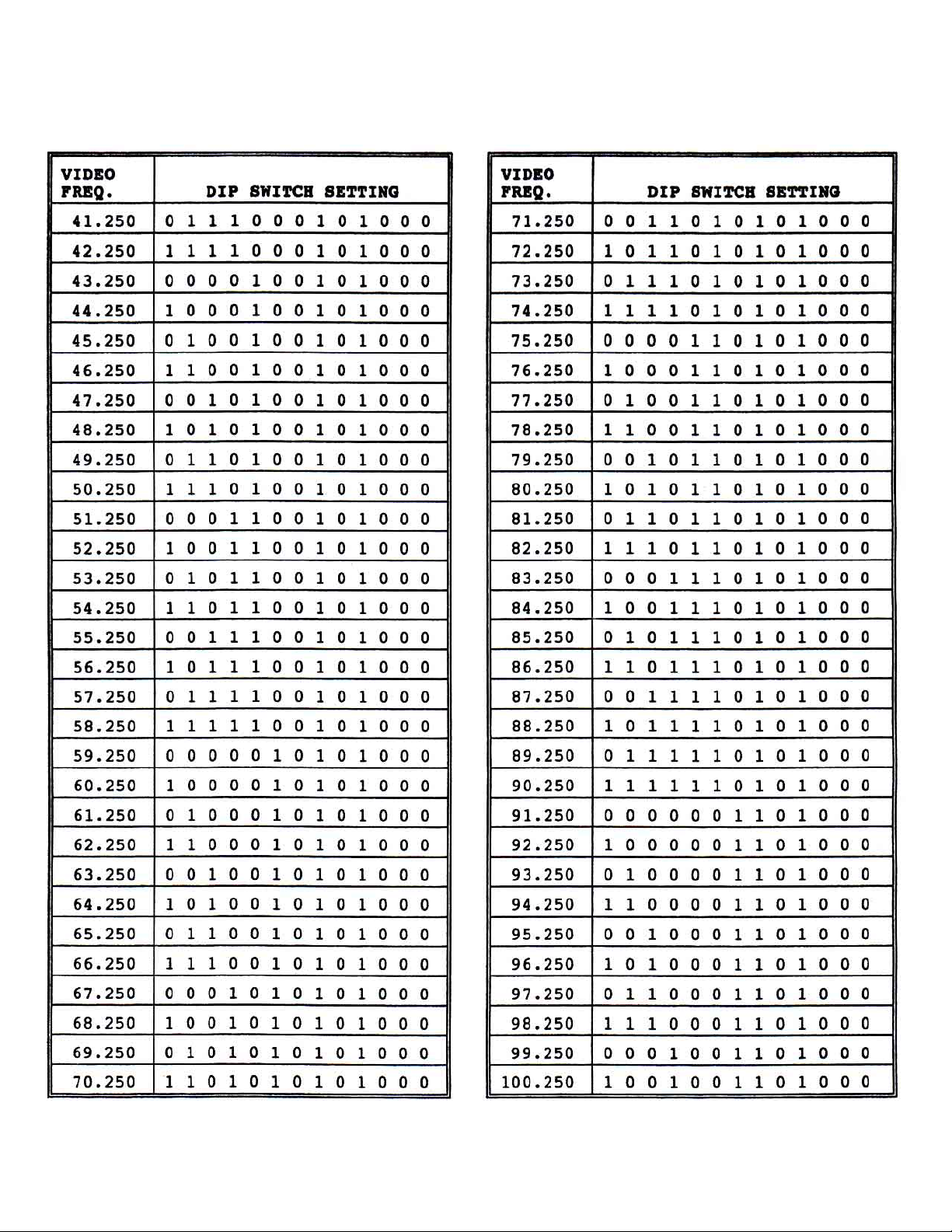
T able 1 - OTM-3000-HR SWITCH SETTINGS
0 = SWITCH DOWN 1 = SWITCH UP
025-000258 REV B
Page 7
Page 8
025-000258 REV B
Page 8
Page 9
025-000258 REV B
Page 9
Page 10
025-000258 REV B
Page 10
Page 11
025-000258 REV B
Page 11
Page 12
025-000258 REV B
Page 12
Page 13
025-000258 REV B
Page 13
 Loading...